steering ISUZU TROOPER 1995 User Guide
[x] Cancel search | Manufacturer: ISUZU, Model Year: 1995, Model line: TROOPER, Model: ISUZU TROOPER 1995Pages: 1928
Page 121 of 1928
DIAGNOSIS 3 -1
STEERING, SUSPENSION
WHEELS AND TIRES
CONTENTS
Diagnosis.............................. . . . . . . . . . . . . . . . . . . . . . . . . . . . . . . . . . . . . . . . . . . . . . . . . . . . . . . . . . . . . . . . . Section 3
Front End
Alignment . . . . . . . . . . . . . . . . . . . . . . . . . . . . . . . . . . . . . . . . . . . . . . . . . . . . . . . . . . . . . . . . . . . . . . . . . . . . . . Section 3A
Power Steering Gear and Pump ................................................................ Section 381
Steering Linkage
........................................................................\
.......... Section 383
Front Suspension . . . . . . . . . . . . . . . . . . . . . . . . . . . . . . . . . . . . . . . . . . . . . . . . . . . . . . . . . . . . . . . . . . . . . . . . . . . . . . . . . . Section
3C
Rear Suspension . . . . . . . . . . . . . . . . . . . . . . . . . . . . . . . . . . . . . . . . . . . . . . . . . . . . . . . . . . . . . . . . . . . . . . . . . . . . . . . . . . . Section 3D
Wheels and
lires . . . . . . . . . . . . . . . . . . . . . . . . . . . . . . . . . . . . . . . . . . . . . . . . . . . . . . . . . . . . . . . . . . . . . . . . . . . . . . . . . . . Section 3E
Supplemental Restraint System Steering Wheel and Column............................. Section 3F4
SECTION 3
DIAGNOSIS
CONTENTS
General Description ................................. 3-1 Power Steering Pump Diagnosis. . . . . . . . . . . . . . . . . . 3-6
General Diagnosis . . . . . . . . . . . . . . . . . . . . . . . . . . . . . . . . . . . 3-2
Steering Column Diagnosis ........................ 3-7
"-"' Power Steering Tire Diagnosis . . . . . . . . . . . . . . . . . . . . . . . . . . . . . . . . . . . . . . . 3-9
System Diagnosis .. .. . . . . . .. . . . .. .. . . . .. .. . . . . . . . 3-5
GENERAL DESCRIPTION
Since the problems in steering, suspension, wheels
and tires
involve several systems, they must all be
considered
when diagnosing a complaint. To identify
the symptom, always road test the vehicle first.
Proceed
with the following preliminary inspections
and correct
any defects which are found.
1. lnspecttires for proper pressure and uneven wear.
2. Raise vehicle on a hoist and inspect front and
rear suspension and steering
linkage for loose or
damaged parts.
3. Spin front wheels. Inspect for out-of-round tires,
out-of-balance tires,
loose and/or rough wheel
bearings.
Page 122 of 1928
3-2 DIAGNOSIS
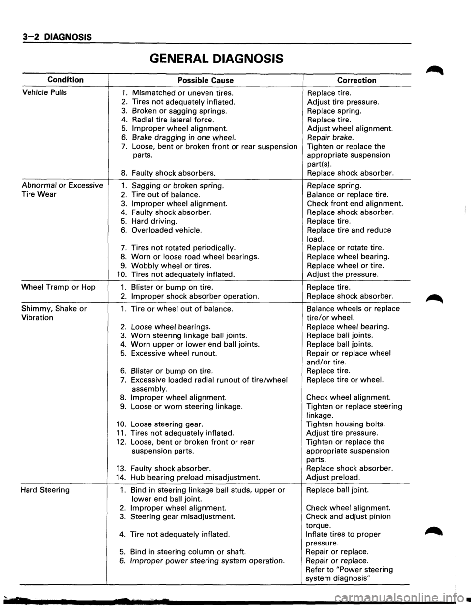
GENERAL DIAGNOSIS
Condition Possible Cause Correction
Vehicle
Pulls 1. Mismatched or uneven tires. Replace tire.
2. Tires not adequately inflated. Adjust tire pressure.
3. Broken or sagging springs. Replace spring.
4. Radial tire lateral force. Replace tire.
5. Improper wheel alignment. Adjust wheel alignment.
6. Brake dragging in one wheel. Repair brake.
7. Loose, bent or broken front or rear suspension Tighten or replace the
parts. appropriate suspension
part(s).
8. Faulty shock absorbers. Replace shock absorber.
Abnormal or Excessive 1. Sagging or broken spring. Replace spring.
Tire Wear
2. Tire out of balance. Balance or replace tire.
3. Improper wheel alignment. Check front end alignment.
4. Faulty shock absorber. Replace shock absorber.
5. Hard driving. Replace tire.
6. Overloaded vehicle. Replace tire
and reduce
load.
7. Tires not rotated periodically. Replace or rotate
tire.
8. Worn or loose road wheel bearings. Replace wheel bearing.
9. Wobbly wheel or tires. Replace wheel or tire.
10. Tires not adequately inflated. Adjust the pressure.
Wheel Tramp or Hop 1. Blister or bump on tire. Replace tire.
2. Improper shock absorber operation. Replace shock absorber.
Shimmy,
Shake or 1. Tire or wheel out of balance. Balance
wheels or replace
Vibration tire/or wheel.
2. Loose wheel bearings. Replace wheel bearing.
3. Worn steering linkage ball joints. Replace ball joints.
4. Worn upper or lower end ball joints. Replace ball joints.
5. Excessive wheel runout. Repair or replace
wheel
and/or tire.
6. Blister or bump on tire. Replace tire.
7. Excessive loaded radial runout of tire/wheel Replace tire or wheel.
assembly.
8. Improper wheel alignment. Check
wheel alignment.
9. Loose or worn steering linkage. Tighten or replace steering
linkage.
10. Loose steering gear. Tighten
housing bolts.
11. Tires not adequately inflated. Adjust tire pressure.
12. Loose, bent or broken front or rear Tighten or replace the
suspension parts. appropriate suspension
parts.
13. Faulty shock absorber. Replace shock absorber.
14. Hub bearing preload misadjustment. Adjust preload.
Hard Steering 1. Bind in steering linkage ball studs, upper or Replace ball joint.
lower end ball joint.
2. Improper wheel alignment. Check wheel alignment.
3. Steering gear misadjustment. Check and adjust pinion
torque.
4. Tire not adequately inflated. Inflate tires to proper
pressure.
5. Bind in steering column or shaft. Repair or replace.
6. Improper power steering
system operation. Repair or replace.
Refer to "Power steering
system diagnosis"
'· •
Page 123 of 1928
DIAGNOSIS 3-3
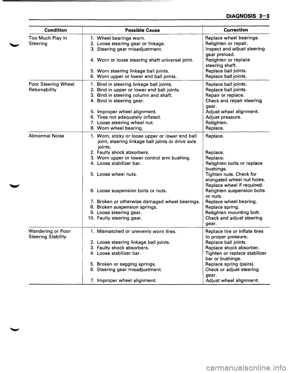
Condition Possible Cause Correction
Too
Much Play In 1. Wheel bearings worn. Replace wheel bearings.
Steering
2. Loose steering gear or linkage. Retighten or repair.
3. Steering
gear misadjustment. Inspect and adjust steering
gear preload.
4. Worn or loose steering shaft universal joint. Retighten or replace
steering shaft.
5. Worn steering linkage ball joints. Replace ball joints.
6. Worn upper or lower end ball joints. Replace ball joints.
Poor Steering
Wheel 1. Bind in steering linkage ball joints. Replace ball joints.
Returnability 2. Bind
in upper or lower end ball joints. Replace ball joints.
3. Bind
in steering column and shaft. Repair
or replace.
4. Bind in steering gear. Check and repair steering
gear.
5. Improper wheel alignment. Adjust wheel alignment.
6. Tires not adequately
inflated. Adjust
pressure.
7. Loose steering wheel nut. Retighten.
8. Worn wheel bearing.
Replace.
Abnormal Noise
1. Worn, sticky or loose upper or lower end ball Replace.
joint, steering linkage
ball joints or drive axle
joints.
2. Faulty shock absorbers.
Replace.
3. Worn upper or lower control arm bushing.
Replace.
4. Loose stabilizer bar. Retighten bolts or replace
bushings.
5. Loose wheel nuts. Tighten nuts. Check for
elongated wheel nut holes.
Replace
wheel if required.
6. Loose suspension bolts or nuts. Retighten suspension bolts
or nuts.
7. Broken or otherwise damaged wheel bearings. Replace wheel bearing.
8. Broken suspension springs. Replace spring.
9. Loose steering gear. Retighten mounting bolt.
10. Faulty steering gear. Check and adjust steering
gear.
Wandering
or Poor 1. Mismatched or unevenly worn tires. Replace tire or inflate tires
Steering
Stability to proper pressure.
2. Loose steering linkage ball joints. Replace ball joints.
3. Faulty shock absorbers. Replace shock absorber.
4. Loose stabilizer bar. Tighten or replace stabilizer
bar or bushings.
5. Broken or sagging springs. Replace spring (pairs).
6. Steering gear misadjustment. Check or adjust steering
gear.
7. Improper wheel alignment.
Adjust wheel alignment.
Page 124 of 1928
3-4 DIAGNOSIS
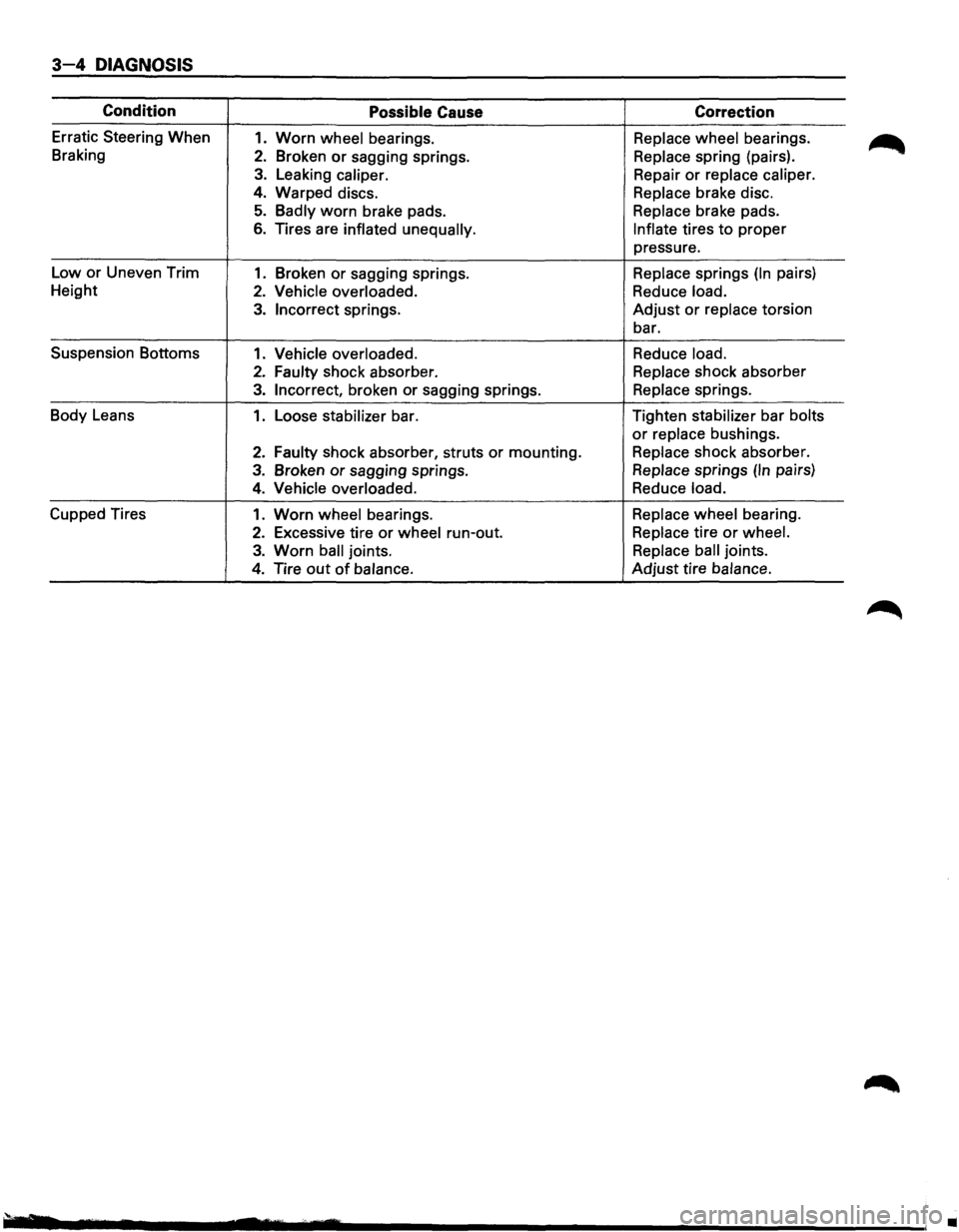
Condition Possible Cause Correction
Erratic Steering When 1. Worn wheel bearings. Replace wheel bearings.
Braking
2. Broken or sagging springs. Replace spring (pairs).
3. Leaking caliper. Repair or replace caliper.
4. Warped discs. Replace brake disc.
5. Badly worn brake pads. Replace brake pads.
6. Tires are inflated unequally. Inflate tires to proper
pressure.
Low or Uneven Trim
1. Broken or sagging springs. Replace springs (In pairs)
Height
2. Vehicle overloaded. Reduce load.
3. Incorrect springs. Adjust or replace torsion
bar.
Suspension Bottoms
1. Vehicle overloaded. Reduce load.
2. Faulty shock absorber. Replace shock absorber
3. Incorrect, broken or sagging springs. Replace springs.
Body Leans
1. Loose stabilizer bar. Tighten stabilizer bar bolts
or replace bushings.
2. Faulty shock
absorber, struts or mounting. Replace shock absorber.
3. Broken or sagging springs. Replace springs (In pairs)
4. Vehicle overloaded. Reduce load.
Cupped Tires 1. Worn wheel bearings. Replace wheel bearing.
2. Excessive tire or wheel run-out. Replace tire or wheel.
3. Worn ball joints. Replace ball joints.
4. Tire out of balance. Adjust tire balance.
•
Page 125 of 1928
DIAGNOSIS 3-5
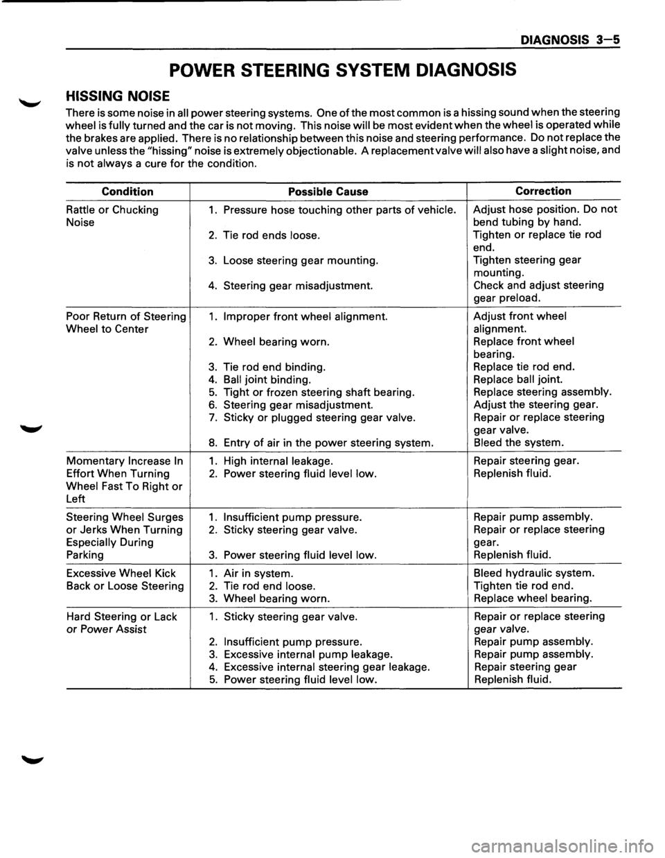
POWER STEERING SYSTEM DIAGNOSIS
HISSING NOISE
There is some noise in all power steering systems. One of the most common is a hissing sound when the steering
wheel is fully turned and the car is not moving. This noise will be most evident when the wheel is operated while
the brakes are applied. There is no relationship between this noise and steering performance. Do not replace the
valve unless the "hissing" noise is extremely objectionable. A replacement valve will also have a slight noise, and
is
not always a cure for the condition.
Condition
Possible Cause Correction
Rattle or Chucking 1. Pressure
hose touching other parts of vehicle. Adjust hose position. Do not
Noise bend
tubing by hand.
2. Tie rod ends loose. Tighten or replace tie rod
end.
3. Loose steering gear mounting. Tighten
steering gear
mounting.
4. Steering gear misadjustment. Check and adjust steering
gear
preload.
Poor Return of Steering 1. Improper front wheel alignment. Adjust front wheel
Wheel
to Center alignment.
2. Wheel bearing worn. Replace front wheel
bearing.
3. Tie rod end binding. Replace tie rod end.
4. Ball joint binding. Replace ball joint.
5. Tight or frozen steering shaft bearing. Replace steering assembly.
6. Steering gear misadjustment. Adjust the steering gear.
7. Sticky or plugged steering gear valve. Repair or replace steering
gear
valve.
8. Entry of air in the power steering system. Bleed the system.
Momentary Increase In 1. High internal leakage. Repair steering gear.
Effort When Turning
2. Power steering fluid level low. Replenish
fluid.
Wheel
Fast To Right or
Left
Steering
Wheel Surges 1. Insufficient pump pressure. Repair pump assembly.
or Jerks
When Turning 2. Sticky steering gear valve. Repair or replace steering
Especially During gear.
Parking
3. Power steering fluid level low. Replenish
fluid.
Excessive Wheel Kick 1. Air in system. Bleed hydraulic system.
Back
or Loose Steering 2. Tie rod end loose. Tighten tie rod end.
3. Wheel bearing worn. Replace wheel bearing.
Hard Steering
or Lack 1. Sticky steering gear valve. Repair or replace steering
or Power Assist gear valve.
2. Insufficient pump pressure.
Repair pump assembly.
3. Excessive internal pump leakage. Repair
pump assembly.
4. Excessive internal steering gear leakage. Repair steering gear
5. Power steering fluid level low. Replenish
fluid.
Page 126 of 1928
3-6 DIAGNOSIS
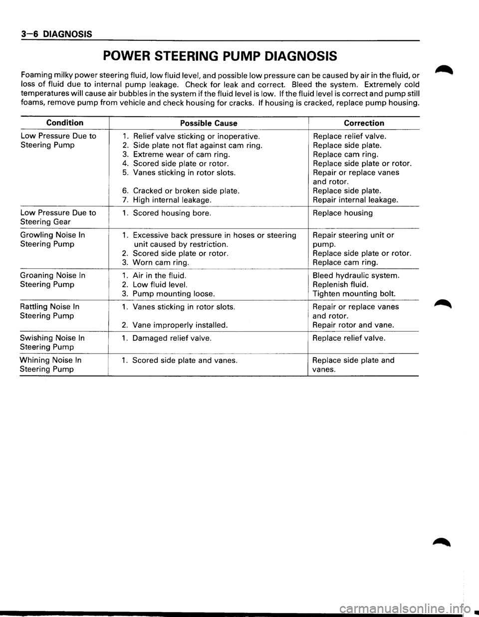
POWER STEERING PUMP DIAGNOSIS
Foaming milky power steering fluid, low fluid level, and possible low pressure can be caused by air in the fluid, or
loss of fluid due to internal pump leakage. Check for leak and correct. Bleed the system. Extremely cold
temperatures
will cause air bubbles in the system if the fluid level is low. If the fluid level is correct and pump still
foams, remove pump from vehicle and check housing for cracks. If housing is cracked, replace pump housing.
Condition
Possible Cause Correction
Low Pressure
Due to 1. Relief valve sticking or inoperative. Replace relief valve.
Steering Pump
2. Side plate not flat against cam ring. Replace side plate.
3. Extreme wear of cam ring. Replace cam ring.
4. Scored side plate or rotor. Replace
side plate or rotor.
5. Vanes sticking in rotor slots. Repair or replace vanes
and rotor.
6. Cracked or broken side plate. Replace side plate.
7. High internal leakage. Repair internal leakage.
Low Pressure Due to 1. Scored housing bore. Replace housing
Steering Gear
Growling Noise
In 1. Excessive back pressure in hoses or steering Repair
steering unit or
Steering Pump
unit caused by restriction. pump.
2. Scored side plate or rotor. Replace
side plate or rotor.
3. Worn cam ring. Replace
cam ring.
Groaning Noise
In 1. Air in the fluid. Bleed hydraulic system.
Steering Pump
2. Low fluid level. Replenish fluid.
3. Pump mounting loose. Tighten
mounting bolt.
Rattling Noise
In 1. Vanes sticking in rotor slots. Repair or replace
vanes
Steering Pump and rotor.
2. Vane improperly installed. Repair rotor and vane.
Swishing Noise
In 1. Damaged relief valve. Replace
relief valve.
Steering Pump
Whining Noise
In 1. Scored side plate and vanes. Replace
side plate and
Steering Pump
vanes.
•
Page 127 of 1928
LOCK SYSTEM
Condition
Will Not Unlock
Will Not Lock
Key
Cannot be
Removed in "OFF-
LOCK"
COLUMN
Condition
Noise in Column
DIAGNOSIS 3-7
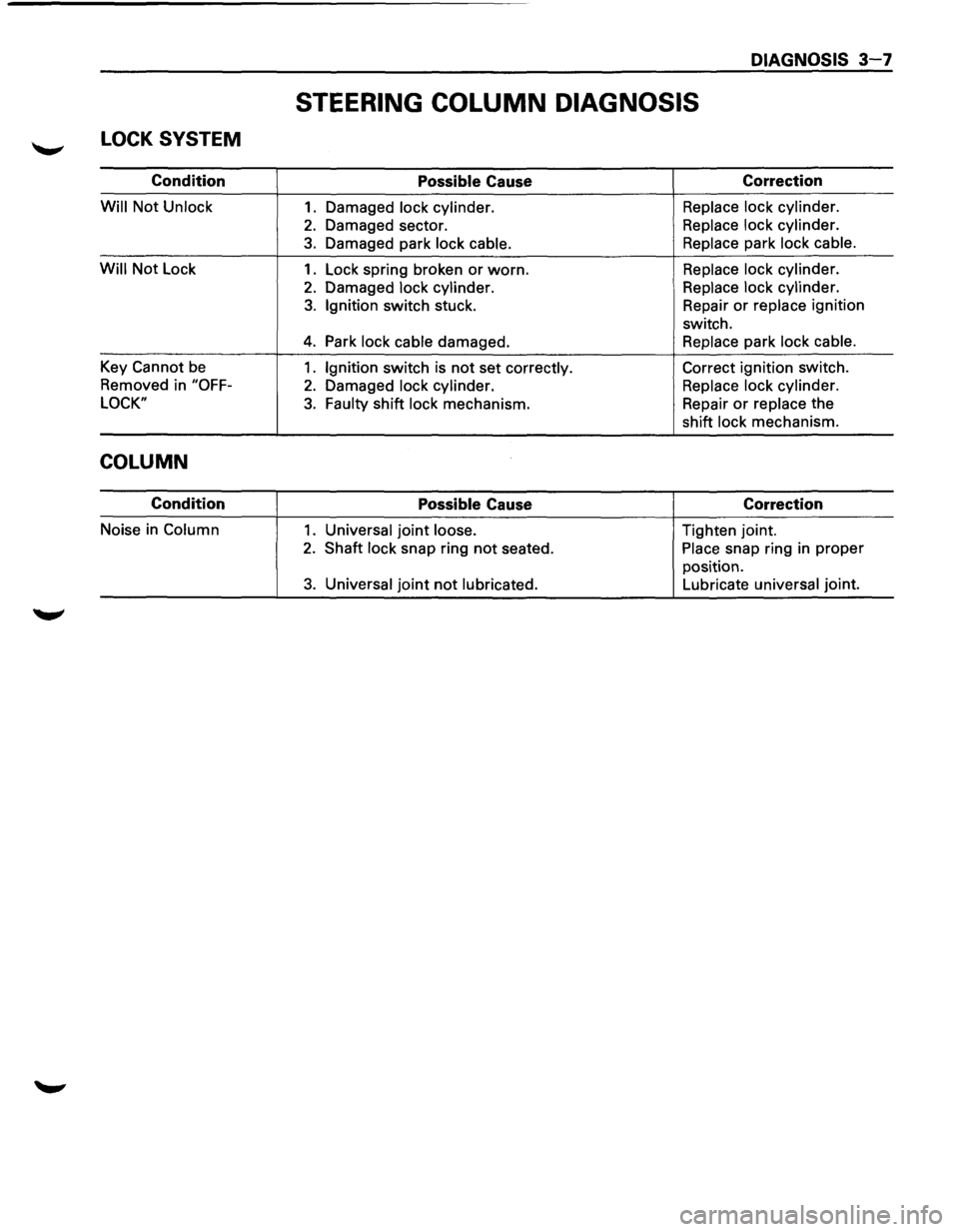
STEERING COLUMN DIAGNOSIS
Possible Cause
1. Damaged lock cylinder.
2. Damaged sector.
3. Damaged park lock cable.
1. Lock spring broken or worn.
2. Damaged lock cylinder.
3. Ignition switch stuck.
4. Park lock cable damaged.
1. Ignition switch is not set correctly.
2. Damaged lock cylinder.
3. Faulty shift lock mechanism.
Possible Cause
1. Universal joint loose.
2. Shaft lock snap ring not seated.
3. Universal joint not lubricated.
Correction
Replace lock cylinder.
Replace lock cylinder.
Replace park lock cable.
Replace lock cylinder.
Replace lock cylinder.
Repair
or replace ignition
switch.
Replace park lock cable.
Correct ignition switch.
Replace lock cylinder.
Repair
or replace the
shift lock mechanism.
Correction
Tighten joint.
Place snap ring in proper
position.
Lubricate universal joint.
Page 130 of 1928
3-10 DIAGNOSIS
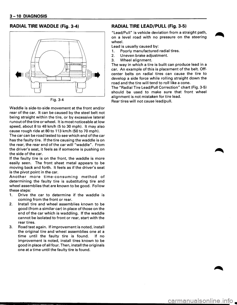
RADIAL TIRE WADDLE (Fig. 3-4)
Fig. 3-4
Waddle is side-to-side
movement at the front and/or
rear of the car. It can be caused by the steel belt not
being straight within the tire, or by excessive lateral
runout of the tire or wheel. It is most noticeable at low
speed, about 8 to 48 km/h (5 to 30 mph). It may also
cause
rough ride at 80 to 113 km/h (50 to 70 mph).
The car can be road tested
to see which end of the car
has
the faulty tire. If the tire causing the waddle is on
the rear, the rear end
of the car will "waddle". From
the
driver's seat, it feels as if someone is pushing on
the side
of the car.
If the faulty tire is on the front, the waddle is more
easily seen. The front sheet metal appears to be
moving back and forth. It feels as if the driver's seat
is
the pivot point in the car.
Another more time-consuming method of
determining the faulty tire is substituting tire and
wheel assemblies
that are known to be good. Follow
these steps:
1. Drive the car to determine if the waddle is
coming from the front or rear.
2. Install tire and wheel assemblies known to be
good (from a similar car) in place ofthose on the
end
of the car which is waddling. If the waddle
cannot be isolated to front or rear, start with the
rear tires.
3. Road test again. If improvement is noted, install
the original tire and wheel assemblies one at a
time until the faulty tire is found. If no
improvement is noted, install tires known to be
good in place of all four. Then, install the originals
one at a
time until the faulty tire is found.
RADIAL TIRE LEAD/PULL (Fig. 3-5)
"Lead/Pull" is vehicle deviation from a straight path,
on a level road
with no pressure on the steering
wheel.
Lead is usually caused by:
1. Poorly manufactured radial tires.
2. Uneven brake adjustment.
3. Wheel alignment.
The
way in which a tire is built can produce lead in a
car.
An example of this is placement of the belt. Off
center belts on radial tires can cause the tire to
develop a side force while rolling straight down the
road and the tire will tend to roll like a cone.
The
"Radial Tire Lead/Pull Correction" chart (Fig. 3-5)
should be used to make sure that front wheel
alignment is not mistaken for tire lead.
Rear
tires will not cause lead/pull.
II
Page 133 of 1928
FRONT END ALIGNMENT 3A-1
SECTION3A
FRONT END ALIGNMENT
CAUTION:
When fasteners are removed, always reinstall them at the same location from which they were removed. If
a fastener needs to be replaced, use the correct part number fastener for that application. If the correct part
number fastener is not available, a fastener of equal size and strength (or stronger) may be used. Fasteners
that are not reused, and those requiring thread locking compound will be called out. The correcttorque value
must be used when installing fasteners that require it. If the above conditions are not followed, parts or
system damage could result.
CONTENTS
General Description ................................ 3A-1
Camber Adjustment ............................. 3A-4
Definition of Terms .............................. 3A·2 Toe-in Adjustment ............................... 3A-5
On-Vehicle Service ................................. 3A-3 Maximum Steering Angle Adjustment ....... 3A-5
Inspection ......................................... 3A-3 Main Data and Specifications ..................... 3A-6
Trim Height Adjustment ........................ 3A-3 General Specifications .......................... 3A-6
Caster
Adjustment ............................... 3A-3 Torque Specifications ........................... 3A-6
GENERAL DESCRIPTION
"Front End Alignment" refers to the angular
relationship between the front wheels, the front
suspension attaching parts and the ground.
Proper front end alignment must be maintained in
order to insure efficient steering, good directional
stability and to prevent abnormal tire wear.
The
most important factors of front end alignment are
wheel toe-in, wheel camber and axle caster.
Page 134 of 1928
3A-2 FRONT END ALIGNMENT
DEFINITION OF TERMS
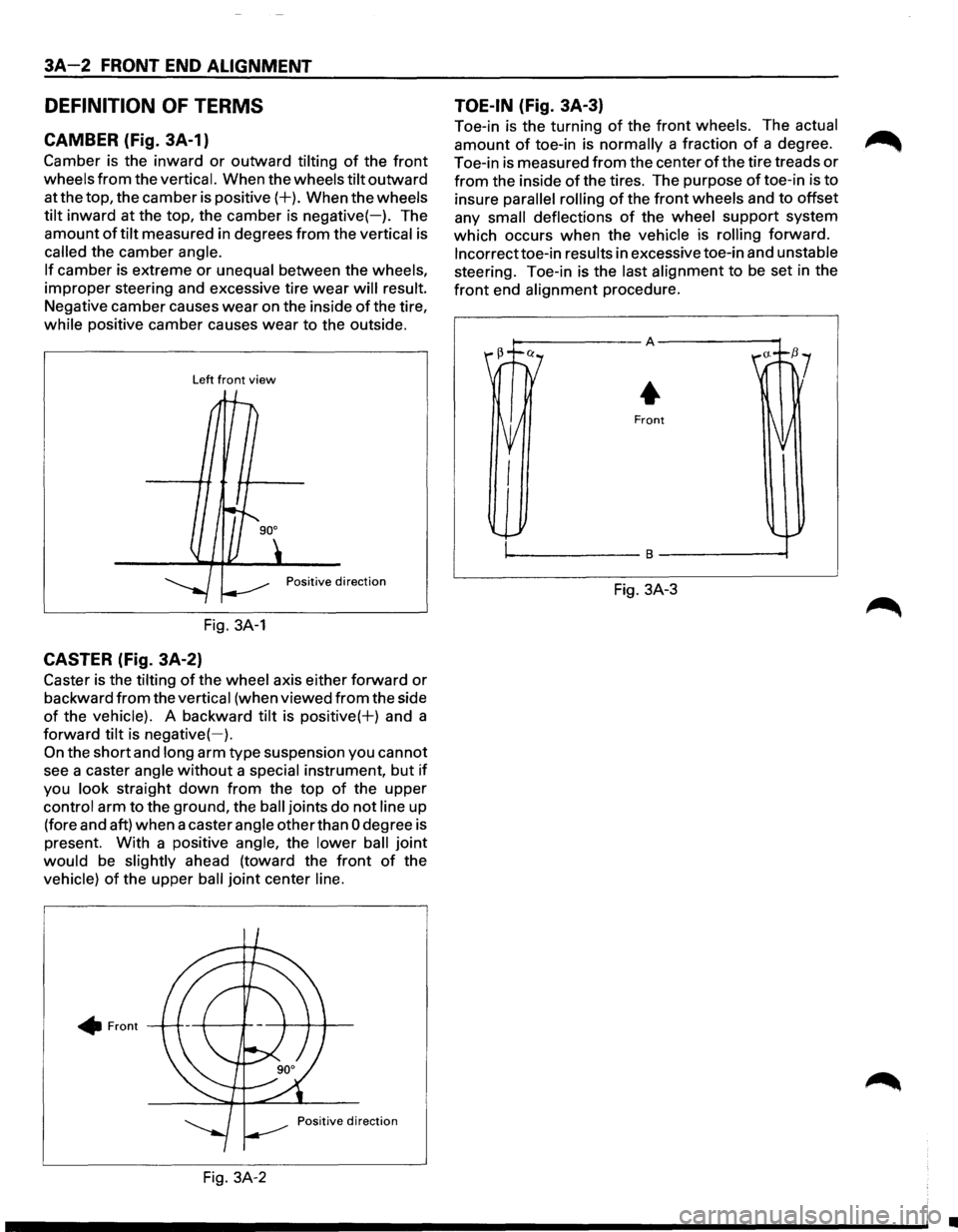
CAMBER (Fig. 3A-1)
Camber is the inward or outward tilting of the front
wheels from the vertical. When the wheels tilt outward
at the top, the camber is
positive(+). When the wheels
tilt inward at the top, the camber is negative(-). The
amount
of tilt measured in degrees from the vertical is
called the camber angle.
If camber is extreme or unequal between the wheels,
improper steering and excessive tire
wear will result.
Negative camber causes
wear on the inside of the tire,
while positive camber causes wear to the outside.
Left front view
Positive direction
Fig. 3A-1
CASTER (Fig. 3A-2)
Caster is the tilting of the wheel axis either forward or
backward from the vertical (when viewed from the side
of the vehicle). A backward tilt is positive(+) and a
forward tilt is
negative(-).
On the short and long arm type suspension you cannot
see a caster angle
without a special instrument, but if
you look straight down from the top of the upper
control arm to the ground, the
ball joints do not line up
(fore and aft) when a caster angle other than
0 degree is
present. With a positive angle, the lower
ball joint
would be slightly ahead (toward the front of the
vehicle)
of the upper ball joint center line .
• Front
Fig. 3A-2
TOE-IN (Fig. 3A-3)
Toe-in is the turning of the front wheels. The actual
amount of toe-in is normally a fraction of a degree.
Toe-in is measured
from the center of the tire treads or
from the inside of the tires. The purpose of toe-in is to
insure
parallel rolling of the front wheels and to offset
any
small deflections of the wheel support system
which occurs
when the vehicle is rolling forward.
lncorrecttoe-in results in excessive toe-in and unstable
steering. Toe-in is the last alignment to
be set in the
front end alignment procedure.
Fig. 3A-3
•