steering ISUZU TROOPER 1995 Owner's Guide
[x] Cancel search | Manufacturer: ISUZU, Model Year: 1995, Model line: TROOPER, Model: ISUZU TROOPER 1995Pages: 1928
Page 146 of 1928
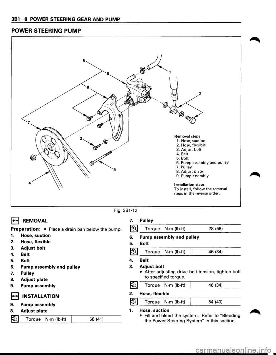
381-8 POWER STEERING GEAR AND PUMP
POWER STEERING PUMP
<
4
Removal steps
1. Hose, suction
2. Hose,
flexible 3. Adjust bolt 4. Belt 5. Bolt 6. Pump assembly and pulley
7. Pulley
8. Adjust
plate
9. Pump assembly
Installation
steps To install, follow the removal steps in the reverse order.
Fig. 381-12
B REMOVAL
Preparation: • Place a drain pan below the pump.
1. Hose, suction
2. Hose, flexible
3. Adjust bolt
4. Belt
5.
6.
7.
8.
9.
Bolt
Pump assembly and pulley
Pulley
Adjust plate
Pump assembly
1•+1 INSTALLATION
9. Pump assembly
8. Adjust plate
~~~ Torque N·m (lb·ft) 56 (41)
7. Pulley
~~~ Torque N·m (lb·ft)
6. Pump assembly and pulley
5. Bolt
~~~ Torque N·m (lb·ft)
4.
3.
Belt
Adjust bolt
78 (58)
46 (34)
• After adjusting drive belt tension, tighten bolt
to specified torque.
I~I_T_o_rq....:...u_e_N_·_m_(_lb_·ft_)____! ___ 4_6...:..(3_4...:_) __ _
2. Hose, flexible
~~~ Torque N·m (lb·ft) 54 (40)
1. Hose, suction
• Fill and bleed the system. Refer to "Bleeding
the Power Steering System" in this section.
Page 147 of 1928
POWER STEERING GEAR AND PUMP 381-9
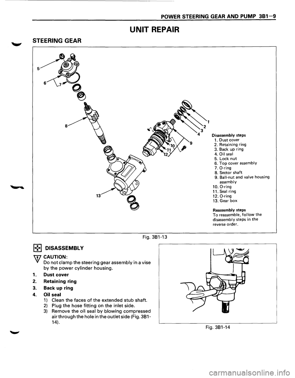
STEERING GEAR
1.,!,.1 DISASSEMBL V
W CAUTION:
UNIT REPAIR
Fig. 381-13
Yf Do not clamp the steering gear assembly in a vise
by the power cylinder housing.
1. Dust cover
2. Retaining ring
3. Back up ring
4. Oil seal
1) Clean the faces of the extended stub shaft.
2) Plug the hose fitting on the inlet side.
3) Remove the oil seal by blowing compressed
air through the
hole in the outlet side (Fig. 381-
14).
Disassembly steps
1. Dust cover
2. Retaining ring
3. Back up ring
4.
Oil seal 5. Lock nut 6. Top cover assembly
7. 0-ring
8. Sector shaft
9.
Ball-nut and valve housing
assembly
10. 0-ring
11. Seal ring
12. 0-ring
13. Gear
box
Reassembly steps
To reassemble, follow the
disassembly steps in the
reverse order.
Fig. 381-14
Page 148 of 1928
381-10 POWER STEERING GEAR AND PUMP
5. Lock nut
• Remove the adjusting screw lock nut and turn
the adjusting
screw counter-clockwise to
remove the preload between the sector gear
and the rack piston, then remove the
top cover
bolts.
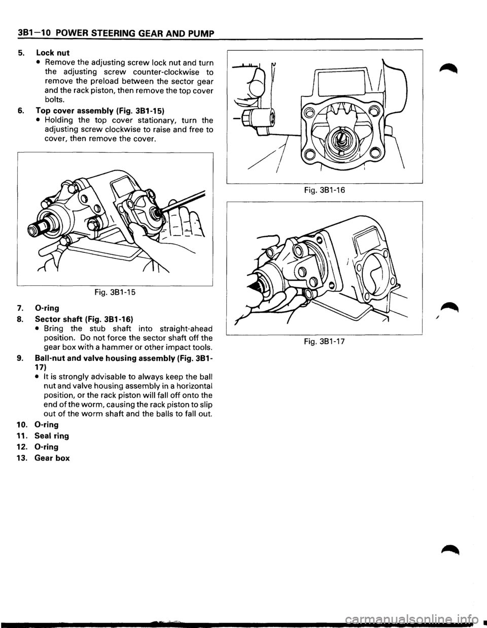
6. Top cover assembly (Fig. 381-15)
• Holding the top cover stationary, turn the
adjusting screw
clockwise to raise and free to
cover, then remove the cover.
Fig. 381-15
7. 0-ring
8. Sector shaft (Fig. 381-16)
• Bring the stub shaft into straight-ahead
position. Do not force the sector shaft
off the
gear
box with a hammer or other impact tools.
9. Ball-nut and valve housing assembly (Fig. 381-
17)
• It is strongly advisable to always keep the ball
nut and valve housing assembly in a horizontal
position, or the rack piston will fall off onto the
end
of the worm, causing the rack piston to slip
out of the worm shaft and the balls to fall out.
10. 0-ring
11. Seal ring
12.
0-ring
13. Gear box
Fig. 381-16
Fig. 381-17
•
Page 149 of 1928
![ISUZU TROOPER 1995 Owners Guide (1!] INSPECTION AND REPAIR
Inspect the following parts for wear, damage or any
other abnormal conditions.
• Bearing
• Ball-nut and valve housing
• Sector shaft
• Top cover
• Gear](/img/61/57183/w960_57183-148.png "ISUZU TROOPER 1995 Owners Guide (1!] INSPECTION AND REPAIR
Inspect the following parts for wear, damage or any
other abnormal conditions.
• Bearing
• Ball-nut and valve housing
• Sector shaft
• Top cover
• Gear")
(1!] INSPECTION AND REPAIR
Inspect the following parts for wear, damage or any
other abnormal conditions.
• Bearing
• Ball-nut and valve housing
• Sector shaft
• Top cover
• Gear box
• Needle bearing
• Dust seal
• Seal ring
• Gasket
Ball-nut rotation (fig. 381-18)
Hold the ball nut and valve housing assembly vertically
and see
if the ball-nut lowers by turning smoothly. If
the ball-nut does not lower smoothly, check the worm
shaft for bending and foreign matter.
NOTE:
When testing the ball nut and valve housing assembly,
do not let it travel all the way to the end of worm shaft,
or damage to the ball tubes will result.
• Check sector shaft outside diameter (Fig. 381-
19).
~~~ Limit mm (in) 31.7 (1.25)
Fig. 3B1-18
Fig. 3B1-19
POWER STEERING GEAR AND PUMP 381-11
Seal ring setting (fig. 381-20)
8.
~·
Note the setting direction. Always install a
new part.
Apply a thin coat of power steering fluid to lip of
each part.
Dust seal setting (Fig. 381-20)
r=l • Note the setting direction. Always install a
1.=.1 new part.
l<=l()l • Apply a thin coat of power steering fluid to lip of
each part.
Dust seal
Fig. 3B1-20
Gasket setting (fig. 381-21)
1 .. 1• Note the setting direction.
a:;::::;::] • Apply a thin coat of power steering fluid to lip of
D each part.
Fig.
3B1-21
Page 150 of 1928
381 -12 POWER STEERING GEAR AND PUMP
l•!+l REASSEMBLY
13. Gear box
12.
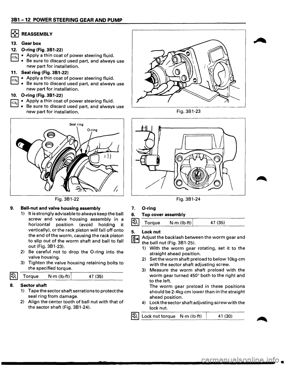
0-ring (fig. 381-22)
r:::;:, • Apply a thin coat of power steering fluid.
D • Be sure to discard used part, and always use
new part for installation.
11. Seal ring (fig. 381-22)
r:::;:, • Apply a thin coat of power steering fluid.
D • Be sure to discard used part, and always use
new part for installation.
10.
0-ring (fig. 381-22)
r:::;:, • Apply a thin coat of power steering fluid.
D • Be sure to discard used part, and always use
new part for installation.
Seal ring
Fig. 3B1-22
9.
Ball-nut and valve housing assembly
1) It is strongly advisable to always keep the ball
screw and valve housing assembly in a
horizontal position (avoid holding it
vertically), or the rack piston will fall off onto
the end of the worm, causing the rack piston
to slip out of the worm shaft and ball to fall
out (Fig. 3B1-23).
2) Be careful not to drop the 0-ring into the
valve housing.
3) Tighten the valve housing retaining bolts to
the specified torque.
~~~ Torque N·m (lb.ft) I 47 (35)
8. Sector shaft
1) Tape the sector shaft serrations to protect the
seal ring from damage.
2) Align the center tooth of ball nut with that of
the sector shaft (Fig. 3B1-24). Fig.
3B1-23
Fig. 3B1-24
7. 0-ring
6. Top cover assembly
~~~ Torque N-m (lb·ftl I 47 (35)
5. Lock nut
r:cJ Adjust the backlash between the worm gear and
L:D the ball nut (Fig. 3B1-25).
1) With the worm gear rotating, set it to the
straight ahead position.
2) Set the worm shaft preload to below 1 Okg-cm
with the sector shaft adjusting screw.
3) Measure the worm shaft preload with the
worm gear turned 450° both to the right and
to the left.
The worm gear preload in these positions
should be 2-4kg-cm lower than in the straight
ahead position.
4) Lock the sector shaft adjusting screw with the
lock nut.
~~~ Lock nut torque N-m (lb·ft) I 41 (30)
•
Page 151 of 1928
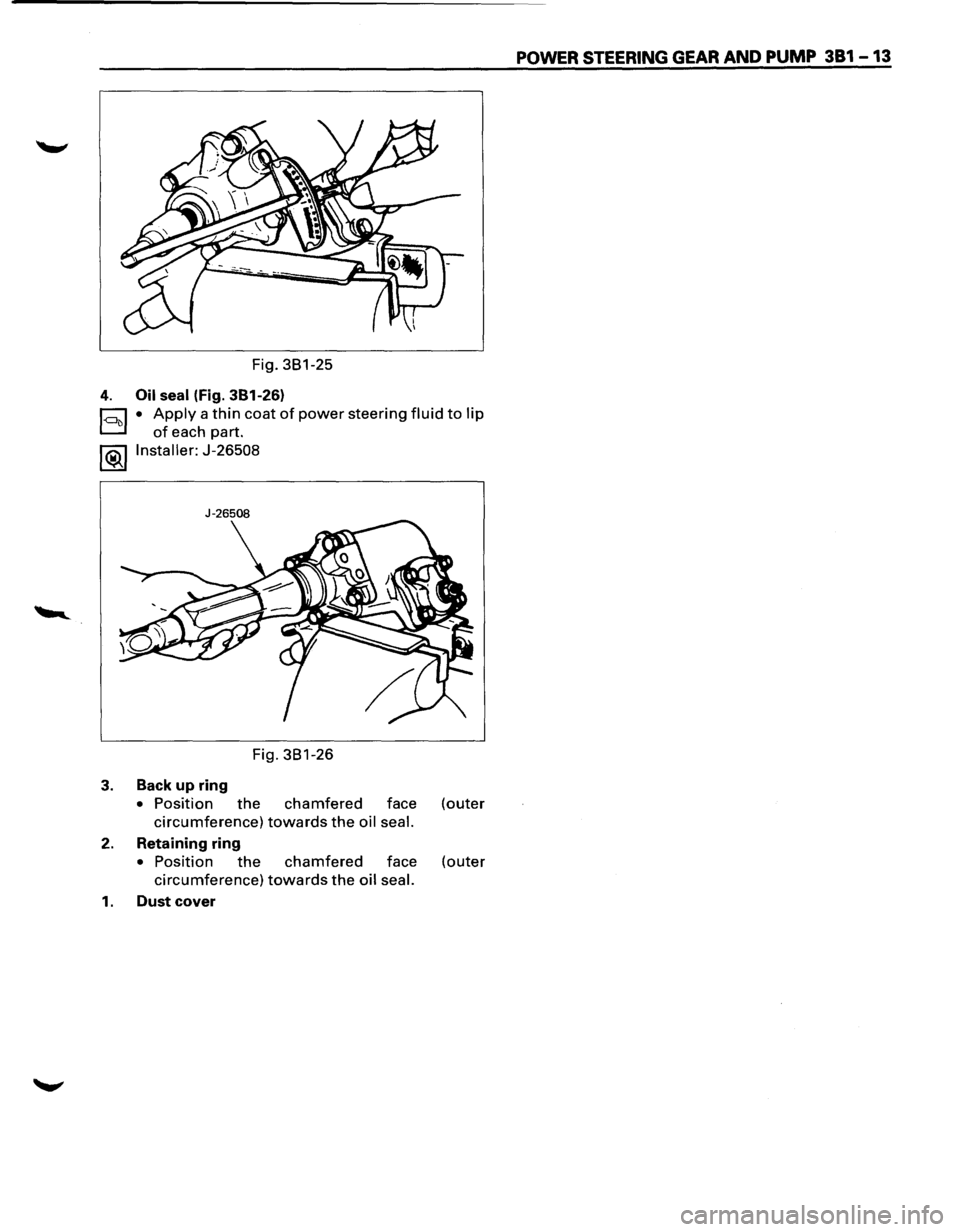
Fig. 381-25
4. Oil seal (Fig. 381-26)
~ • Apply a thin coat of power steering fluid to lip
D of each part.
l®..llnstaller: J-26508
J-26508
Fig. 381-26
3. Back up ring
• Position the chamfered face (outer
circumference) towards the oil seal.
2. Retaining ring
• Position the chamfered face (outer
circumference) towards the oil seal.
1. Dust cover
POWER STEERING GEAR AND PUMP 381 -13
Page 152 of 1928
381-14 POWER STEERING GEAR AND PUMP
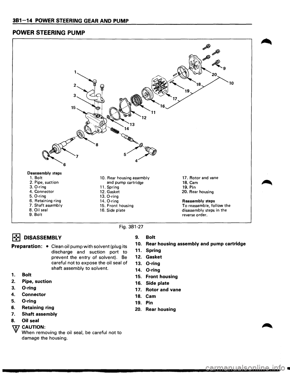
POWER STEERING PUMP
Desassembly steps 1. Bolt 10. Rear housing assembly 2. Pipe, suction
and pump cartridge
3. 0-ring 11. Spring 4. Connector
12. Gasket
5. 0-ring 13. 0-ring 6. Retaining ring
14. 0-ring 7. Shaft assembly 15. Front housing
8. Oil seal 16. Side plate 9. Bolt
Fig. 381-27
l•!•l DISASSEMBLY 9. Bolt
17. Rotor and vane
18.Cam 19. Pin 20. Rear housing
Reassembly steps
10
To reassemble, follow the disassembly steps in the
reverse order.
Preparation: • Clean oil pump with solvent (plug its
discharge and suction
port to
prevent the entry of solvent). Be
careful not to expose the oil seal of
shaft assembly to solvent.
1 0. Rear housing assembly and pump cartridge
1. Bolt
2. Pipe, suction
3. 0-ring
4. Connector
5. 0-ring
6. Retaining ring
7. Shaft assembly
8. Oil seal
'\fl CAUTION:
~ When removing the oil seal, be careful not to
damage the housing.
11. Spring
12. Gasket
13. 0-ring
14. 0-ring
15. Front housing
16. Side
plate
17. Rotor and vane
18.
Cam
19. Pin
20. Rear housing
•
Page 153 of 1928
[1!) INSPECTION AND REPAIR
Make all necessary adjustments, repairs, and part
replacements
if wear, damage, or other problems are
discovered during inspection.
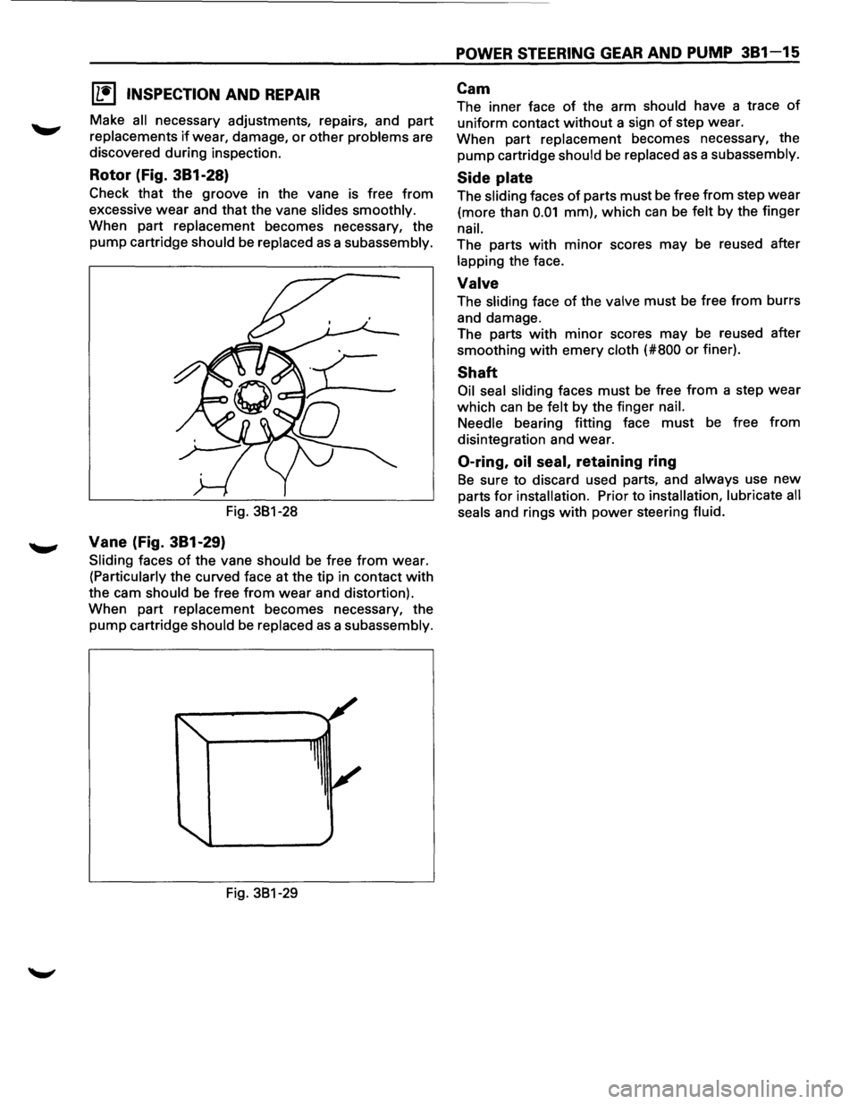
Rotor (Fig. 381-28)
Check that the groove in the vane is free from
excessive wear and that the vane slides smoothly.
When part replacement becomes necessary, the
pump cartridge
should be replaced as a subassembly.
Fig. 381-28
Vane (Fig. 381-29)
Sliding faces of the vane should be free from wear.
(Particularly the curved face at the tip in contact with
the cam should be free from wear and distortion).
When part
replacement becomes necessary, the
pump cartridge should be replaced as a subassembly.
Fig. 381-29
POWER STEERING GEAR AND PUMP 381-15
Cam
The inner face of the arm should have a trace of
uniform contact without a sign of step wear.
When part
replacement becomes necessary, the
pump cartridge should be replaced as a subassembly.
Side plate
The sliding faces of parts must be free from step wear
(more than 0.01 mm), which can be felt by the finger
nail.
The parts with minor scores may be reused after
lapping the face.
Valve
The sliding face of the valve must be free from burrs
and damage.
The parts
with minor scores may be reused after
smoothing
with emery cloth (#800 or finer).
Shaft
Oil seal sliding faces must be free from a step wear
which can be felt by the finger nail.
Needle
bearing fitting face must be free from
disintegration and wear.
0-ring, oil seal, retaining ring
Be sure to discard used parts, and always use new
parts for installation. Prior to installation, lubricate all
seals
and rings with power steering fluid.
Page 154 of 1928
381-16 POWER STEERING GEAR AND PUMP
l•!•l REASSEMBL V
20. Rear housing
19. Pin
18. Cam
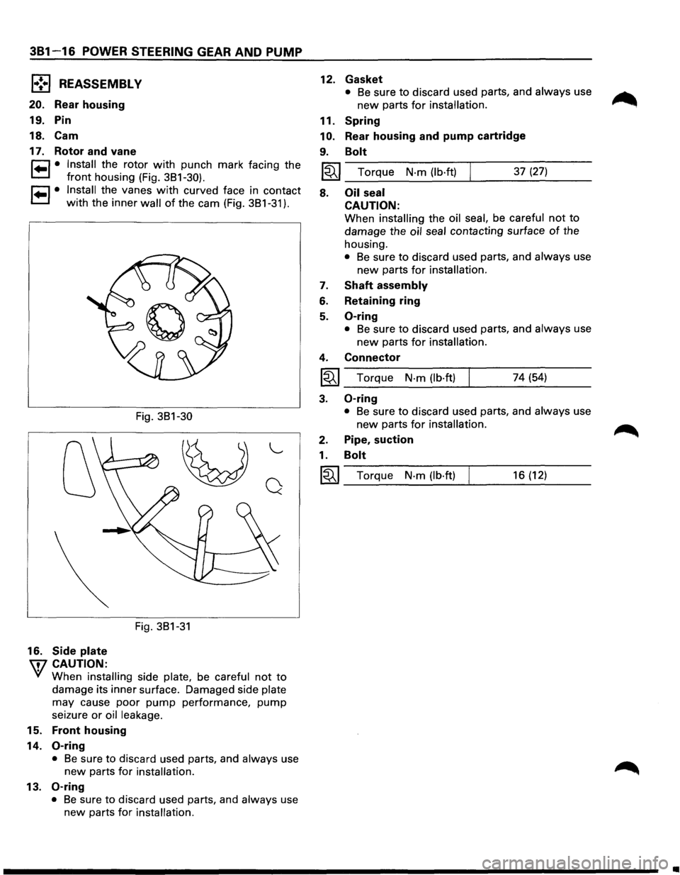
17. Rotor and vane
r=1 • Install the rotor with punch mark facing the
t=1 front housing (Fig. 3B1-30).
r=1 • Install the vanes with curved face in contact
t=1 with the inner wall of the cam (Fig. 3B1-31 ).
16. Side plate
\fl CAUTION:
Fig. 3B1-30
~
Fig. 3B1-31
"---
Q
'if When installing side plate, be careful not to
damage its inner surface. Damaged side plate
may cause poor pump performance, pump
seizure or oil leakage.
15. Front housing
14.
0-ring
• Be sure to discard used parts, and always use
new parts for installation.
13. 0-ring
• Be sure to discard used parts, and always use
new parts
for installation.
12.
11.
10.
9.
Gasket
• Be sure to discard used parts, and always use
new parts for installation.
Spring
Rear housing and pump cartridge
Bolt
l~I_T_o_rq_u_e_N_·_m_(_lb_·f_tl____. ___ 3_7_(2_7_) __ _
8.
7.
6.
5.
4.
~
3.
2.
1.
~
Oil seal
CAUTION:
When installing the oil seal, be careful not to
damage the oil seal contacting surface of the
housing.
• Be sure to discard used parts, and always use
new parts for installation.
Shaft assembly
Retaining ring
0-ring
• Be sure to discard used parts, and always use
new parts for installation.
Connector
Torque N·m (lb·ft) 74 (54)
0-ring
• Be sure to discard used parts, and always use
new parts for installation.
Pipe, suction
Bolt
Torque N·m (lb·ft) 16 (12)
..
Page 155 of 1928
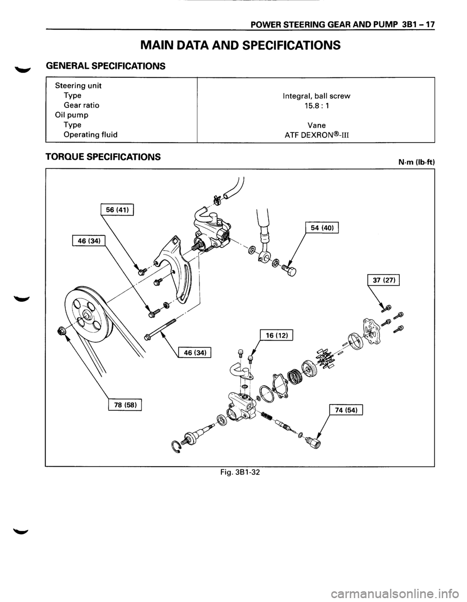
POWER STEERING GEAR AND PUMP 381-17
MAIN DATA AND SPECIFICATIONS
GENERAL SPECIFICATIONS
Steering unit
Type
Gear ratio
Oil pump
Type
Operating
fluid
TORQUE SPECIFICATIONS
Fig. 381-32
Integral, ball screw
15.8: 1
Vane
ATF
DEXRON®-m
N·m (lb.ft)