brake ISUZU TROOPER 1995 Workshop Manual
[x] Cancel search | Manufacturer: ISUZU, Model Year: 1995, Model line: TROOPER, Model: ISUZU TROOPER 1995Pages: 1928
Page 1502 of 1928
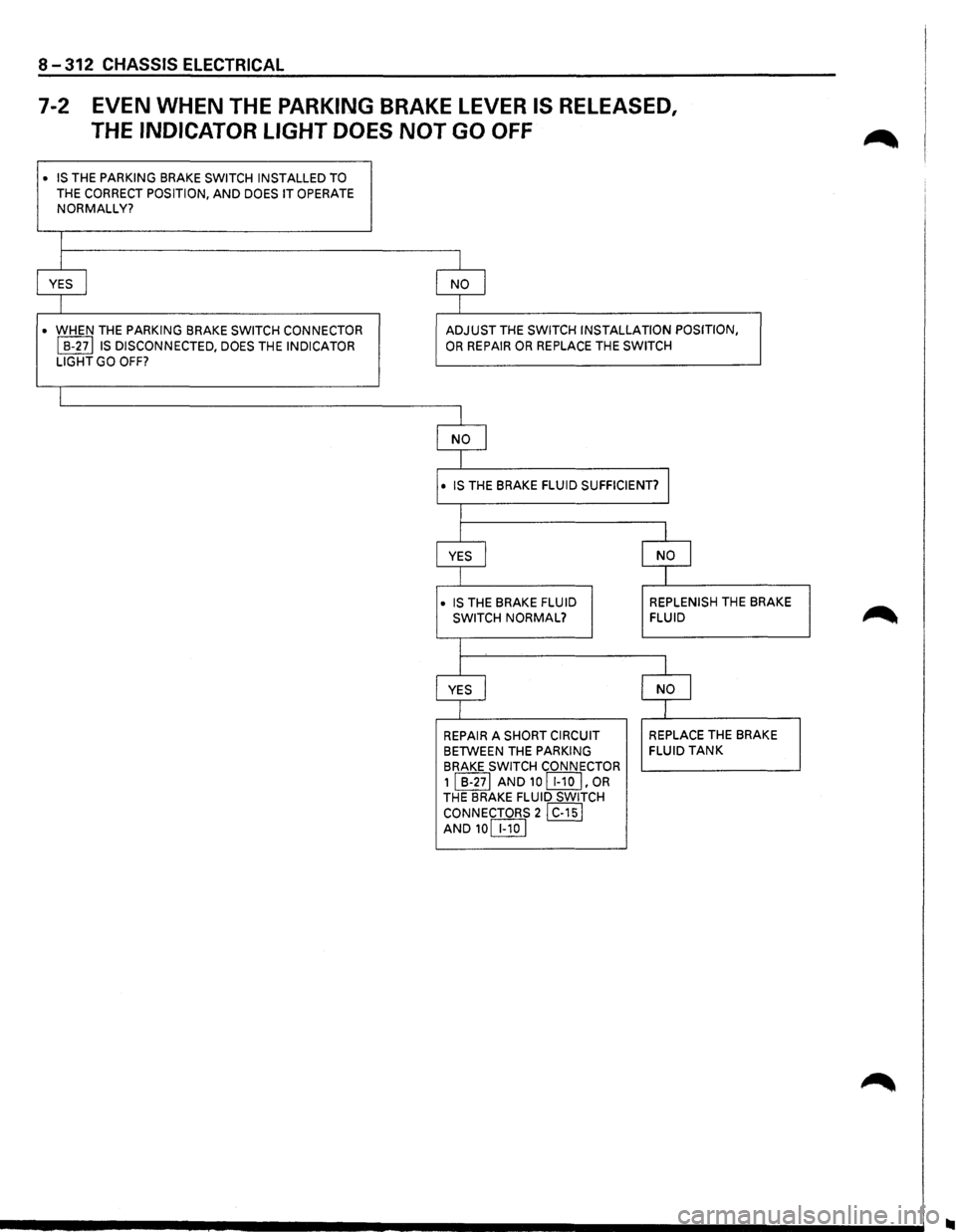
8-312 CHASSIS ELECTRICAL
7-2 EVEN WHEN THE PARKING BRAKE LEVER IS RELEASED,
THE
INDICATOR LIGHT DOES NOT GO OFF
• IS THE PARKING BRAKE SWITCH INSTALLED TO
THE CORRECT POSITION, AND DOES IT OPERATE NORMALLY?
I
I I
YES I NO I
I I
• WHEN THE PARKING BRAKE SWITCH CONNECTOR ADJUST THE SWITCH INSTALLATION POSITION,
I B-27lls DISCONNECTED, DOES THE INDICATOR OR REPAIR OR REPLACE THE SWITCH
LIGHT GO
OFF?
I
I
NO I
I
• IS THE BRAKE FLUID SUFFICIENT? J
I
I I
YES I NO J
I
I
• IS THE BRAKE FLUID REPLENISH THE
BRAKE
SWITCH NORMAL? FLUID
I
I
l
YES I NO I
I I
REPAIR A SHORT CIRCUIT REPLACE THE
BRAKE
BETWEEN THE
PARKING FLUID TANK
BRAKE SWITCH
CONNECTOR
1 I B-271 AND 10 [I!QJ' OR THE BRAKE FLUID SWITCH
CONNECTORS
21 C-151 AND10[IlQ]
Page 1507 of 1928
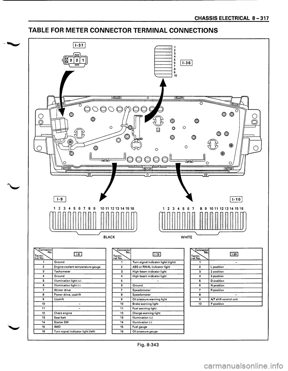
CHASSIS ELECTRICAL 8-317
TABLE FOR METER CONNECTOR TERMINAL CONNECTIONS
~-""""""', 1----""'12 1----""'1! 6 1----l 6 [Iill
1----""'1 ~ 9 1---""'l,o
®
0 0
0
® @
0 0 ~
~m© © © © ©'--m ~~0
0 !III
1 2 3 4 5 6 7 8 9 1011 1213141516 1 2 3 4 56 7 8 9 10111213141516
w~~~~~~~~ ~~~~~~m rn~~~~~~ ~~nn~~m
~ I J BLACK WHITE
~r o. DTI -na No. ~
. IJJ:Q] -
. ~ [ill] . -. 1 Ground 1 Turn
signal indicator light (right)
1 -2 Engine coolant temperature gauge 2 ABS or RWAL indicator light 2 L
position
3 Tachometer 3 High-beam indicator light 3 2 position 4
Ground
4 High-beam
indicator light 4 3 position 6 Illumination light (+I 5 -5 D position
6 Illumination light(-) 6 Ground 6 N position 7 Winter drive 7 Speedometer 7 R position 8 Power drive, upshift 8 Speedometer 8 -9 Upshift 9 Oil pressure warning light 9 AfT shift control unit 10 -10 Brake warning light 10 P position 11 -11 Fuel warning light 12 Check engine 12 Charge warning light 13 Seat belt 13 Illumination (+) 14 StarterSW 14 Illumination (-) 15 4WD 15 Fuel gauge 16 Turn signal indicator light (left) 16 Oil pressure gauge
Fig. 8-343
Page 1523 of 1928
1. Fuel tank
• Refer to fuel tank removal steps in Section 6C
"ENGINE FUEL."
2. Fuel tank unit
• Disconnect the connectors.
• Remove the five screws.
B INSTALLATION
To install, follow the removal steps in the reverse
order.
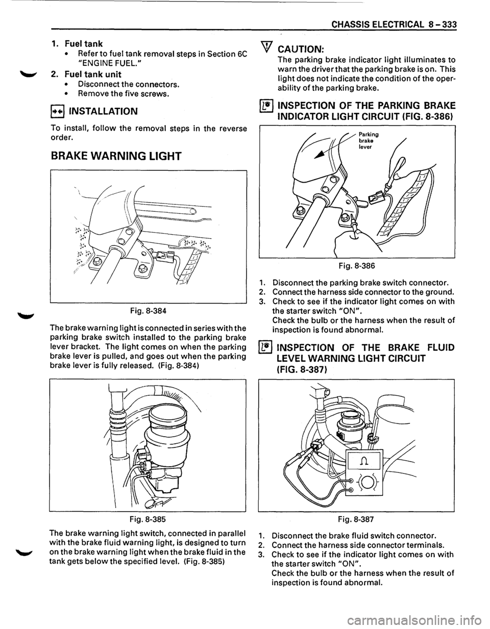
BRAKE WARNING LIGHT
Fig. 8-384
The brake
warning light is connected in series with the
parking brake switch
installed to the parking brake
lever bracket. The
light comes on when the parking
brake lever is
pulled, and goes out when the parking
brake lever is
fully released. (Fig. 8-384)
Fig. 8-385
The brake warning
light switch, connected in parallel
with the brake fluid warning light, is designed to turn
on the brake warning light when the brake fluid in the
tank gets
below the specified level. (Fig. 8-385)
CHASSIS ELECTRICAL 8-333
"f CAUTION:
The parking brake indicator light illuminates to
warn the driver that the parking brake is on. This
light does not indicate the condition of the oper
ability of the parking brake.
~ INSPECTION OF THE PARKING BRAKE
INDICATOR LIGHT CIRCUIT (FIG. 8-386)
Fig. 8-386
1. Disconnect the parking brake switch connector.
2. Connect the harness side connector to the ground.
3. Check to see if the indicator light comes on with
the starter switch "ON".
Check the bulb or the harness when the result of
inspection is found abnormal.
~ INSPECTION OF THE BRAKE FLUID
LEVEL WARNING LIGHT CIRCUIT
(FIG.
8-387)
Fig. 8-387
1. Disconnect the brake fluid switch connector.
2. Connect the harness side connector terminals.
3. Check to see if the indicator light comes on with
the starter switch "ON".
Check the bulb or the harness when the result of
inspection is found abnormal.
Page 1524 of 1928
8-334 CHASSIS ELECTRICAL
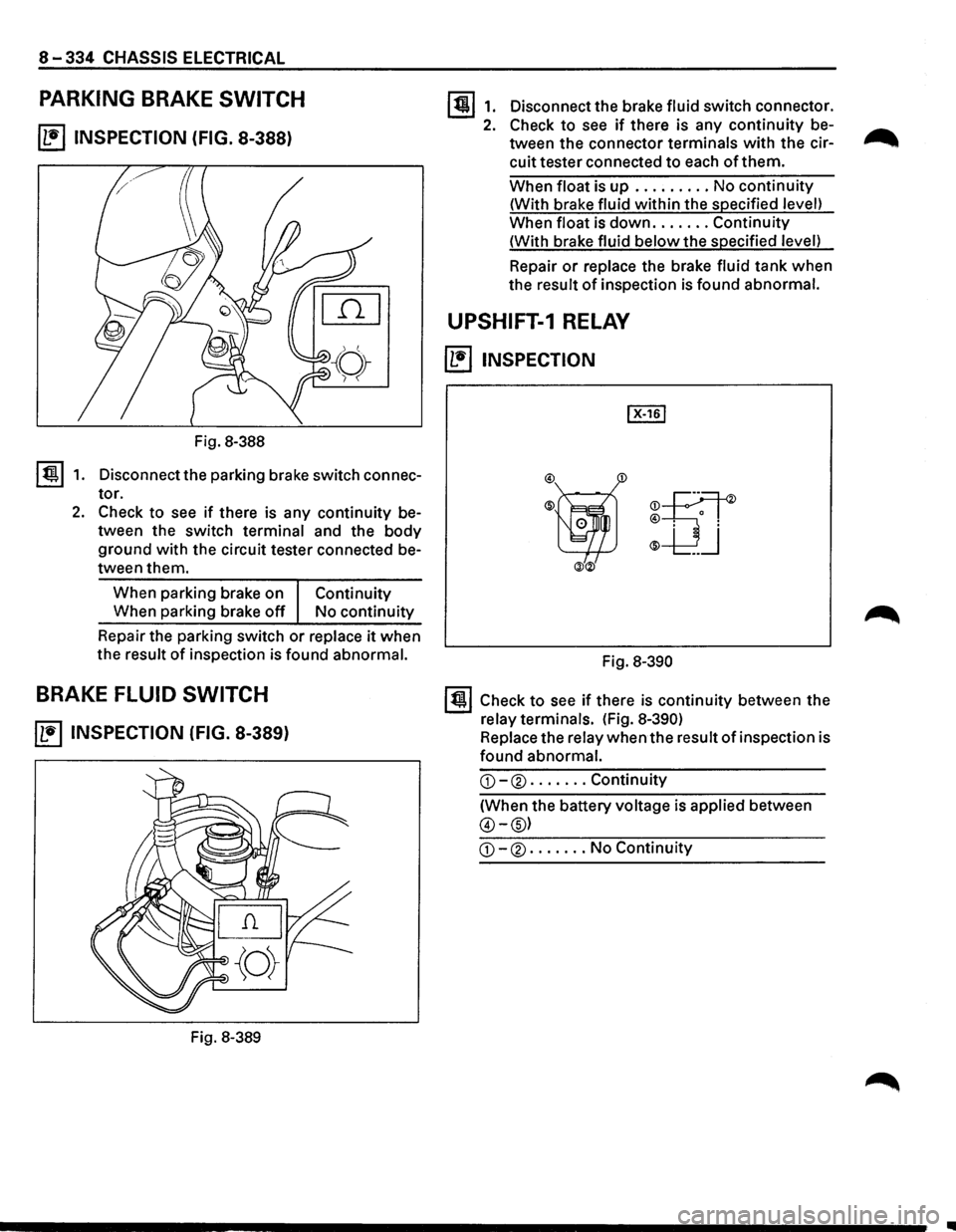
PARKING BRAKE SWITCH
~ INSPECTION (FIG. 8-388)
Fig. 8-388
I ti!!.l 1. Disconnect the parking brake switch connec
tor.
2. Check to see if there is any continuity be
tween the switch terminal and the
body
ground with the circuit tester connected be
tween them.
When parking brake on
Continuity
When parking brake off No continuity
Repair the parking switch
or replace it when
the result
of inspection is found abnormal.
BRAKE FLUID SWITCH
~ INSPECTION (FIG. 8-389)
Fig. 8-389
1311. Disconnectthebrakefluidswitchconnector.
2. Check to see if there is any continuity be-...-...
tween the connector terminals with the cir--..
cuit tester connected to each of them.
When float is up ......... No continuity
(With brake fluid within the specified level)
When float is
down ....... Continuity
(With brake fluid
below the specified level)
Repair
or replace the brake fluid tank when
the result
of inspection is found abnormal.
UPSHIFT-1 RELAY
~ INSPECTION
®ijf ®
-UJ
ill®
Fig. 8-390
131 Check to see if there is continuity between the
relay terminals. (Fig.
8-390)
Replace the relay when the result of inspection is
found abnormal.
G)-® ....... Continuity
(When the battery voltage is applied between
@-@)
G)-® ....... No Continuity
..
Page 1585 of 1928
---------------~-~---
CRUISE CONTROL 9B-1
SECTION 98
CRUISE CONTROL
CONTENTS
General description ................................ .
Parts location .......................................... .
Circuit diagram ....................................... .
Diagnosis ................................................. .
On-vehicle service ................................. ..
Brake switch adjustment ................ ..
Clutch switch adjustment ................ .
Actuator
cable adjustment .............. .
Starter switch ................................... .
Cruise control main switch .............. .
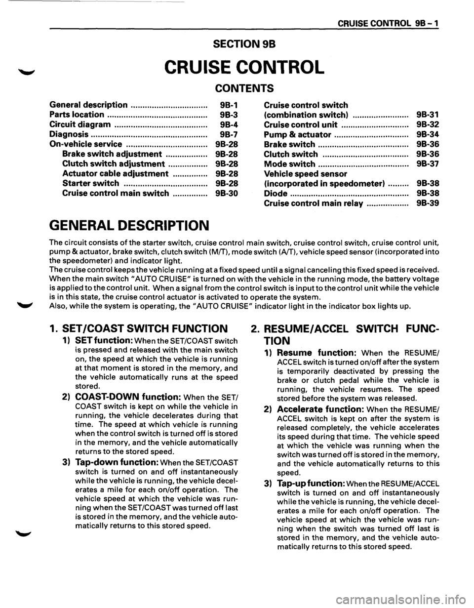
GENERAL DESCRIPTION
98-1
9B-3
98-4
9B-7
98-28
9B-28
9B-28
9B-28
9B-28
9B-30 Cruise
control
switch
(combination switch) ........................ 98-31
Cruise control unit .......................... ... 9B-32
Pump
& actuator .................. .............. 9B-34
Brake switch ....................................... 9B-36
Clutch switch .............................. ....... 9B-36
Mode switch .. .. .. .. .. .. .. .. .. .. .. .. .. .. .. .. .. .. .. . 9B-37
Vehicle speed sensor
(incorporated in speedometer) ......... 9B-38
Diode
.. .. .. .. .. .. . .. .. .. .. .. . .. .. .. .. .. .. .. .. .. .. . .. .. .. 9B-38
Cruise control main relay .................. 9B-39
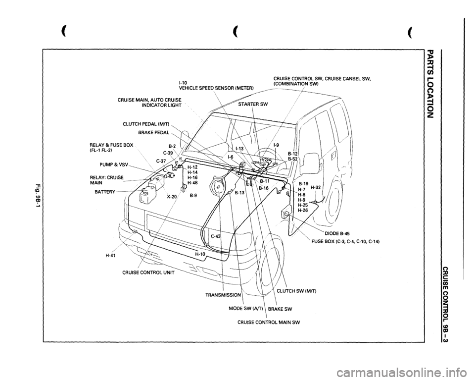
The circuit consists of the starter switch, cruise control main switch, cruise control switch, cruise control unit,
pump &actuator, brake switch, clutch switch (M/T), mode switch (A/T), vehicle speed sensor (incorporated into
the speedometer) and indicator light.
The cruise control keeps
the vehicle running at a fixed speed until a signal canceling this fixed speed is received.
When the main switch "AUTO CRUISE" is turned on with the vehicle in the running mode, the battery voltage
is applied
to the control unit. When a signal from the control switch is input to the control unit while the vehicle
is in this state, the cruise control actuator is activated to operate the system .
.._, Also, while the system is operating, the "AUTO CRUISE" indicator light in the indicator box lights up.
1. SET /COAST SWITCH FUNCTION
1) SET function: When the SET/COAST switch
is pressed and released
with the main switch
on, the speed at
which the vehicle is running
at that moment is stored in the memory, and
the vehicle
automatically runs at the speed
stored.
2) COAST-DOWN function: When the SET/
COAST switch is kept on while the vehicle in
running, the vehicle decelerates
during that
time. The speed at which vehicle is running
when the control switch is turned off is stored
in the
memory, and the vehicle automatically
returns
to the stored speed.
3) Tap-down function: When the SET/COAST
switch is turned on and off instantaneously
while the vehicle is running, the vehicle decel
erates a mile for each on/off operation. The
vehicle speed at
which the vehicle was run
ning when the SET/COAST was turned off last
is stored in the
memory, and the vehicle auto
matically returns to this stored speed.
2. RESUME/ ACCEL SWITCH FUNC
TION
1) Resume function: When the RESUME/
ACCEL switch is turned
on/off after the system
is
temporarily deactivated by pressing the
brake or clutch pedal while the vehicle is
running,
the vehicle resumes. The speed
stored before the system
was released.
2) Accelerate function: When the RESUME/
ACCEL switch is kept on after the system is
released completely, the vehicle accelerates
its speed
during that time. The vehicle speed
at
which the vehicle was running when the
switch
was turned off is stored in the memory,
and the vehicle automatically returns to this
speed.
3) Tap-up function: When the RESU ME/ACCEL
switch is
turned on and off instantaneously
while the vehicle is running, the vehicle decel
erates a mile for each on/off operation. The
vehicle speed at
which the vehicle was run
ning when the switch was turned off last is
stored in the
memory, and the vehicle auto
matically returns to this stored speed.
Page 1586 of 1928
98-2 CRUISE CONTROL
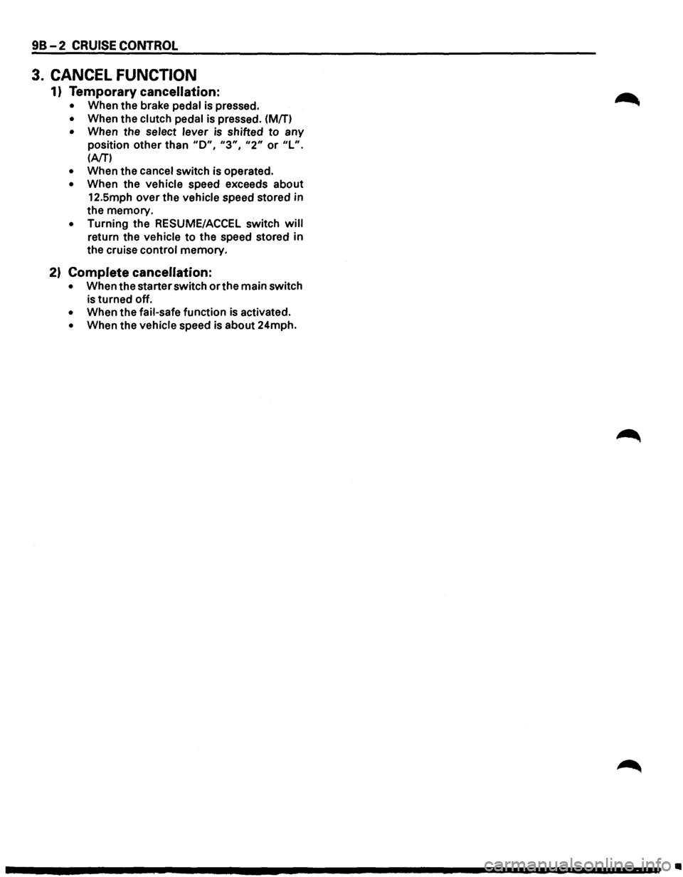
3. CANCEL FUNCTION
1) Temporary cancellation:
• When the brake pedal is pressed.
• When the clutch pedal is pressed. (Mfn
• When the select lever is shifted to any
position other than
"D", "3", "2" or "L".
(AfT')
• When the cancel switch is operated.
• When the vehicle speed exceeds about
12.5mph over the vehicle speed stored in
the memory.
• Turning the RESUME/ACCEL switch will
return the vehicle to the speed stored in
the cruise control memory.
2) Complete cancellation:
• When the starter switch or the main switch
is turned off.
• When the fail-safe function is activated.
• When the vehicle speed is about 24mph.
Ill
Page 1587 of 1928
, cCi" <0 CD I ....
( (
1-10
CRUISE CONTROL SW,
CRUISE
CANSEL SW,
!COMBINATION
SWl
VEHICLE
SPEED
SENSOR
!METER}
i
CRUISE MAIN, AUTO CRUISE
INDICATOR LIGHT
CLUTCH
PEDAL
IM[T)
~
. //
BRAKE PEDAL
~~
RELAY &
FUSE BOX
B-2
vi"""
(FL-1
FL-2}
C-3g\j;~
PUMP&VSV
RELAY:
CRUISE
MAIN BATTERY--
/
H-41
··,.
,:-,
\
·.,"-
~DIODE
8-45
'"-FUSE
BOX IC-3, C-4, C-10,
C-14)
CRUISE
CONTROL
MAIN
SW
(
~ ~ 0 n ~ 0 z
n ::D c c;; m n 0 ~ 0 r-fD OJ I w
Page 1592 of 1928
98-8 CRUISE CONTROL
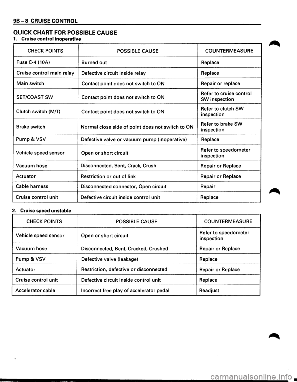
QUICK CHART FOR POSSIBLE CAUSE
1. Cruise control inoperative
CHECK POINTS POSSIBLE CAUSE
Fuse C-4 (10A) Burned out
Cruise control main relay Defective circuit inside relay
Main switch
Contact point does not switch to ON
SET/COAST SW Contact point does not switch to ON
Clutch switch (M/T)
Contact point does not switch to ON
Brake switch Normal close side of point does not switch to ON
Pump & VSV Defective valve or vacuum pump (inoperative)
Vehicle speed sensor Open or short circuit
Vacuum hose Disconnected, Bent, Crack, Crush
Actuator Restriction
or out of link
Cable
harness Disconnected connector, Open circuit
Cruise
control unit Defective circuit inside control unit
2. Cruise speed unstable
CHECK POINTS POSSIBLE CAUSE
Vehicle
speed sensor Open or short circuit
Vacuum hose
Disconnected, Bent, Cracked, Crushed
Pump & VSV Defective valve (leakage)
Actuator Restriction,
defective or disconnected
Cruise
control unit Defective circuit inside control unit
Accelerator cable
Incorrect free play of accelerator pedal COUNTERMEASURE
Replace
Replace
Repair or replace
Refer to cruise control
SW
inspection
Refer
to clutch SW
inspection
Refer
to brake SW
inspection
Replace
Refer to speedometer
inspection
Repair
or Replace
Repair or Replace
Repair
Replace
COUNTERMEASURE
Refer to speedometer
inspection
Repair
or Replace
Replace
Repair or Replace
Replace
Readjust
•
Page 1593 of 1928
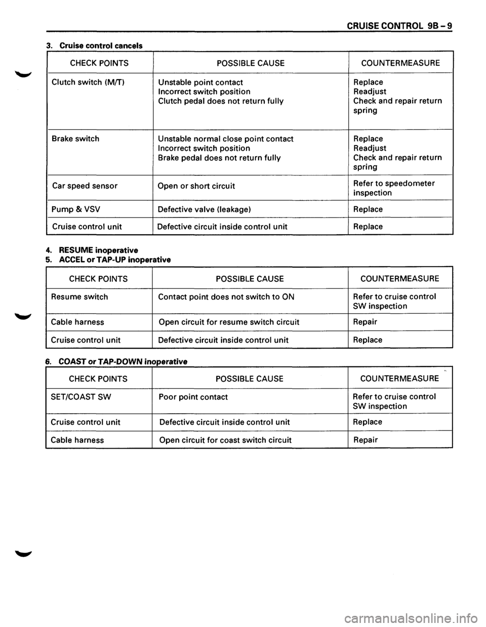
-------------------
CRUISE CONTROL 98-9
3. Cruise control cancels
CHECK POINTS POSSIBLE CAUSE COUNTERMEASURE
Clutch switch
(M/T) Unstable point contact Replace
Incorrect
switch position Readjust
Clutch
pedal does not return fully Check and repair return
spring
Brake switch
Unstable normal close point contact Replace
Incorrect
switch position Readjust
Brake
pedal does not return fully Check and repair return
spring
Car speed sensor
Open or short circuit Refer to speedometer
inspection
Pump& VSV Defective valve (leakage) Replace
Cruise control unit Defective circuit inside control unit Replace
4. RESUME inoperative
5. ACCEL or TAP-UP inoperative
CHECK POINTS POSSIBLE CAUSE COUNTERMEASURE
Resume switch
Contact
point does not switch to ON Refer to cruise control
SW
inspection
Cable harness Open circuit for resume switch circuit Repair
Cruise
control unit Defective circuit inside control unit Replace
6 COAST or TAP-DOWN inoperative ,,
CHECK POINTS POSSIBLE CAUSE COUNTERMEASURE
SET/COAST
SW Poor point contact Refer to cruise control
SW
inspection
Cruise
control unit Defective circuit inside control unit Replace
Cable
harness Open circuit for coast switch circuit Repair
Page 1594 of 1928
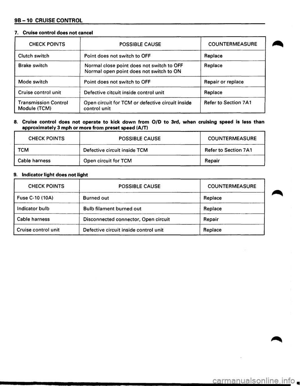
98-10 CRUISE CONTROL
7. Cruise control does not cancel
CHECK POINTS POSSIBLE CAUSE COUNTERMEASURE
Clutch switch Point does not switch to OFF Replace
Brake switch
Normal close point does not switch to OFF Replace
Normal open point does not switch to ON
Mode switch Point does not switch to OFF Repair or replace
Cruise control unit
Defective citcuit inside control unit Replace
Transmission Control Open circuit for TCM or defective circuit inside Refer to Section
7 A 1
Module (TCM) control unit
8. Cruise control does not operate to kick down from 0/D to 3rd, when cruising speed is less than
approximately 3 mph or more from preset speed (A/T)
CHECK POINTS POSSIBLE CAUSE COUNTERMEASURE
TCM Defective circuit inside TCM Refer
to Section 7 A 1
Cable harness Open circuit for TCM
Repair
9. Indicator light does not light
CHECK POINTS POSSIBLE CAUSE COUNTERMEASURE
Fuse
C-10 (10A) Burned out Replace
Indicator
bulb Bulb filament burned out Replace
Cable
harness Disconnected connector, Open circuit Repair
Cruise
control unit Defective circuit inside control unit Replace
..