brake ISUZU TROOPER 1995 Workshop Manual
[x] Cancel search | Manufacturer: ISUZU, Model Year: 1995, Model line: TROOPER, Model: ISUZU TROOPER 1995Pages: 1928
Page 1050 of 1928
7A-178 AUTOMATIC TRANSMISSION (4L30-E)
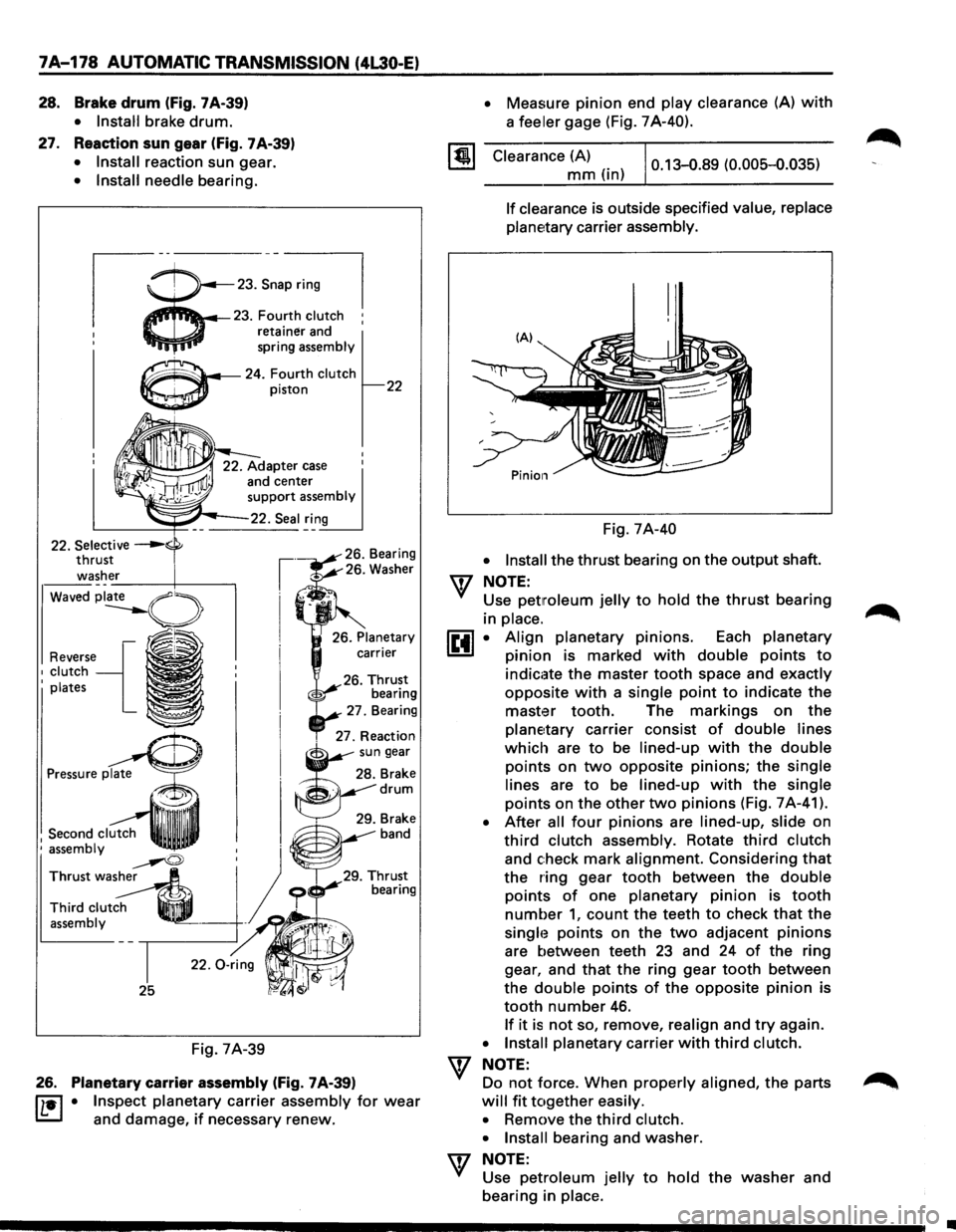
28. Brake drum (fig. 7 A-39)
27.
• Install brake drum.
Reaction sun gear (Fig. 7A-39)
• Install reaction sun gear.
• Install needle bearing.
23.S~a=l
4'i'fl._.l4--23. Fourth clutch :
retainer and
spring
assembly
~~..,...~---24. Fourth clutch
Waved
Reverse{ 1 clutch I plates
1 Second clutch ' assembly
~ Thrust wash~
Third clut~ q_ assembly .
25
Fig. 7A-39
piston
26. Planetary carrier assembly (Fig. 7 A-39)
22
IL•I • Inspect planetary carrier assembly for wear
and damage, if necessary renew.
• Measure pinion end play clearance (A) with
a feeler gage (Fig. 7A-40).
Clearance (A)
mm (in) 0.13-0.89 (0.005-0.035)
If clearance
is outside specified value, replace
planetary
carrier assembly.
Fig. 7A-40
• Install the thrust bearing on the output shaft.
\f NOTE:
Use petmleum jelly to hold the thrust bearing
in
place.
~·
•
Align planetary pinions. Each planetary
pinion is marked with double points to
indicate the master tooth space and exactly
opposite with a single point to indicate the
master tooth. The markings on the
planetary carrier consist of double lines
which are to be lined-up with the double
points on two opposite pinions; the single
lines
are to be lined-up with the single
points on the other two pinions (Fig. 7 A-41 ).
After all four pinions are lined-up, slide on
third clutch assembly. Rotate third clutch
and check mark alignment. Considering that
the ring gear tooth between the double
points of one planetary pinion is tooth
number 1, count the teeth to check that the
singh~ points on the two adjacent pinions
are between teeth 23 and 24 of the ring
gear, and
that the ring gear tooth between
the
double points of the opposite pinion is
tooth number 46.
If it is not so, remove, realign and try again.
• Install planetary carrier with third clutch.
\f NOTE:
Do not force. When properly aligned, the parts
will fit together easily.
•
Remove the third clutch.
• Install
bearing and washer.
\f NOTE:
Use petroleum jelly to hold the washer and
bearing in
place.
•
Page 1057 of 1928
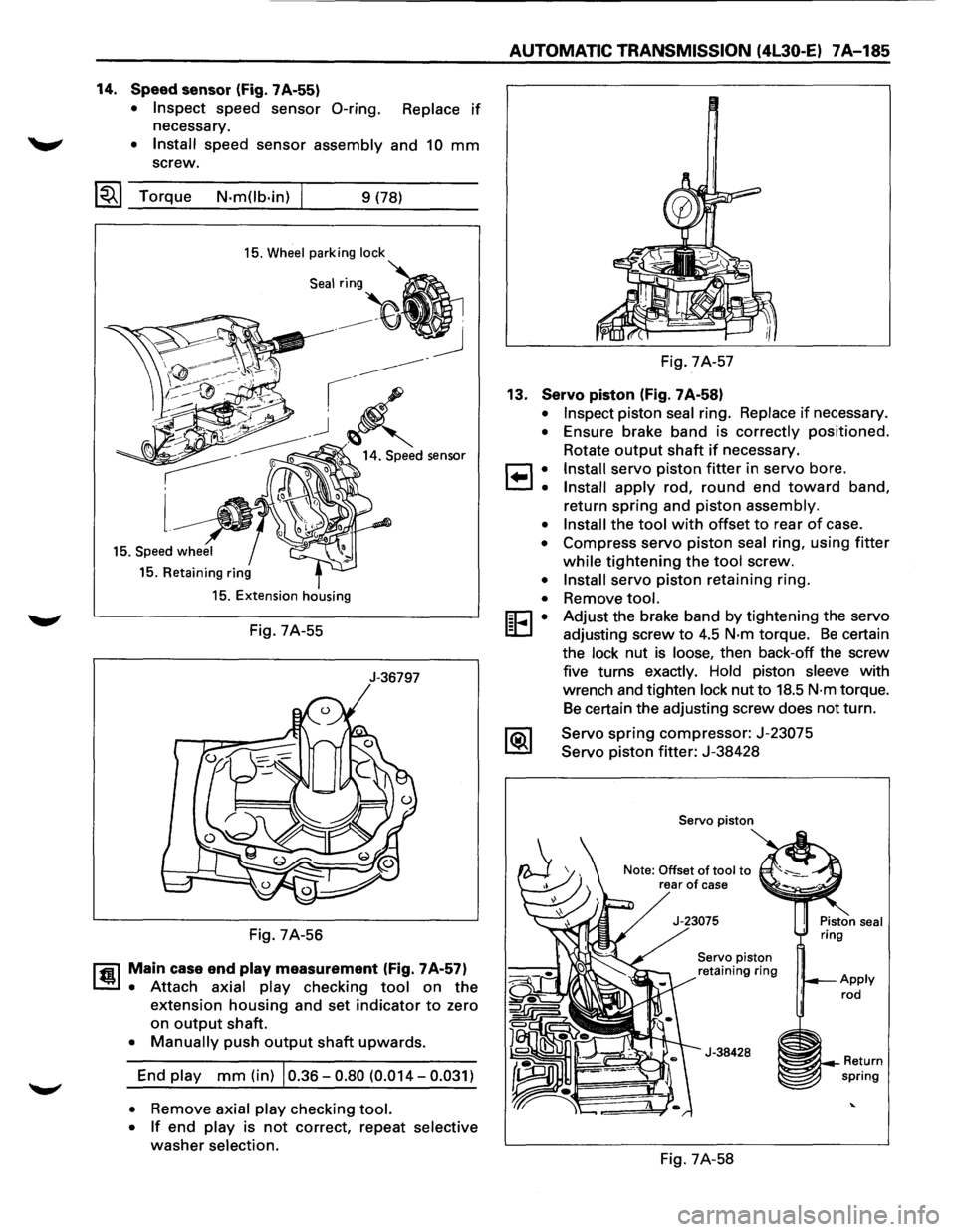
14. Speed sensor (Fig. 7A-55)
• Inspect speed sensor 0-ring. Replace if
necessary.
~ • Install speed sensor assembly and 10 mm
screw.
~~~ Torque N-m(lb-in) 9 (78)
15. Wheel parking lock
15. Retaining ring
15. Extension housing
Fig. 7A-55
J-36797
Fig. 7A-56
rfil Main case end play measurement (Fig. 7A-57)
~ • Attach axial play checking tool on the
extension housing and set indicator to zero
on
output shaft.
• Manually push output shaft upwards.
End play mm (in) 10.36-0.80 (0.014-0.031)
• Remove axial play checking tool.
• If end play is not correct, repeat selective
washer selection.
AUTOMATIC TRANSMISSION (4l30-E) 7A-185
Fig. 7A-57
13. Servo piston (Fig. 7A-58)
•
•
8:
•
•
•
•
[E•
Inspect piston seal ring. Replace if necessary .
Ensure brake band is correctly
positioned .
Rotate
output shaft if necessary.
Install servo piston fitter in servo bore.
Install apply rod, round end toward band,
return
spring and piston assembly.
Install the tool with offset to rear of case .
Compress servo
piston seal ring, using fitter
while tightening the tool screw.
Install servo piston retaining ring .
Remove
tool.
Adjust the brake band by tightening the servo
adjusting screw
to 4.5 N-m torque. Be certain
the lock nut
is loose, then back-off the screw
five turns exactly. Hold piston sleeve with
wrench and tighten lock nut to
18.5 N-m torque.
Be certain the adjusting screw does not turn.
Servo
spring compressor: J-23075
Servo piston fitter: J-38428
Servo piston
Note: Offset
of tool to rear of case
Servo piston
retaining ring
J-38428
Fig. 7A-58
~~--Return spring
Page 1079 of 1928
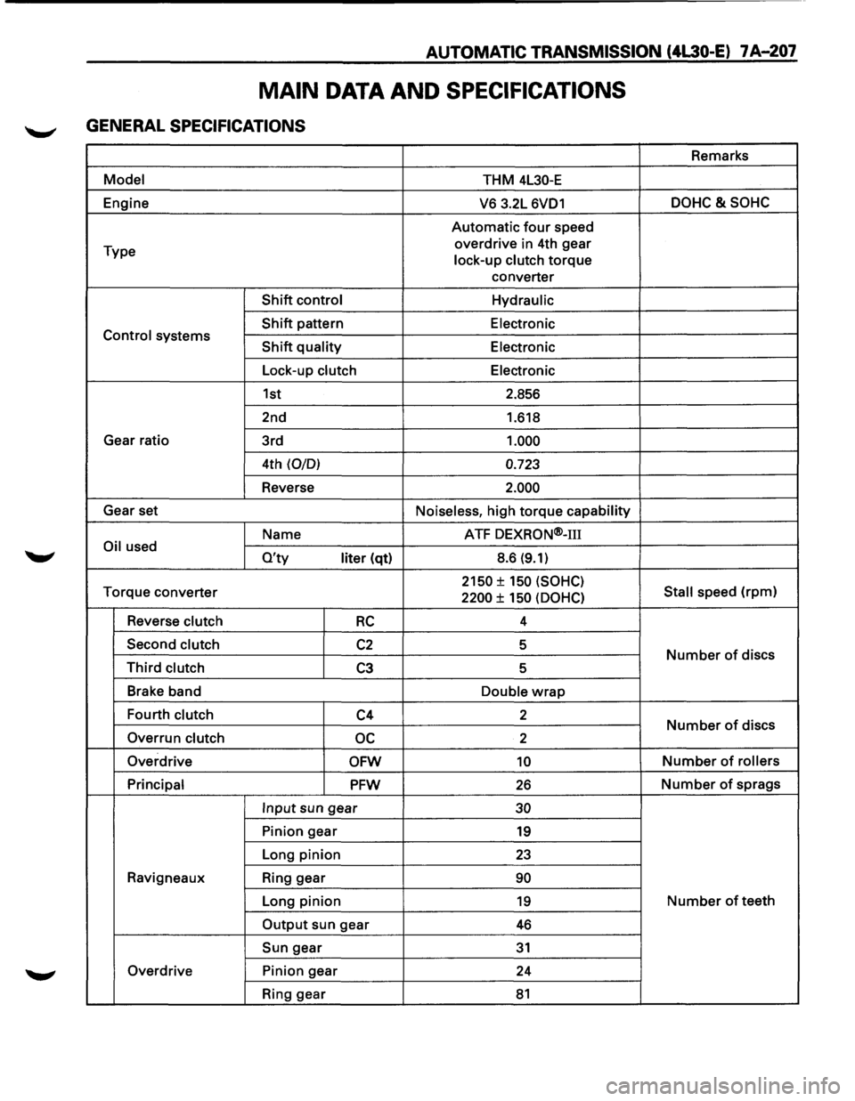
AUTOMATIC TRANSMISSION (4L30-E) 7 A-207
MAIN DATA AND SPECIFICATIONS
GENERAL SPECIFICATIONS
Remarks
Model THM 4L30-E
Engine
V6 3.2L 6VD1 DOHC&SOHC
Automatic four speed
Type overdrive
in 4th gear
lock-up clutch
torque
converter
Shift control Hydraulic
Shift pattern
Electronic Control systems Shift quality Electronic
Lock-up clutch Electronic
1st 2.856
2nd 1.618
Gear ratio
3rd
1.000
4th (0/0) 0.723
Reverse 2.000
Gear set
Noiseless, high torque capability
Name ATF
DEXRON®-m
Oil used O'ty liter (qt) 8.6 (9.1)
Torque
converter 2150 ± 150 (SOHC)
Stall speed (rpm) 2200 ± 150 (OOHC)
Reverse clutch RC 4
Second clutch
C2 5 Number of discs Third clutch C3 5
Brake band
Double
wrap
Fourth clutch C4 2 Number of discs
Overrun clutch oc 2
Overdrive
OFW 10 Number of rollers
Principal
PFW 26 Number of sprags
Input sun gear 30
Pinion gear 19
Long pinion 23
Ravigneaux Ring gear 90
Long pinion 19 Number of teeth
Output sun gear 46
Sun gear 31
Overdrive Pinion gear
24
Ring gear
81
Page 1090 of 1928
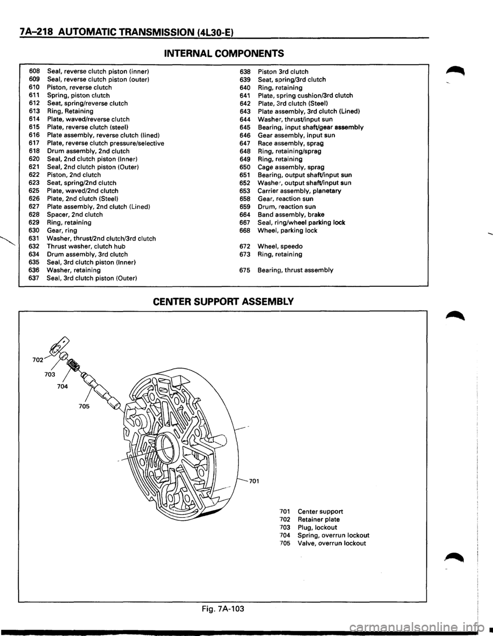
7A-218 AUTOMATIC TRANSMISSION (4L30-E}
608 Seal, reverse clutch piston (inner)
609 Seal, reverse clutch piston (outer)
610 Piston, reverse clutch 611 Spring, piston clutch 612 Seat, spring/reverse clutch 613 Ring, Retaining
614
Plate, waved/reverse clutch 615 Plate, reverse clutch (steel) 616 Plate assembly, reverse clutch (lined)
617 Plate, reverse clutch pressure/selective
618 Drum assembly, 2nd clutch
620 Seal, 2nd clutch piston (Inner) 621 Seal, 2nd clutch piston (Outer) 622 Piston, 2nd clutch
623 Seat, spring/2nd clutch 625 Plate, waved/2nd clutch 626 Plate, 2nd clutch (Steel)
627 Plate assembly, 2nd clutch (Lined)
628 Spacer, 2nd clutch 629 Ring, retaining
630 Gear, ring 631 Washer, thrust/2nd clutch/3rd clutch 632 Thrust washer, clutch hub
634 Drum assembly, 3rd clutch
635 Seal, 3rd clutch piston (Inner) 636 Washer, retaining
637 Seal, 3rd clutch piston (Outer)
INTERNAL COMPONENTS
638 Piston 3rd clutch 639 Seat, spring/3rd clutch
640 Ring, n~taining 641 Plate, spring cushion/3rd clutch 642 Plate, :::rd clutch (Steel) 643 Plate assembly, 3rd clutch (Lined)
644 Washer,
thrust/input sun
645 Bearino, input shaft/gear assembly 646 Gear assembly, input sun
647
Race assembly, sprag
648 Ring, mtaining/sprag
649 Ring,
mtaining 650 Cage a:;sembly, sprag 651 Bearinn, output shaft/input sun
652 Washer, output shaft/input sun
653 Carrier assembly, planetary 658 Gear, reaction sun
659 Drum, 1·eaction sun
664 Band
assembly, brake 667 Seal, ring/wheel parking lock 668 Wheel, parking lock
672 Wheel, speedo
673 Ring, rEttaining
675
Bearin~1. thrust assembly
CENTER SUPPORT ASSEMBLY
701
Fig. 7A-103
701 Center support 702 Retainer plate
703 Plug, lockout
704 Spring,
overrun lockout
705 Valve,
overrun lockout
•
Page 1149 of 1928
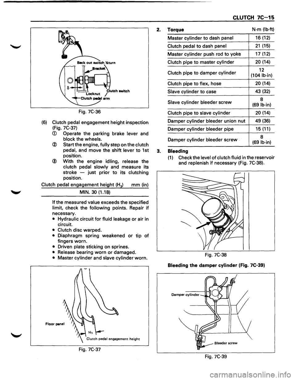
Fig. 7C-36
(6) Clutch pedal engagement height inspection
(Fig.
7C-37)
® Start the engine, fully step on the clutch
pedal,
and move the shift lever to 1st
position.
@ With the engine idling, release the
clutch pedal slowly and measure its
stroke -just prior
to its clutching
position.
Clutch pedal engagement height (H3) mm (in)
MIN. 30 (1.18)
If the
measured value exceeds the specified
limit, check the following points. Repair if
necessary.
• Hydraulic circuit for fluid leakage or air in
circuit.
• Clutch disc warped.
• Diaphragm spring weakened or tip of
fingers worn.
• Driven plate sticking on sprines.
• Release bearing worn or damaged.
• Master cylinder and slave cylinder worn.
Floor panel
Fig. 7C-37
CLUTCH 7C-15
2. Torque N·m (lb·ft)
Master cylinder to dash panel 16 (12)
Clutch pedal to dash panel 21 (15)
Master cylinder push rod to yoke 17 (12)
Clutch pipe to master cylinder 20 (14)
Clutch pipe
to damper cylinder 12
(104 lb·in)
Clutch
pipe to flex, hose 20 (14)
Slave cylinder to case 43 (32)
Slave
cylinder bleeder screw 8 (691b·in)
Clutch
pipe to slave cylinder 20 (14)
Damper cylinder bleeder union nut 49 (36)
Damper cylinder bleeder pipe 15 (11)
Damper cylinder
bleeder screw 8 (69 lb·in)
3. Bleeding
(1) Check
the level of clutch fluid in the reservoir
and
replenish if necessary (Fig. 7C-38).
Fig. 7C-38
Bleeding the damper cylinder (Fig. 7C-39)
Damper cylinder
Fig. 7C-39
Page 1152 of 1928

7C-18 CLUTCH
Fig. 7C-43
Fig. 7C-44
SLAVE CYLINDER
~\
4
5
3
l•!•l REASSEMBLY
To reassemble, follow the disassembly steps in the
reverse
order, noting the following points:
1. Cylinder body
D • lmmHrse the cylinder body in clean brake fluid
L:::J (Fig. 7C-45).
2. Piston assembly
D Before installing, apply a thin coat of rubber
L:::J grease to the piston. Install cup in groove in
IE41 piston with the lip turned to front of cylinder.
Use care to prevent damaging the lip of the piston
seat.
Fig.
7C-45
Disassembly steps
1. Boot
2. Push rod
3. Piston and piston
cup 4. Spring
5. Cylinder body
Reassembly steps
To reassemble, follow the disassembly steps in the reverse order.
Fig. 7C-46
•
Page 1191 of 1928

CHASSIS ELECTRICAL 8-1
·SECTION 8
CHASSIS ELECTRICAL
'\f CAUTION: .
When fasteners are removed, always reinstall them at the same location from which they were removed.
If a fastener needs to be replaced, use the correct part number fastener for that application. If the correct
part number fastener is not
available, a fastener of equal size and strength (or stronger) may be used.
Fasteners that are not reused, and those requiring thread
locking compound, will be called out. The correct
torque
values must be used when installing fasteners that require it. If the above conditions are not
followed, parts or system damage could result.
CONTENTS
General Information .................................... 8-2
Notes for Working on Electrical
Items .................................................... 8-2
Symbols and Abbreviations ................. 8-8
Symbols ............................................ 8-8
Abbreviations ................................... 8-9
Parts for Electrical Circuit ..................... 8-10
Wiring ............................................... 8-10
Fuse .................................................. 8-11
Fusible Link ....................................... 8-12
Circuit Breaker ................................... 8-12
Relay ................................................. 8-12
Relay Specifications and
Configurations ................................ 8-13
Diode ................................................. 8-14
Connector ......................................... 8-15
Reading the Circuit Diagram ................ 8-17
Main Data and Specifications .................... 8-19
Bulb Specifications ................................ 8-19
Fuse,
Fusible Link and
Circuit Breaker Location ..................... 8-21
Fuse
Block Circuit .................................. 8-22
Reference Table of Fuse, Fusible
Link and Circuit Breaker ..................... 8-23
Relay Location ....................................... 8-27
Diode Location .......................................
8-28
Grounding Point .................................... 8-29
Reference Table ................................ 8-29
Location ............................................ 8-31
Cable Harness Routing .......................... 8-34
System Repair .............................................. 8-38
Start and Charging ................................ 8-38
Engine Control Module
(ECM) ................................................... 8-47
Headlight and Fog Light ........................ 8-58
Front Side Marker Light, Parking Light,
Taillight, License Plate Light and
Illumination Light .............................. 8-76
Stoplight and Rear Defogger .............. 8-92
Turn Signal Light, Hazard
Warning
Light, Cornering Light,
Backup
Light and Horn ..................... 8-106
Dome Light, Luggage room Light,
Courtesy Light, Map Light,
Seat Belt Switch and
Warning Buzzer ................................. 8-128
Power Door Lock ................................. 8-142
Power
Window .................................... 8-156
Cruise
Control ...................................... 8-172
Anti-Lock Brake
System (ABS) ........... 8-178
Rear
Wheel Anti-Lock Brake
System (RWAL) ................................. 8-185
Transmission
Control Module
(TCM) ................................................. 8-192
A/T Shift Lock ...................................... 8-200
Windshield
Wiper/Washer and
Rear
Wiper/Washer .......................... 8-205
Headlight wiper /washer ..................... 8-232
Audio, Auto Antenna,
Cigarette
Lighter and digital clock ... 8-246
Power Door Mirror ............................... 8-254
Anti-theft System ................................ 8-270
Meter and Warning/Indicator Light ... 8-288
A/T Shift Indicator ............................... 8-336
Heater and
Air Conditioning ............... 8-340
Sun
Roof ............................................... 8-346
Power Seat ........................................... 8-360
Seat
Heater .......................................... 8-37 4
Supplemental Restraint
System (SRS) -AIR BAG ................... 8-382
Page 1199 of 1928
CHASSIS ELECTRICAL 8-9
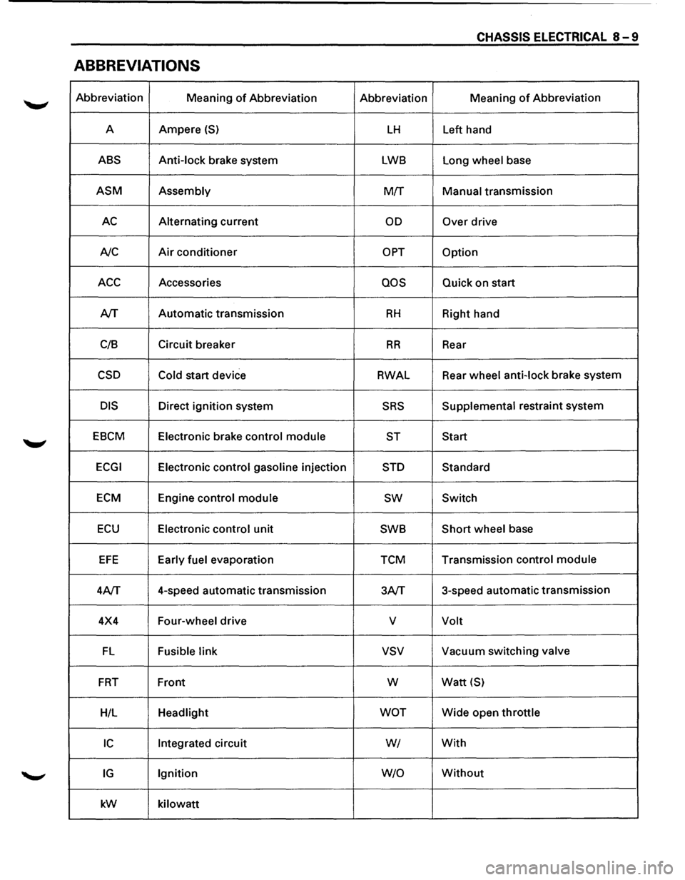
ABBREVIATIONS
Abbreviation
Meaning of Abbreviation Abbreviation Meaning of Abbreviation
A Ampere
(S) LH Left
hand
ABS Anti-lock brake system LWB Long wheel base
ASM Assembly M!f Manual transmission
AC Alternating current OD Over drive
A/C
Air conditioner OPT Option
ACC Accessories QOS Quick on start
A/T Automatic
transmission
RH Right hand
C/8 Circuit
breaker
RR Rear
CSD Cold start device RWAL Rear
wheel anti-lock brake system
DIS Direct ignition system SRS Supplemental restraint system
EBCM Electronic brake control module
ST Start
ECGI Electronic control gasoline injection STD Standard
ECM Engine control module sw Switch
ECU Electronic control unit SWB Short wheel
base
EFE Early fuel evaporation TCM Transmission
control module
4A/T 4-speed
automatic transmission
3A/T 3-speed
automatic transmission
4X4 Four-wheel drive
v Volt
FL Fusible link vsv Vacuum switching valve
FRT Front w Watt {S)
H/L Headlight WOT Wide open throttle
IC Integrated circuit WI With
IG Ignition W/0 Without
kW
kilowatt
Page 1207 of 1928
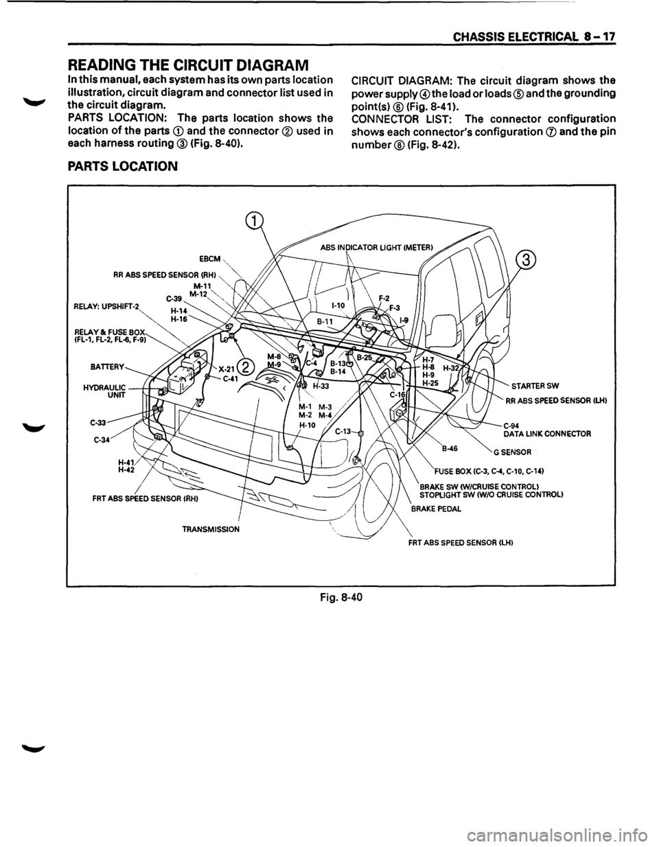
READING THE CIRCUIT DIAGRAM
In this manual, each system has its own parts location
illustration,
circuit diagram and connector list used in
the circuit diagram.
PARTS LOCATION: The parts location shows the
location of the parts CD and the connector® used in
each harness routing ® (fig. 8-40).
PARTS LOCATION
EBCM-,
RR ABS SPEED SENSOR (RHI "',~ M-11 ,,
C-39 M-12~'-, RELAY: UPSHIFT-2 ~
CHASSIS ELECTRICAL 8-17
CIRCUIT DIAGRAM: The circuit diagram shows the
powersupply@the load or loads® and the grounding
point(s)
® (Fig. 8-41 ).
CONNECTOR LIST: The connector configuration
shows
each connector's configuration (J) and the pin
number® (Fig. 8-42).
RELAY & FUSE BO~"'
7
~<-:;;;:~:~:_::0:;;::::'=l-\,.-..:._::::;;,...6
IFL-1, FL-2, FL-6, F-91 , "" ;;~~~~~~~;g~~k~
C-33
C-34
Fig. 8-40
STARTERSW
RR ABS SPEED SENSOR ILHI
C-94 DATA LINK CONNECTOR
GSENSOR
FUSE BOX IC-3, C-4, C-10, C-141
BRAKE SW IW/CRUISE CONTROL! STOPLIGHT SW (W/0 CRUISE CONTROL!
FRT ABS SPEED SENSOR ILHI
Page 1210 of 1928
8-20 CHASSIS ELECTRICAL
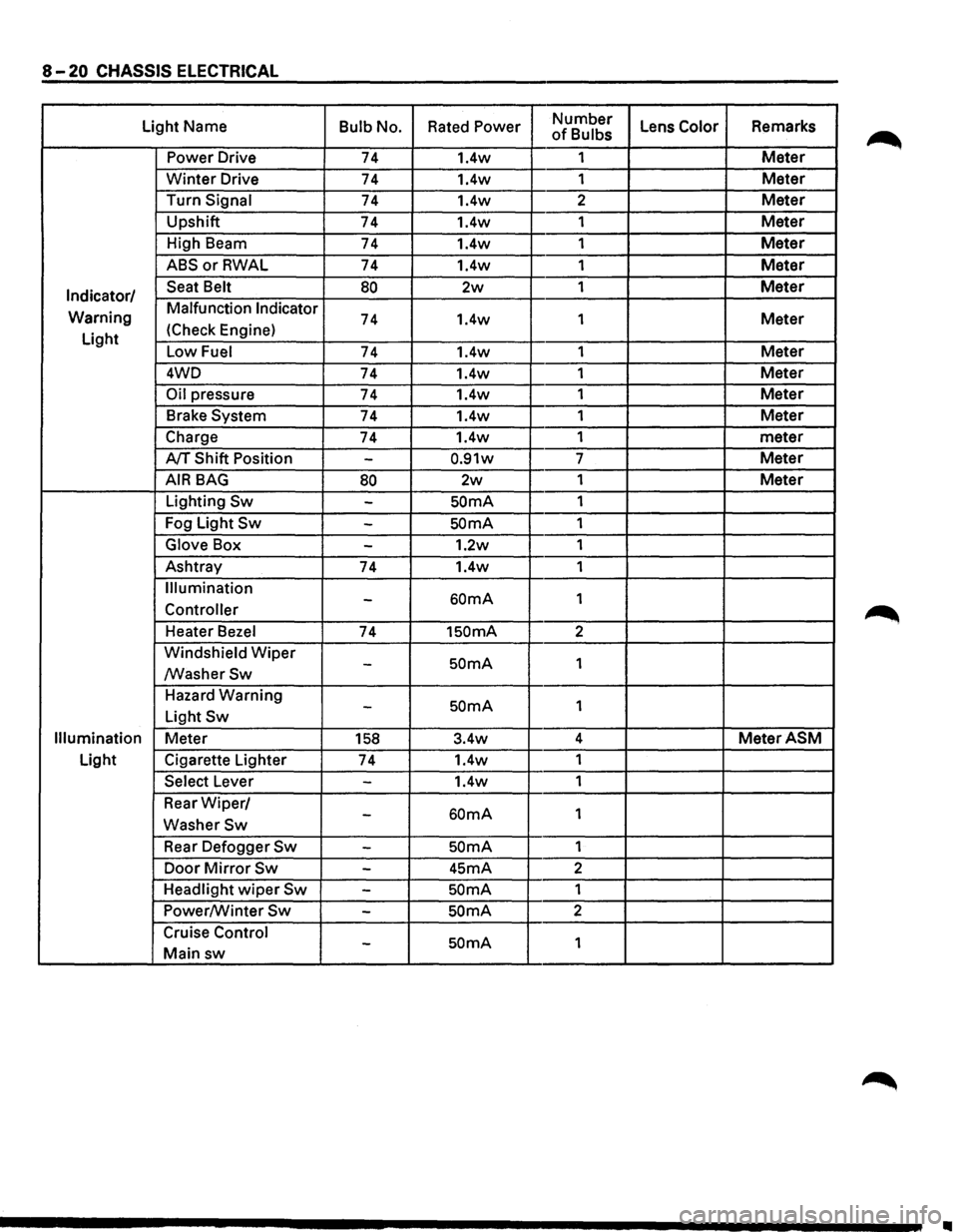
Light Name Bulb No. Rated Power Number Lens Color Remarks of Bulbs
Power Drive 74 1.4w 1
Meter
Winter Drive 74 1.4w
1 Meter
Turn Signal 74 1.4w 2 Meter
Upshift
74 1.4w 1 Meter
High Beam
74 1.4w 1 Meter
ABSorRWAL 74 1.4w 1 Meter
Indicator/ Seat Belt 80 2w 1 Meter
Warning Malfunction Indicator 74 1.4w
1 Meter
Light (Check
Engine)
Low Fuel 74 1.4w 1 Meter
4WD
74 1.4w 1 Meter
Oil pressure 74 1.4w 1 Meter
Brake System 74 1.4w 1 Meter
Charge 74 1.4w 1
meter
A/T Shift Position -0.91w 7 Meter
AIR BAG 80 2w 1 Meter
Lighting Sw -SOmA 1
Fog Light
Sw -SOmA 1
Glove Box -1.2w 1
Ashtray
74 1.4w 1
Illumination
60mA 1 -Controller
Heater Bezel 74 1SOmA 2
Windshield
Wiper SOmA 1 -/WasherSw
Hazard Warning SOmA 1 -Light Sw
Illumination Meter 158 3.4w 4 MeterASM
Light
Cigarette Lighter
74 1.4w
1
Select Lever -1.4w 1
Rear
Wiper/ 60mA 1 -WasherSw
Rear Defogger Sw -SOmA 1
Door
Mirror Sw -45mA 2
Headlight
wiper Sw -SOmA 1
Power/Winter
Sw -SOmA 2
Cruise Control
SOmA 1 -Main sw
II