brake ISUZU TROOPER 1995 Workshop Manual
[x] Cancel search | Manufacturer: ISUZU, Model Year: 1995, Model line: TROOPER, Model: ISUZU TROOPER 1995Pages: 1928
Page 1378 of 1928
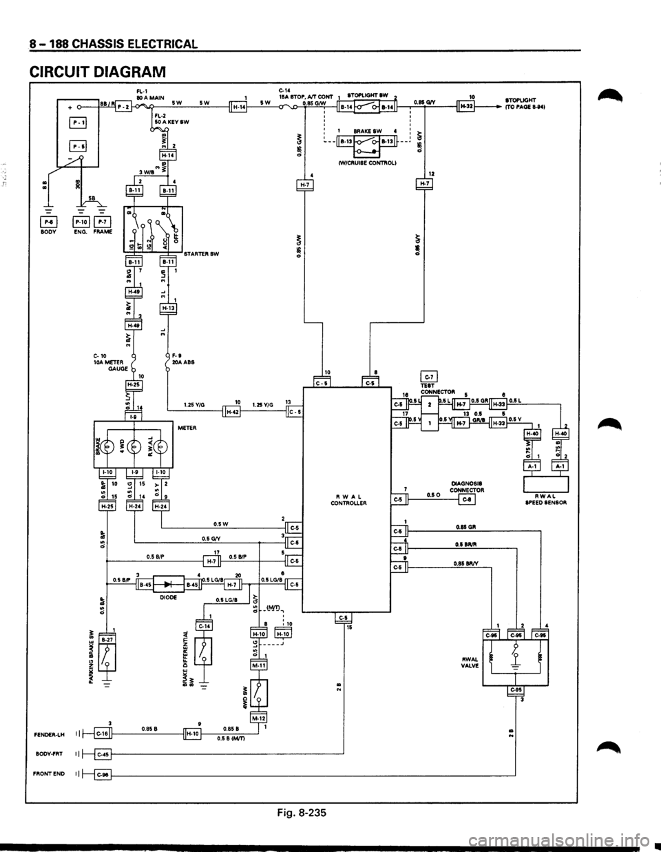
8-188 CHASSIS ELECTRICAL
CIRCUIT DIAGRAM
Ill Ill
+
B jP-toj~ BODY ENG. FRAME
3
FENOER-LH I I
BODY-FRT II
FRONTEND II
5W
F-9 20AABS
5W
1.25Y/G
METER
H-7
0
0 0
0
0.85 G1V
o I BRAKE SW 4 : ~ ~--~--~
~ ~ CW/CRUISE CONTROLI
12 H-7
Fig. 8-235
10 STOPLIGHT ITO PAGE 8-841
•
Page 1382 of 1928
8-192 CHASSIS ELECTRICAL
TRANSMISSION CONTROL MODULE (TCM)
GENERAL DESCRIPTION
The circuit consists of the starter switch, TCM, mode switch, brake switch, speed sensor, kick down switch,
Power and
Winter switches, Throttle Position (TP) sensor, Engine Control Module (ECM), barometer sensor,
adapter case, main case,
warning light (CHECK TRANS, NT OIL TEMP) and indicator light (WINTER DRIVE,
POWER DRIVE).
The TCM, based on the predetermined shifting characteristics and lockup operating valve, provides the
optimum shifting control to the varying vehicle running condition. The following input signals are sent to the
TCM: select lever position from the mode switch, running mode from the POWER & WINTER switches,
throttle opening from the TP sensor, vehicle speed from the vehicle speed sensor and engine speed from the
ECM are sent to the TCM. After receiving these signals, the TCM determines the vehicle running condition,
and
it sends output signals to each solenoid to control shifting.
When the
TCC solenoid is engaged, the lockup mechanism operates.
The shift
solenoid 2.3 and 1.2/3.4 selects the shift gear position.
The force
motor controls the line pressure to improve shifting.
Also, when the TCM detects an abnormal signal from the transmission or sensor, it will cause the "CHECK
TRANS"
light on the warning box to flash in order to inform the driver of the malfunction.
Refer to section 7 A "AUTOMATIC TRANSMISSION" for details.
•
Page 1383 of 1928
, cE" 00 I I'J w 00
(
FRONT
CONSOLE
DIAGNOSIS
CONNECTOR
"~",
DATA
LINK
CONNECTOR,
·~
RELAY
& FUSE
BOX
(FL-1,
FL-2,
FL-3)
TPSENSOR H-42-
SPEED
SENSOR
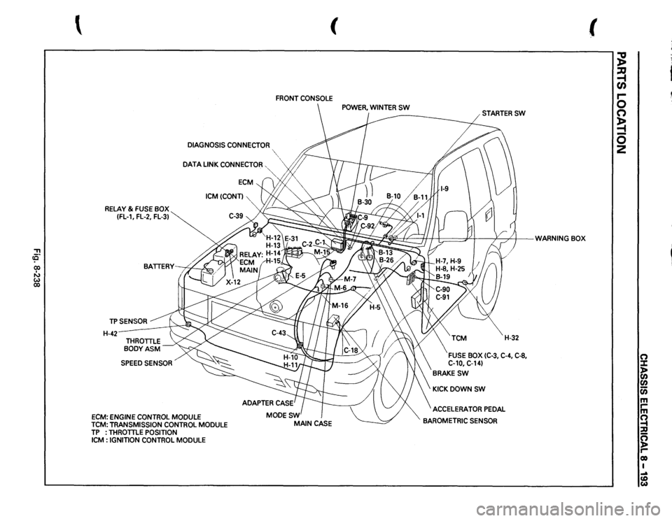
ECM:
ENGINE
CONTROL
MODULE
ICM(CONT)
TCM:
TRANSMISSION
CONTROL
MODULE
TP
: THROTTLE
POSITION
ICM
: IGNITION
CONTROL
MODULE
~;
t I:;::==PI
v
/)
WARNING
BOX
' .
!I
/;;'
H-32
FUSE
BOX
(C-3,
C-4, C-8,
C-10,
C-14)
BRAKESW
KICKDOWNSW ACCELERATOR
PEDAL
BAROMETRIC
SENSOR
(
;g ~ en r-0 (") ~ 0 2
0 :::1: )> (I) (I) c;; m rm ~ :;Q ~ co I .... (D w
Page 1390 of 1928
8 -200 CHASSIS ELECTRIC'Al
A/T SHIFT LOCK
GENERAL DESCRIPTION
This circuit consists of the starter switch, stoplight switch (vehicle w/o cruise control), brake switch (vehicle
w/cruise control),
shift lock controller, stoplight, backup light and mode switch.
The shift lock system is designed not
to allow the shift lever to be shifted from the "P" position to any other
position
without depressing the brake pedal while the starter switch is turned on.
The solenoid pin at the
lower portion of the shift lever retracts when the brake pedal is not depressed, thus
causing the shift lever cam
to be locked by the link lever.
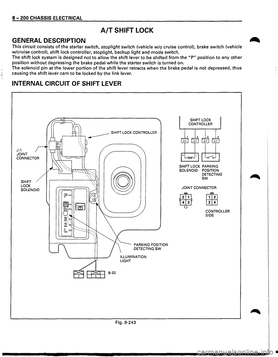
INTERNAL CIRCUIT OF SHIFT LEVER
J-1 JOINT CONNECTOR
SHIFT
LOCK
SOLENOID
B-32
PARKING POSITION
DETECTING SW
ILLUMINATION LIGHT
Fig. 8-243
SHIFT LOCK PARKING
SOLENOID POSITION
DETECTING
sw
JOINT CONNECTOR
CONTROLLER
SIDE
•
Page 1391 of 1928

"T1 ce· 00 I N ~ ~
(
BRAKE
SW
(W/CRUISE
CONTROL)
STOPLIGHT
SW
(W/0
CRUISE CONTROL)
SHIFT
LEVER
" ""'
SHIFT
LOCK
CONTROLLER
""''
RELAY
& FUSE
BOX
(FL-1,
FL-2)
(
STARTERSW
BRAKE
PEDAL
STOP
LIGHT
(LH)
\R-7 "-TRAILER
HARNESS
CONNECTOR
(H-44)
(
;g ~ r-0 0 ~ 5 z
0 :J: ~ en u; m rm ~ :a g reo I N 0 ....
Page 1394 of 1928
·;.
8 -204 CHASSIS ELECTRICAL
STARTER SWITCH
Refer to "START AND CHARGING" in this section.
STOPLIGHT
STOPLIGHT SWITCH
BRAKE SWITCH
Refer to "STOPLIGHT AND REAR DEFOGGER" in
,c, this section.
SHIFT LOCK CONTROLLER
Refer to the shift lock controller in Section 7 A
"AUTOMATIC TRANSMISSION."
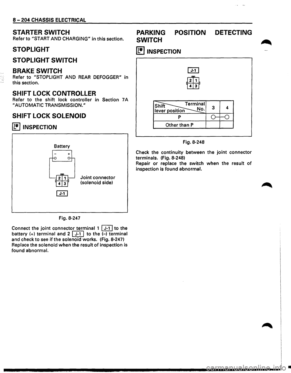
SHIFT LOCK SOLENOID
~ INSPECTION
Fig. 8-247
Joint connector
(solenoid side)
Connect the
joint connector terminal 1 ~to the
battery
(+) terminal and 2 [ill to the (-) terminal
and check to
see if the solenoid works. (Fig. 8-247)
Replace the solenoid when the result
of inspection is
found abnormal.
PARKING POSITION DETECTING
SWITCH
~
(1!]1NSPECTION
l2Ti1
Lill1
Other than P
Fig. 8-248
Check the continuity between the
joint connector
terminals. (Fig. 8-248)
Repair
or replace the switch when the result of
inspection is found abnormal.
I
I I
.............. ~ ................................ -----------------1 .
Page 1478 of 1928
8-288 CHASSIS ELECTRICAL
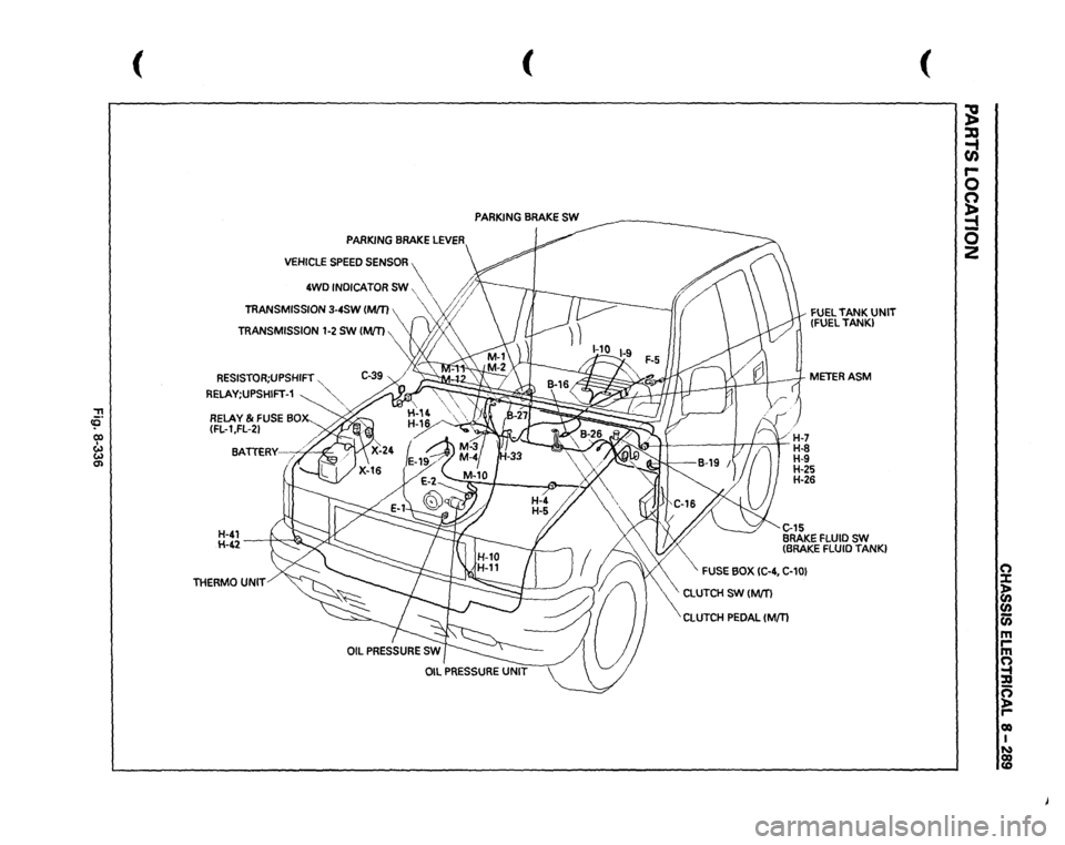
METER AND WARNING/INDICATOR LIGHT
GENERAL DESCRIPTION
The circuit consists of the starter switch, meter assembly, vehicle speed sensor, clutch switch, transmission
switch, lighting switch,
turn signal switch, thermo unit, oil pressure unit, Engine Control Module, fuel tank unit,
4WD
SW, oil pressure switch, parking brake switch, brake fluid switch, seat belt switch and illumination
controller.
The meter ASM contains the speedometer, tachometer, voltmeter, engine coolant temperature gauge, oil
pressure gauge, fuel gauge and warning/indicator lights.
The meter warning/indicator lights and
their bulb sockets are a unit, they are installed from the back of the
speedometer assembly.
Page 1479 of 1928
::!!
(
(
PARKING
BRAKE
SW
PARKING
BRAKE
LEVER
VEHICLE
SPEED
SENSOR
4WD
INDICATOR
SW,
~
' '
/;~>
TRANSMISSION
3-4SW
IMJT)
"vf;/
RESISTOR;UPSHIFT
."
RELAY;UPSHIFT-1
~":'""
RELAY
& FUSE
BOX-_
(FL-1
,FL-21 BA.
TTERY--.;:;4"~
H-41 H-42
-----;1-"'.,.,-~
THERMO
UNIT
FUEL
TANK
UNIT
(FUEL
TANK)
METERASM
~
16)
1 /
1
(
H-7
/'1'-J
? I n
H-8 H-9 H-25
H-26 C..15 BRAKE
FLUID
SW
(BRAKE
FLUID
TANK}
FUSE
BOX
IC-4,
C-10}
\CLUTCH
SW
(M/T)
CLUTCH
PEDAL
(Mm
(
~ ::xs ~ r-0 0 ~ -0 2
(") :X: ~ en (i) m rm (") ~ g roo I ~
Page 1485 of 1928
CHASSIS ELECTRICAL 8-295
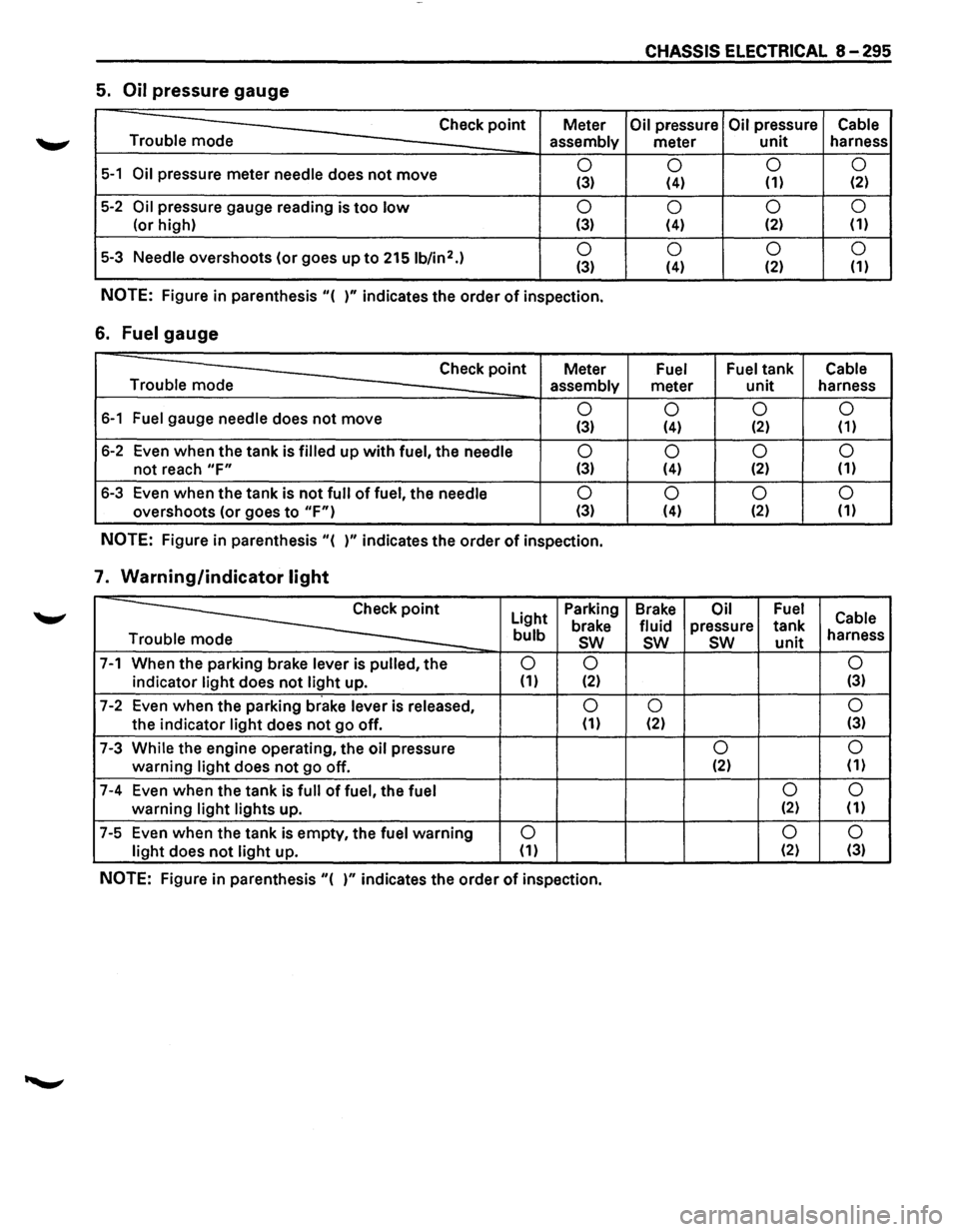
5. Oil pressure gauge
Check point Meter Oil pressure Oil pressure Cable
Trouble mode
assembly meter unit harness
5-1 Oil pressure meter needle does not move 0
0 0
0 (3) (4) (1) (2)
5-2 Oil pressure
gauge reading is too low 0
0 0
0
(or
high) (3) (4) (2) (1)
5-3 Needle overshoots
(or goes up to 2151b/in2.) 0
0 0 0 (3) (4) (2)
(1)
NOTE: Figure
in parenthesis "( )" indicates the order of inspection.
6. Fuel gauge
Check point Meter Fuel Fuel tank Cable
Trouble mode assembly
meter unit harness
6-1 Fuel gauge needle does not move 0
0 0 0 (3) (4) (2) (1)
6-2 Even when the tank is filled up with fuel, the needle 0
0 0
0
not reach "F" (3) (4) (2)
(1)
6-3
Even when the tank is not full of fuel, the needle 0
0 0
0
overshoots (or goes to "F") (3) (4) (2) (1)
NOTE: Figure
in parenthesis "( )" indicates the order of inspection.
7. Warning/indicator light
~
Light Parking
Brake Oil Fuel Cable brake fluid pressure tank bulb sw sw sw unit harness
e
7-1 When the parking brake lever is pulled, the 0 0 0
indicator light does not light up. (1) (2) (3)
7-2 Even
when the parking brake lever is released, 0 0 0
the indicator light does not go off. (1) (2) (3)
7-3 While the engine operating,
the oil pressure 0 0
warning light does not go
off. (2)
(1)
7-4 Even
when the tank is full of fuel, the fuel 0 0
warning light lights
up. (2) (1)
7-5 Even
when the tank is empty, the fuel warning 0 0
0
light does not light up. (1) (2)
(3)
NOTE: Figure in parenthesis "( )" indicates the order of inspection.
Page 1501 of 1928
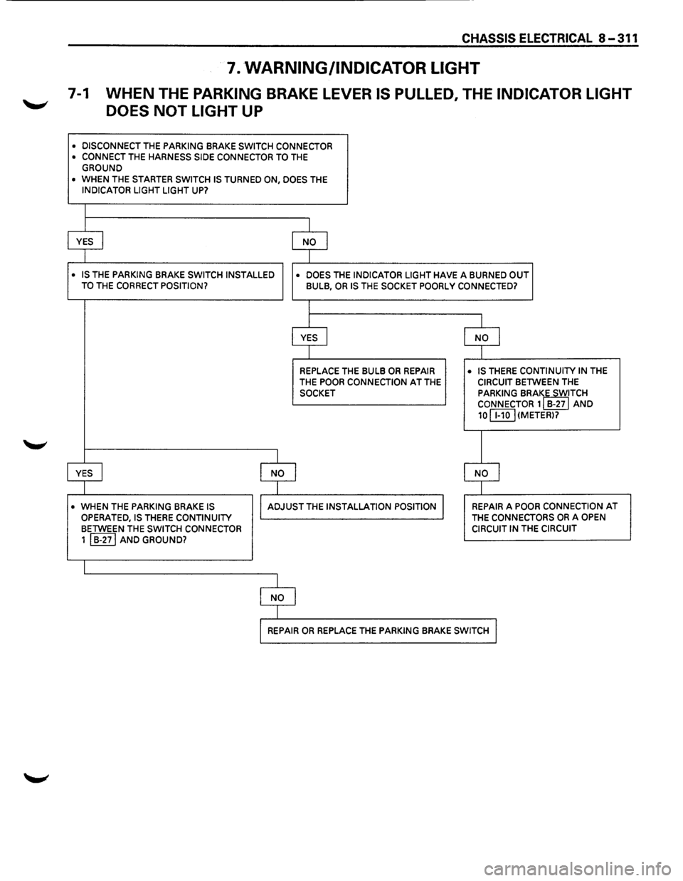
CHASSIS ELECTRICAL 8-311
7. WARNING/INDICATOR LIGHT
7-1 WHEN THE PARKING BRAKE LEVER IS PULLED, THE INDICATOR LIGHT
DOES
NOT LIGHT UP
• DISCONNECT THE PARKING BRAKE SWITCH CONNECTOR • CONNECT THE HARNESS SIDE CONNECTOR TO THE GROUND
• WHEN THE STARTER SWITCH IS TURNED ON, DOES THE INDICATOR LIGHT LIGHT UP?
I
YES I NO I
I
• IS THE PARKING BRAKE SWITCH INSTALLED
• DOES THE INDICATOR LIGHT HAVE A BURNED OUT TO THE CORRECT POSITION? BULB, OR IS THE SOCKET POORLY CONNECTED?
I
I
YES I NO j
I
REPLACE THE BULB OR REPAIR • IS THERE CONTINUITY IN THE
THE POOR CONNECTION AT THE CIRCUIT BETWEEN THE
SOCKET PARKING BRAIE SWITCH CONNECTOR 1 B-27 AND
10 C8.QJ (METER)?
I
YES I I NO I NO I
I
• WHEN THE PARKING BRAKE IS I ADJUST THE INSTALLATION POSITION I REPAIR A POOR CONNECTION AT
OPERATED, IS THERE CONTINUITY THE CONNECTORS OR A OPEN
BETWEEN THE SWITCH CONNECTOR CIRCUIT IN THE CIRCUIT
1 I B-271 AND GROUND?
I
I NO I
I
I REPAIR OR REPLACE THE PARKING BRAKE SWITCH I