transmission ISUZU TROOPER 1995 Workshop Manual
[x] Cancel search | Manufacturer: ISUZU, Model Year: 1995, Model line: TROOPER, Model: ISUZU TROOPER 1995Pages: 1928
Page 1100 of 1928
78-10 MANUAL TRANSMISSION
GEAR CONTROL BOX ASSEMBLY
l••l REMOVAL
Preparation:
• Disconnect battery negative (-) cable.
1. Knob
• Remove knobs of the transmission control
lever
and transfer control lever.
2. Front console assembly
• Remove front console assembly.
•
Disconnect harness connector.
• Remove rear heater duct.
3. Grommet assembly
• Remove grommet assembly.
4. Transmission control lever and transfer control
lever
• Remove transmission control lever and
transfer
control lever.
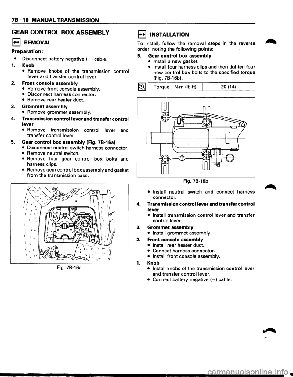
5. Gear control box assembly (Fig. 7B-16a)
• Disconnect neutral switch harness connector.
• Remove neutral switch.
• Remove four gear control box bolts and
harness
clips.
•
Remove gear control box assembly and gasket
from the transmission case.
Fig. 7B-16a
l••l INSTALLATION
To install, follow the removal steps in the reverse
order, noting the
following points:
5. Gear control box assembly
• Install a new gasket.
• Install four harness clips and then tighten four
new control box bolts to the specified torque
(Fig. 7B-16b).
1~1 Torque N·m (lb·ft) 20 (14)
Fig. 7B-16b
• Install neutral switch and connect harness
connector.
4.
Transmission control lever and transfer control
lever
• Install transmission control lever and transfer
control lever.
3. Grommet assembly
• Install grommet assembly.
2. Front console assembly
• Install rear heater duct.
• Conne,ct harness connector.
• Install front console assembly.
1. Knob
• Install knobs of the transmission control lever
and transfer control lever.
• Conne·ct
battery negative (-) cable.
•
Page 1101 of 1928

MANUAL TRANSMISSION 78-11
MEMO
··-----------·-··----------------------------------------\
-----------------------------------------·····-----------\
--------------···----------------------------·····\
·······
----····---------·---------------------------------------\
------------------------------------------------------------------·---------\
-----------------------------········
-------------------------------------------------------------------------------------------------------------------------------------------\
--------------------·······----
····--------------------------------------------------------\
--------···
-·-···---------------------------------------------·------\
-------------·--·---------------·------
---···-----------······-------------------·\
················--------\
----··--·----------------------------------------------------·\
·-------------········--------------------
-----------------·-······------------------------·\
···-------------------------···---------------------·-·---------------------------------------------------------\
·---
Page 1102 of 1928
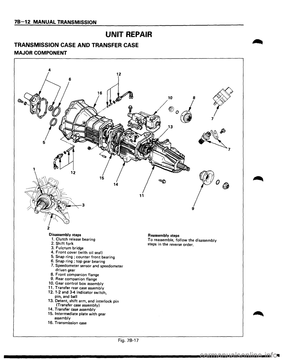
78-12 MANUAL TRANSMISSION
UNIT REPAIR
TRANSMISSION CASE AND TRANSFER CASE
MAJOR COMPONENT
4
11
2
Disassembly steps Reassembly steps 7
~
9
1. Clutch release
bearing 2. Shift fork
3. Fulcrum bridge To reassemble, follow the disassembly
steps in the reverse order.
4.
Front cover (with oil seal)
5. Snap ring ; counter front bearing
6. Snap ring ; top gear bearing
7. Speedometer sensor and speedometer
driven gear
8. Front companion flange
9. Rear companion flange
10. Gear control box assembly
11. Transfer rear case assembly
12.
1·2 and 3-4 indicator switch,
pin, and ball 13. Detent, shift arm, and interlock pin
(Transfer case assembly) 14. Transfer case assembly
15. Intermediate plate with gear
assembly
16. Transmission case
Fig. 78-17
7
Ill
Page 1103 of 1928
1•!,.1 DISASSEMBLY
Preparation:
• Clean the exterior of the unit with solvent.
•
Remove the drain plug from the transmission
case and transfer case and drain the
lubricant.
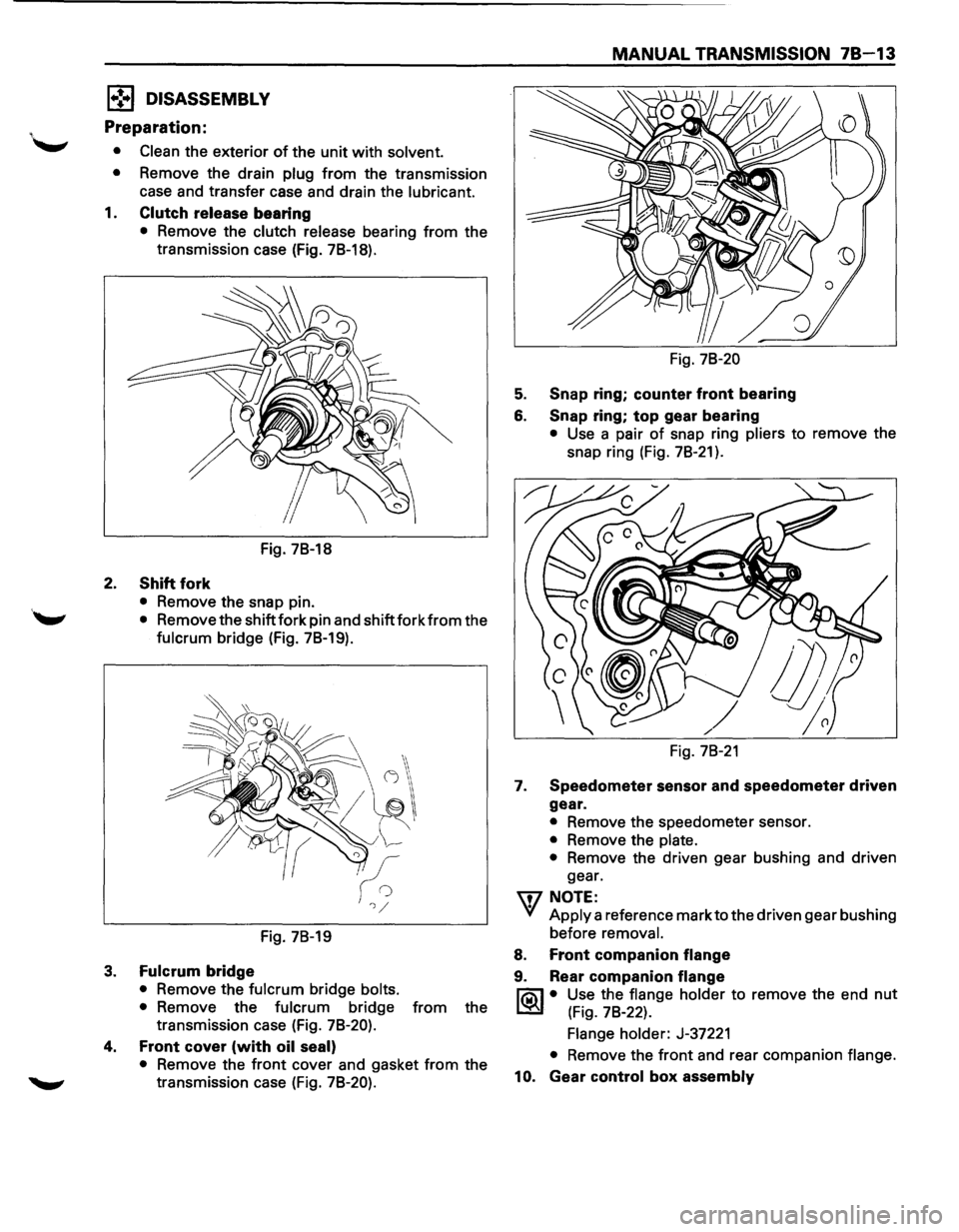
1. Clutch release bearing
• Remove the clutch release bearing from the
transmission case (Fig.
78-18).
Fig. 78-18
2. Shift fork
• Remove the snap pin.
''-" • Remove the shift fork pin and shift fork from the
fulcrum bridge (Fig. 78-19).
Fig. 78-19
3. Fulcrum bridge
• Remove the fulcrum bridge bolts.
•
Remove the fulcrum bridge from the
transmission case (Fig.
78-20).
4. Front cover (with oil seal)
• Remove the front cover and gasket from the
transmission case (Fig.
78-20).
MANUAL TRANSMISSION 78-13
Fig. 78-20
5. Snap ring; counter front bearing
6. Snap ring; top gear bearing
• Use a pair of snap ring pliers to remove the
snap ring (Fig.
78-21 ).
Fig. 78-21
1. Speedometer sensor and speedometer driven
gear.
• Remove the speedometer sensor.
• Remove the plate.
•
Remove the driven gear bushing and driven
gear.
'\fl NOTE:
VI Apply a reference mark to the driven gear bushing
before
removal.
8. Front companion flange
9. Rear companion flange
l'ia\1 • Use the flange holder to remove the end nut
~ (Fig. 78-22).
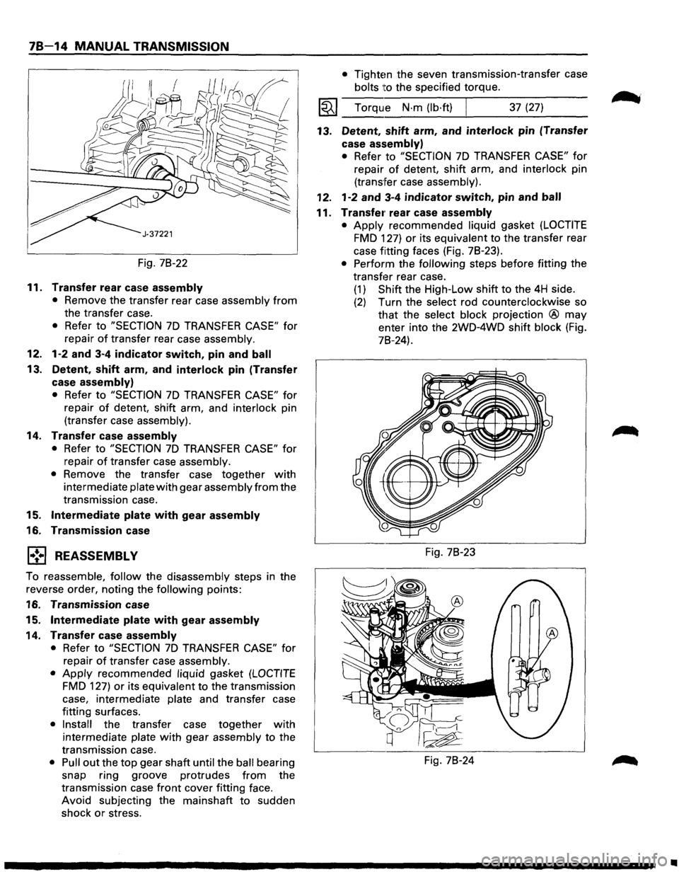
Flange holder: J-37221
• Remove the front and rear companion flange.
10. Gear control box assembly
Page 1104 of 1928
78-14 MANUAL TRANSMISSION
Fig. 78-22
11. Transfer rear case assembly
• Remove the transfer rear case assembly from
the transfer case.
• Refer to "SECTION 7D TRANSFER CASE" for
repair
of transfer rear case assembly.
12. 1-2 and 3-4 indicator switch, pin and ball
13. Detent, shift arm, and interlock pin (Transfer
case
assembly)
• Refer to "SECTION 7D TRANSFER CASE" for
repair of detent, shift arm, and interlock pin
(transfer case assembly).
14. Transfer case assembly
• Refer to "SECTION 7D TRANSFER CASE" for
repair
of transfer case assembly.
• Remove the transfer case together with
intermediate plate with gear assembly from the
transmission case.
15. Intermediate plate with gear assembly
16. Transmission case
l•!•l REASSEMBLY
To reassemble, follow the disassembly steps in the
reverse order, noting the following points:
16. Transmission case
15.
Intermediate plate with gear assembly
14. Transfer case assembly
• Refer to "SECTION 7D TRANSFER CASE" for
repair
of transfer case assembly.
• Apply recommended liquid gasket (LOCTITE
FMD 127) or its equivalent to the transmission
case, intermediate plate and transfer case
fitting surfaces.
• Install the transfer case together with
intermediate plate with gear assembly to the
transmission case.
• Pull out the top gear shaft until the ball bearing
snap ring groove protrudes
from the
transmission case
front cover fitting face.
Avoid subjecting the mainshaft
to sudden
shock
or stress.
• Tightem the seven transmission-transfer case
bolts
ito the specified torque.
I~I __ T_o_rq~u __ e __ N_·_m_(~lb_·f~t)~ ______ 3_7_(2_7~) ____ _
13. Detent, shift arm, and interlock pin (Transfer
case
assembly)
• Refer to "SECTION 7D TRANSFER CASE" for
repair of detent, shift arm, and interlock pin
(transfer case assembly).
12. 1-2 and 3-4 indicator switch, pin and ball
11. Transfe1· rear case assembly
• Apply recommended liquid gasket (LOCTITE
FMD 127) or its equivalent to the transfer rear
case fitting faces (Fig. 78-23).
• Perform the following steps before fitting the
transf13r rear case.
(1) Shift the High-Low shift to the 4H side.
(2) Turn the select rod counterclockwise so
that the select block projection ® may
enter into the 2WD-4WD shift block (Fig.
78-24).
Fig. 78-23
Fig. 78-24
•
Page 1105 of 1928
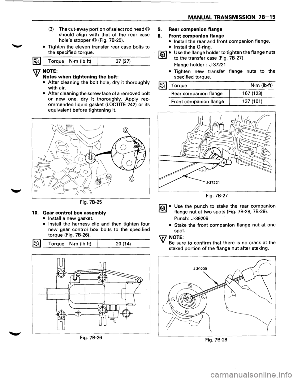
(3) The cut-away portion of select rod head@
should
align with that of the rear case
hole's
stopper© (Fig. 78-25).
• Tighten the eleven transfer rear case bolts to
the specified torque.
1~1 Torque N·m (lb·ft) j 37 (27)
U7NOTE:
'({ Notes when tightening the bolt:
10.
• After cleaning the bolt hole, dry it thoroughly
with air.
• After cleaning the screw face of a removed bolt
or new one, dry it thoroughly. Apply rec
ommended liquid gasket (LOCTITE 242) or its
equivalent before tightening it.
Fig.
78-25
Gear control box assembly
• Install a new gasket.
• Install the harness clip and then tighten four
new gear control
box bolts to the specified
torque (Fig.
78-26).
I~I_T_o_rq_u_e_N_·m_(lb_·_ft)____.l ___ 20_(_1_4) __ _
Fig. 78-26
MANUAL TRANSMISSION 78-15
9. Rear companion flange
8. Front companion flange
• Install the rear and front companion flange.
• Install the 0-ring.
IQil • Use the flange holder to tighten the flange nuts
l..::rJ to the transfer case (Fig. 78-27).
Flange holder : J-37221
• Tighten new transfer flange nuts to the
specified torque.
I~I_T_o_r-..:.q_ue ______ -. ___ N_·_m_(lb_·_ft_)
Rear companion flange 167 (123)
Front companion flange 137 (1 01)
Fig. 78-27
1®.1• Use the punch to stake the rear companion
flange
nut at two spots (Fig. 78-28, 78-29).
Punch: J-39209
• Stake the front companion flange nut at one
spot.
U7 NOTE:
'({ Be sure to confirm that there is no crack at the
staked portion
of the flange nut after staking.
Fig.
78-28
Page 1106 of 1928
78-16 MANUAL TRANSMISSION
7.
mm{in)
MAX. 1.5 (0.06)
MAX. 1.5 10.06)
MIN. 4 (0.16)
MIN. 4 (0.16)
Fig. 78-29
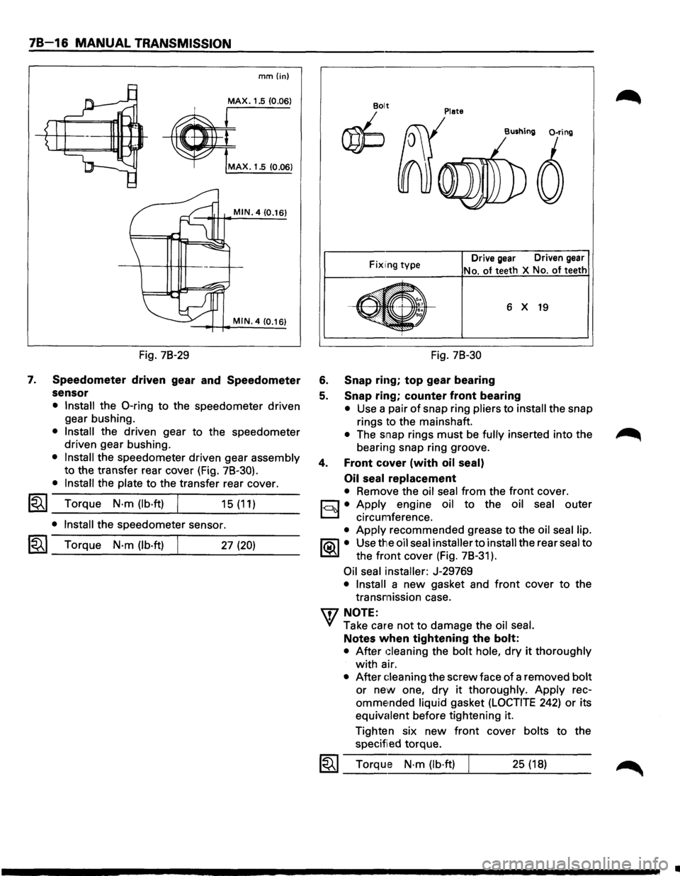
Speedometer driven gear and Speedometer
sensor
• Install the 0-ring to the speedometer driven
gear bushing.
• Install the driven gear to the speedometer
driven gear bushing.
• Install the speedometer driven gear assembly
to the transfer rear cover (Fig. 78-30).
• Install the plate to the transfer rear cover.
l"i't I Torque N·m (lb·ft) ~ _...:.____---~... ___ _ 15 (11)
• Install the speedometer sensor.
I~I_T_o_rq...;_u_e_N_·_m_(_lb_·ft_l----~. ___ 2_7_(2_0_) __ _
Plate Bolt
~
Fix1ing type Drive gear Driven gear
No. of teeth
X No. of teeth
6 X 19
Fig. 78-30
6. Snap ring; top gear bearing
5. Snap ring; counter front bearing
• Use a pair of snap ring pliers to install the snap
rings to the mainshaft.
• The snap rings must be fully inserted into the
bearing snap ring groove.
4. Front cover (with oil seal)
Oil seal
replacement
• Remove the oil seal from the front cover.
c:::;J • Apply engine oil to the oil seal outer
D circumference.
• Apply recommended grease to the oil seal lip.
1®.1• Use the oil seal installer to install the rear seal to
the
front cover (Fig. 78-31 ).
Oil seal installer: J-29769
• Install a new gasket and front cover to the
transmission case.
'\f7 NOTE:
"+({ Take care not to damage the oil seal.
Notes when tightening the bolt:
• After Gleaning the bolt hole, dry it thoroughly
with air.
• After Gleaning the screw face of a removed bolt
or new one, dry it thoroughly. Apply rec
omme~nded liquid gasket (LOCTITE 242) or its
equivalent before tightening it.
Tighten six
new front cover bolts to the
specified torque.
1~1 Torque N·m (lb·ft) 25 (18)
..
Page 1107 of 1928
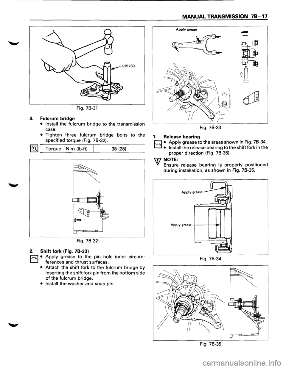
Fig. 78-31
3. Fulcrum bridge
• Install the fulcrum bridge to the transmission
case.
• Tighten three fulcrum bridge bolts to the
specified torque (Fig. 78-32).
~~~ Torque N·m (lb·ft) J 38 (28)
Fig. 78-32
2. Shift fork (Fig. 78-33)
c:::;:]. • Apply grease to the pin hole inner circum
D ferences and thrust surfaces.
• Attach the shift fork to the fulcrum bridge by
inserting the shift fork pin
from the bottom side
of the fulcrum bridge.
• Install the washer and snap pin.
MANUAL TRANSMISSION 78-17
Apply grease
Fig. 78-33
1. Release bearing
c:::;:] • Apply grease to the areas shown in Fig. 78-34.
D • Install the release bearing to the shift fork in the
proper direction (Fig. 78-35).
\f7 NOTE:
'V Ensure release bearing is properly positioned
during
installation, as shown in Fig. 78-35.
Apply grease
Apply grease +---+--11~
Fig. 78-34
Fig. 78-35
Page 1108 of 1928
78-18 MANUAL TRANSMISSION
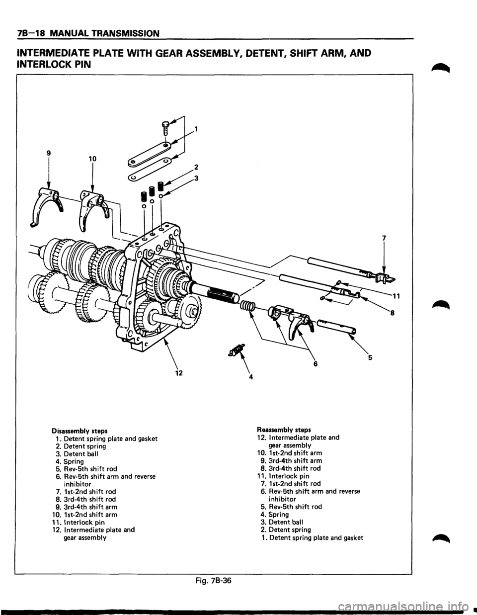
INTERMEDIATE PLATE WITH GEAR ASSEMBLY, DETENT, SHIFT ARM, AND
INTERLOCK PIN
9 10
Disassembly steps
1. Detent spring plate and gasket
2. Detent spring
3. Detent ball
4. Spring 5. Rev-5th shift rod
6. Rev-5th shift arm and reverse
inhibitor
7. 1st-2nd shift rod
8. 3rd-4th shift rod
9. 3rd-4th shift arm
10. 1st-2nd shift arm
11. Interlock pin
12. Intermediate plate and
gear assembly
12
1
~ 4
Fig. 78-36
Reassembly steps
12.
Intermediate plate and
gear assembly
10. 1st-2nd shift arm
9. 3rd-4th shift arm
8. 3rd-4th shift rod
11.
Interlock pin 7. 1st-2nd shift rod 6. Rev-5th shift arm and reverse
i11hibitor 5. Rev-5th shift rod
4. Spring 3. Detent ball 2. Detent spring
1. Detent spring plate and gasket
7
1
•
Page 1109 of 1928
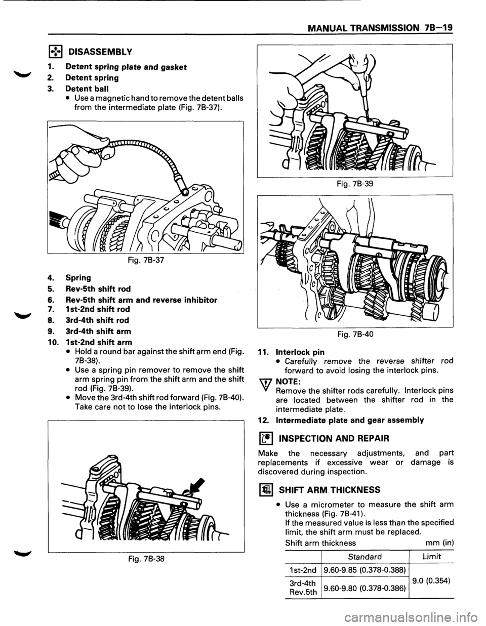
1 .. !•1 DISASSEMBL V
1. Detent spring plate and gasket
2. Detent spring
3. Detent ball
• Use a magnetic hand to remove the detent balls
from the intermediate plate (Fig. 78-37).
Fig. 78-37
4. Spring
5. Rev-5th shift rod
6. Rev-5th shift arm and reverse inhibitor
7. 1st-2nd shift rod
8. 3rd-4th shift rod
9. 3rd-4th shift arm
10. 1st-2nd shift arm
• Hold a round bar against the shift arm end (Fig.
78-38).
• Use a spring pin remover to remove the shift
arm spring pin
from the shift arm and the shift
rod (Fig. 78-39).
• Move the 3rd-4th shift rod forward (Fig. 78-40).
Take care not to lose the interlock pins.
Fig. 78-38
MANUAL TRANSMISSION 78-19
Fig. 78-39
Fig. 78-40
11. Interlock pin
• Carefully remove the reverse shifter rod
forward to avoid
losing the interlock pins.
U7 NOTE:
'YI Remove the shifter rods carefully. Interlock pins
are
located between the shifter rod in the
intermediate
plate.
12. Intermediate plate and gear assembly
[1:!) INSPECTION AND REPAIR
Make the necessary adjustments, and part
replacements
if excessive wear or damage is
discovered during inspection.
~ SHIFT ARM THICKNESS
• Use a micrometer to measure the shift arm
thickness (Fig. 78-41).
If the measured value is less than the specified
limit, the shift arm must be replaced.
Shift
arm thickness mm (in)
Standard Limit
1st-2nd 9.60-9.85
(0.378-0.388)
3rd-4th 9.0
(0.354)
Rev.5th 9.60-9.80 (0.378-0.386)