transmission ISUZU TROOPER 1995 Workshop Manual
[x] Cancel search | Manufacturer: ISUZU, Model Year: 1995, Model line: TROOPER, Model: ISUZU TROOPER 1995Pages: 1928
Page 1110 of 1928
78-20 MANUAL TRANSMISSION
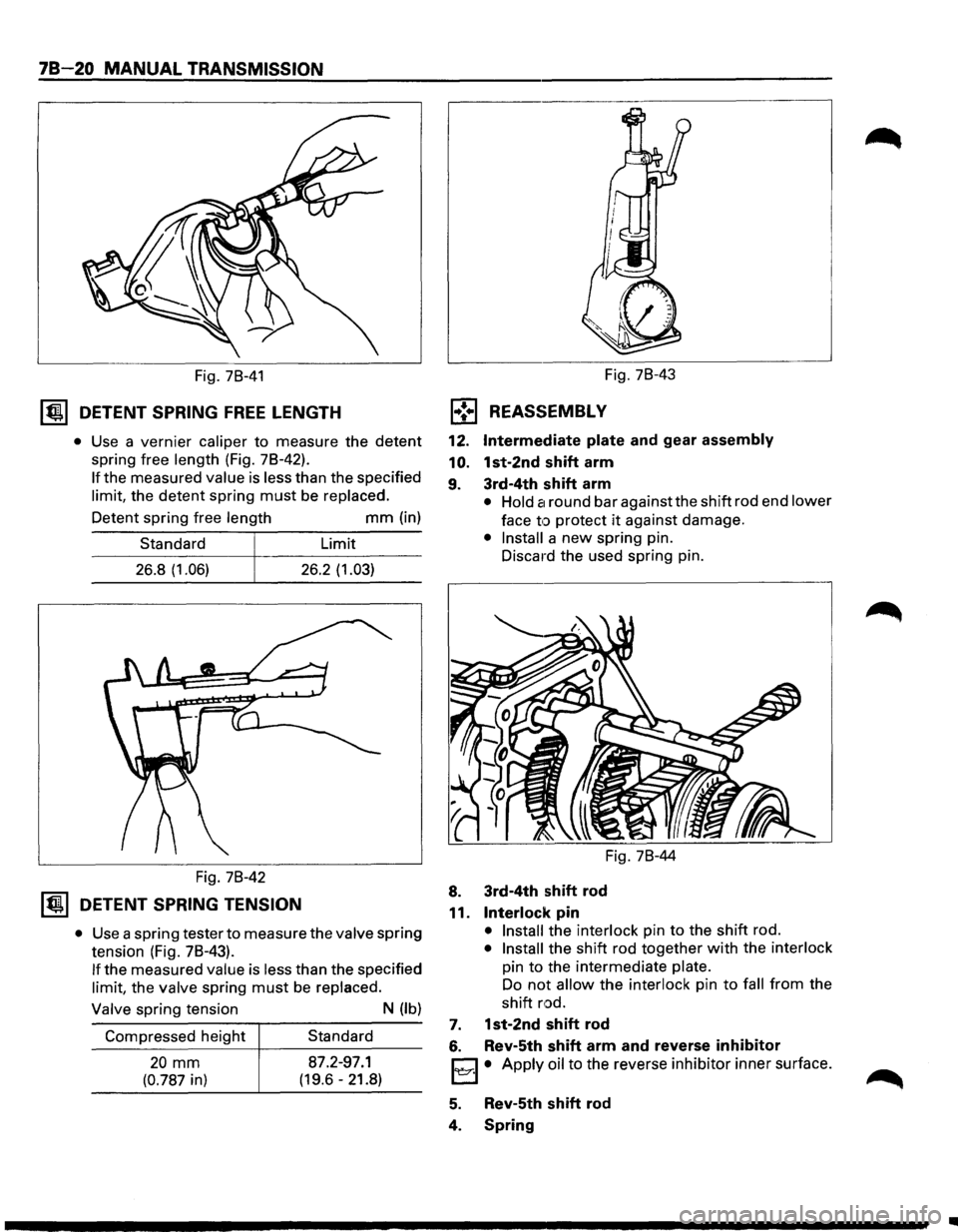
Fig. 78-41
~ DETENT SPRING FREE LENGTH
• Use a vernier caliper to measure the detent
spring free length (Fig. 78-42).
If the measured value is less than the specified
limit, the
detent spring must be replaced.
Detent spring free length
mm (in)
Standard Limit
26.8 (1.06) 26.2 (1.03)
Fig. 78-42
~ DETENT SPRING TENSION
• Use a spring tester to measure the valve spring
tension (Fig. 78-43).
If the measured value is less than the specified
limit, the valve spring must be replaced.
Valve spring tension
N (lb)
Compressed height Standard
20 mm 87.2-97.1
(0.787 in) (19.6-21.8) Fig.
78-43
l•!•l REASSEMBLY
12. Intermediate plate and gear assembly
10.
1st-2nd shift arm
9. 3rd-4th shift arm
• Hold Cl round bar against the shift rod end lower
face to protect it against damage.
• Install a new spring pin.
Discard the used spring pin.
Fig. 78-44
8. 3rd-4th shift rod
11. Interlock pin
• Install the interlock pin to the shift rod.
• Install the shift rod together with the interlock
pin
to the intermediate plate.
Do
not allow the interlock pin to fall from the
shift
rod.
7. 1st-2nd shift rod
6. Rev-5th shift arm and reverse inhibitor
EJ • Apply oil to the reverse inhibitor inner surface.
5. Rev-5th shift rod
4. Spring
..
Page 1111 of 1928
3. Detent ball
E§3 • Apply grease to the detent balls.
2. Detent spring
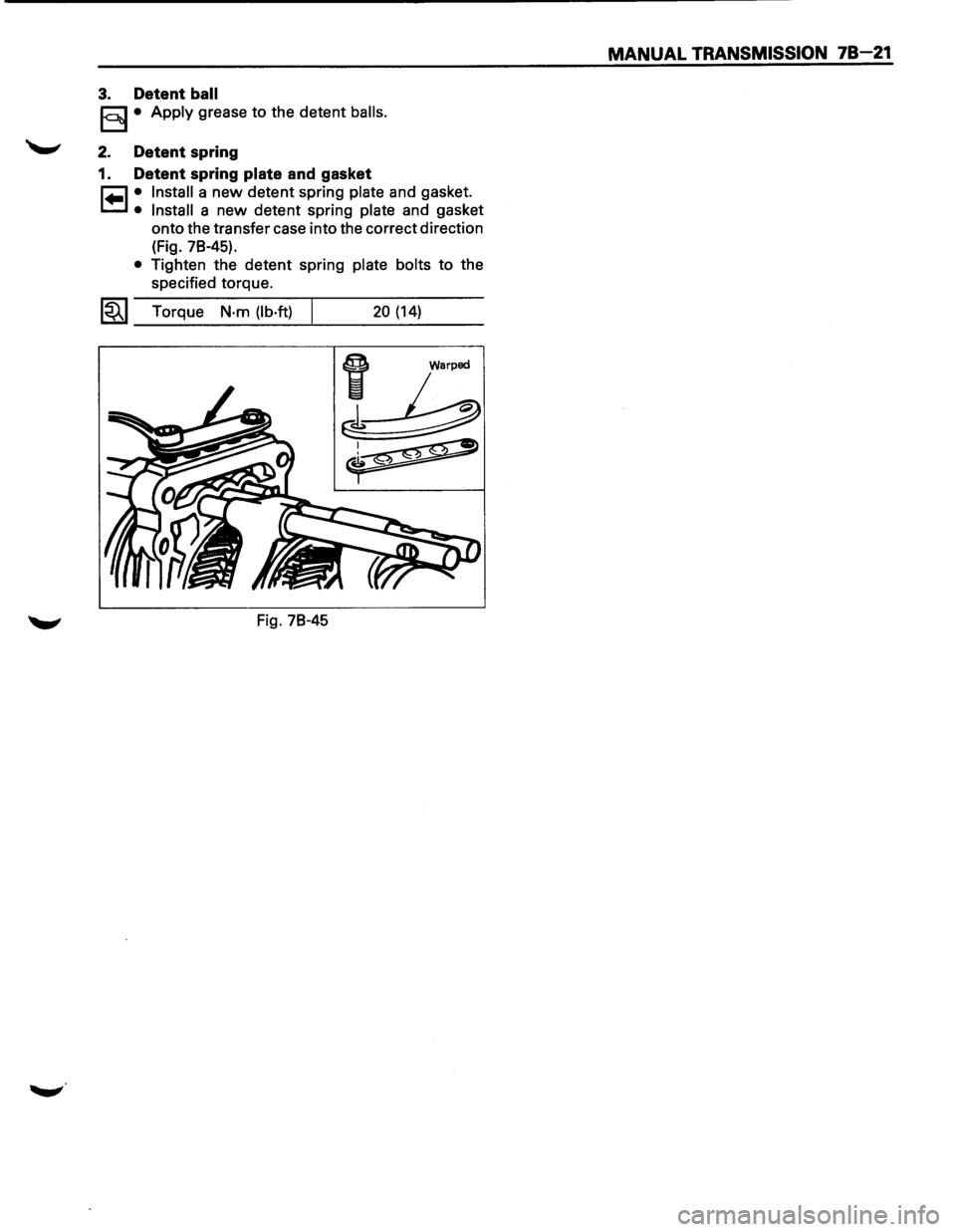
1. Detent spring
plate and gasket
r=l • Install a new detent spring plate and gasket.
t=.l • Install a new detent spring plate and gasket
onto the transfer case into the correct direction
(Fig. 78-45).
• Tighten the detent spring plate bolts to the
specified torque.
1~1 Torque N·m (lb·ft) I 20 (14)
Fig. 78-45
MANUAL TRANSMISSION 78-21
Page 1112 of 1928
78-22 MANUAL TRANSMISSION
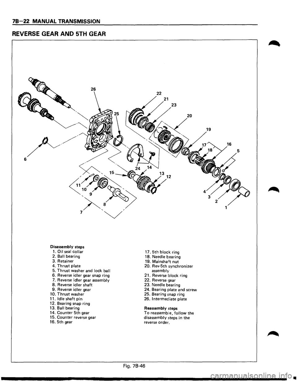
REVERSE GEAR AND 5TH GEAR
6
26 22
23
20
-~~ 19
-~;(>~-~~·
<:/'-. ~~2~
)<., ""-, 15~ 13
7 ~
Disassembly steps
1.
Oil seal collar 2. Ball bearing
3. Retainer
4.
Thrust plate
5. Thrust washer and lock ball 6. Reverse idler gear snap ring 7. Reverse idler gear assembly 8. Reverse idler shaft 9. Reverse idler gear 10. Thrust washer
11. Idle shaft pin
12. Bearing snap ring
13. Ball bearing
14. Counter 5th gear
15. Counter reverse gear
16. 5th gear 17.
5th block ring
18. Needle bearing
19.
Mainshai't nut 20. Rev-5th synchronizer assembly
21. Reverse block ring 22. Reverse !~ear 23. Needle bearing
24. Bearing plate and screw
25. Bearing snap ring
26. Intermediate plate
Reassembly !lteps To reassemble, follow the disassembly !iteps in the reverse order.
Fig. 78-46
5
..
Page 1113 of 1928
l•!•l DISASSEMBLY
1. Oil Seal Collar
2. Ball bearing
3. Retainer
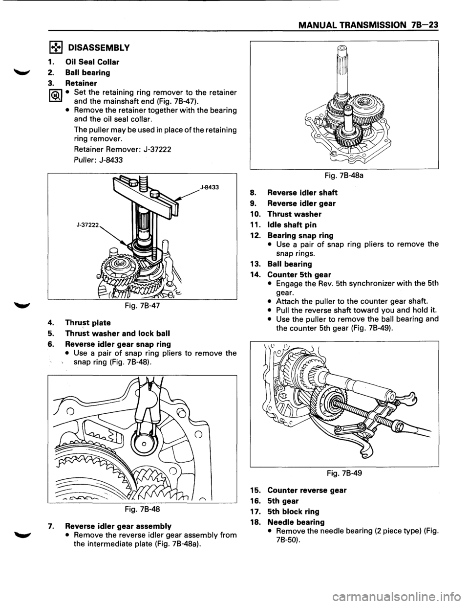
I®J • Set the retaining ring remover to the retainer
and the mainshaft end (Fig. 78-47).
• Remove the retainer together with the bearing
and the
oil seal collar.
The puller may be used in place ofthe retaining
ring remover.
Retainer Remover: J-37222
Puller: J-8433
Fig. 78-47
4. Thrust plate
5. Thrust washer and lock ball
6. Reverse idler gear snap ring
J-8433
• Use a pair of snap ring pliers to remove the
snap ring (Fig. 78-48).
Fig. 78-48
7. Reverse idler gear assembly
• Remove the reverse idler gear assembly from
the intermediate plate (Fig. 78-48a).
MANUAL TRANSMISSION 78 23
Fig. 78-48a
8. Reverse idler shaft
9. Reverse idler gear
1
0. Thrust washer
11.
Idle shaft pin
12. Bearing snap ring
• Use a pair of snap ring pliers to remove the
snap rings.
13. Ball bearing
14. Counter 5th gear
• Engage the Rev. 5th synchronizer with the 5th
gear.
• Attach the puller to the counter gear shaft.
• Pull the reverse shaft toward you and hold it.
• Use the puller to remove the ball bearing and
the counter 5th gear (Fig. 78-49).
Fig. 78-49
15. Counter reverse gear
16. 5th gear
17. 5th
block ring
18.
Needle bearing
• Remove the needle bearing (2 piece type) (Fig.
78-50).
Page 1114 of 1928
78-24 MANUAL TRANSMISSION
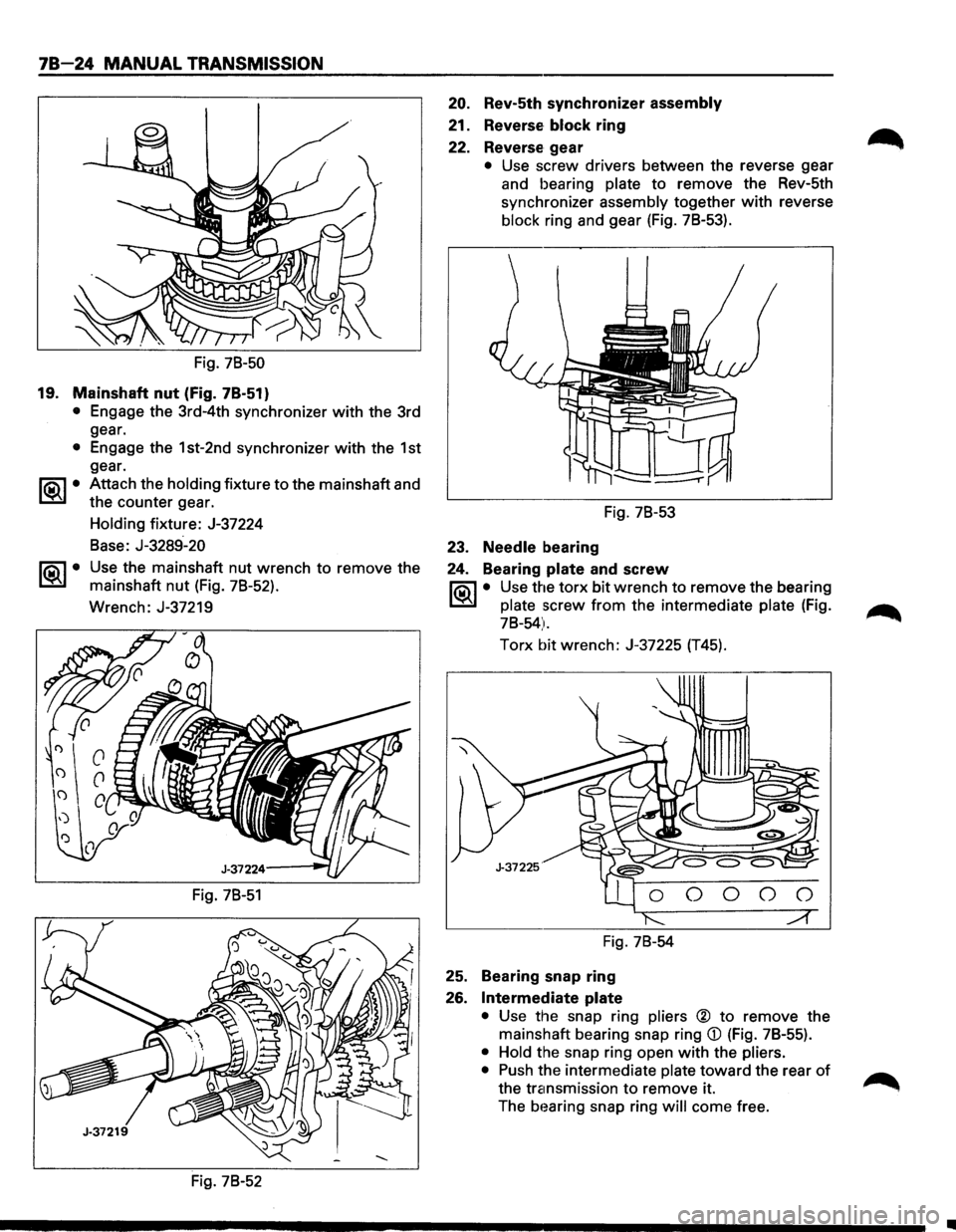
Fig. 78-50
19. Mainshaft nut (Fig. 7B-51)
• Engage the 3rd-4th synchronizer with the 3rd
gear.
• Engage the 1st-2nd synchronizer with the 1st
gear.
~~~· Attach the holding fixture to the mainshaft and
the counter gear.
~·
Holding fixture: J-37224
Base: J-3289-20
Use the mainshaft nut wrench to remove the
mainshaft
nut (Fig. 78-52).
Wrench: J-37219
Fig. 78-51
Fig. 78-52
20. Rev-5th synchronizer assembly
21. Reverse block ring
22. Reverse gear
• Use screw drivers between the reverse gear
and bearing plate to remove the Rev-5th
synchronizer assembly together
with reverse
block ring and gear (Fig. 78-53).
Fig. 78-53
23. Needle bearing
24. Bearing
plate and screw
1'?.3\1 • Use the torx bit wrench to remove the bearing
C::BJ plate screw from the intermediate plate (Fig.
78-54).
Torx bit wrench: J-37225 (T45).
Fig. 78-54
25. Bearing snap ring
26.
Intermediate plate
• Use the snap ring pliers ® to remove the
mainshaft bearing snap ring
CD (Fig. 7B-55).
• Hold the snap ring open with the pliers.
• Push the intermediate plate toward the rear of
the transmission to remove it.
The
b1~aring snap ring will come free.
•
Page 1115 of 1928
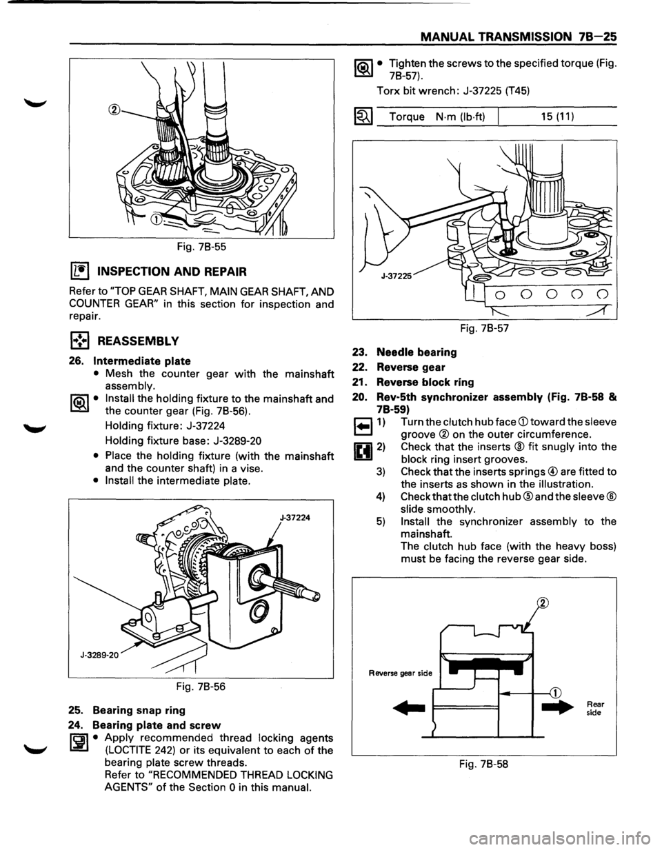
Fig. 78-55
IL•I INSPECTION AND REPAIR
Refer to "TOP GEAR SHAFT, MAIN GEAR SHAFT, AND
COUNTER GEAR" in this section for inspection and
repair.
l•!•l REASSEMBLY
26. Intermediate plate
• Mesh the counter gear with the mainshaft
assembly.
1®.1• Install the holding fixture to the mainshaft and
the counter gear (Fig. 78-56).
Holding fixture: J-37224
Holding fixture base:
J-3289-20
• Place
the holding fixture (with the mainshaft
and the counter shaft) in a vise.
• Install the intermediate plate.
Fig. 78-56
25. Bearing snap ring
24. Bearing
plate and screw
rci1 • Apply recommended thread locking agents
l.:i!.l (LOCTITE 242) or its equivalent to each of the
bearing
plate screw threads.
Refer to
"RECOMMENDED THREAD LOCKING
AGENTS"
of the Section 0 in this manual.
MANUAL TRANSMISSION 78-25
1®.1• Tighten the screws to the specified torque (Fig.
78-57).
Torx bit wrench: J-37225 (T45)
1~1 Torque N·m (lb·ft) I
23. Needle bearing
22. Reverse gear
Fig. 78-57
21. Reverse block ring
15 (11)
20. Rev-5th synchronizer assembly (Fig. 7B·58 &
7B·59)
r=l1) Turn the clutch hub face CD toward the sleeve
~ groove ® on the outer circumference.
0 2) Check that the inserts ® fit snugly into the
1!!.!1 block ring insert grooves.
3) Check that the inserts springs@ are fitted to
the inserts
as shown in the illustration.
4) Check thatthe clutch hub@ and the sleeve®
slide smoothly.
5) Install the synchronizer assembly to the
mainshaft.
The clutch hub face (with the heavy boss)
must be facing the reverse gear side.
Reverse gear side
... F====I
Fig. 78-58
Rear
side
Page 1116 of 1928
78-26 MANUAL TRANSMISSION
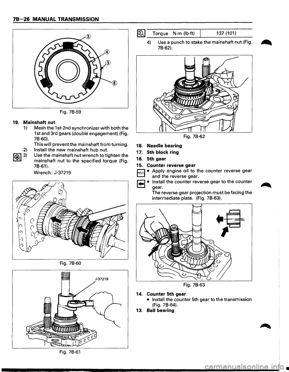
Fig. 78-59
19. Mainshaft nut
1) Mesh the 1st-2nd synchronizer with both the
1st and 3rd gears
(double engagement) (Fig.
78-60).
2)
~3)
This will prevent the mainshaft from turning.
Install the new mainshaft hub nut.
Use the mainshaft
nut wrench to tighten the
mainshaft
nut to the specified torque (Fig.
78-61).
Wrench: J-37219
Fig. 78-60
Fig. 78-61
1~1 Torque N·m (lb·ft) 137 (101)
4) Use a punch to stake the mainshaft nut (Fig. ~
78-62).
18. Needle bearing
17. 5th
block ring
16. 5th gear
Fig. 78-62
15. Counter reverse gear
Cl • Apply engine oil to the counter reverse gear
L.::::::.l and the reverse gear.
8 • Install the counter reverse gear to the counter
gear.
The reverse gear projection
must be facing the
intermediate
plate. (Fig. 78-63).
Fig. 78-63
14. Counte1· 5th gear
• Install the counter 5th gear to the transmission
(Fig. 78-64).
13. Ball bearing
•
Page 1117 of 1928
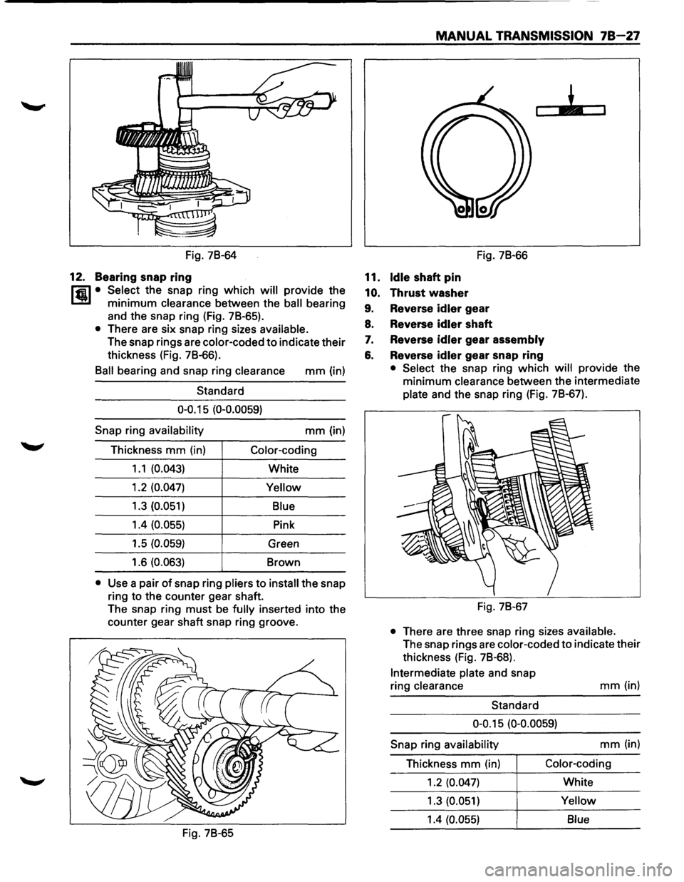
Fig. 7B-64
12. Bearing snap ring
Hi1 • Select the snap ring which will provide the
1..!!1 minimum clearance between the ball bearing
and the snap ring (Fig. 7B-65).
• There are six snap ring sizes available.
The snap rings are color-coded to indicate their
thickness (Fig. 7B-66).
Ball bearing and snap ring clearance mm (in)
Standard
0-0.15 (0-0.0059)
Snap ring availability mm (in)
Thickness
mm (in) Color-coding
1.1 (0.043) White
1.2
(0.047) Yellow
1.3 (0.051)
Blue
1.4 (0.055) Pink
1.5
(0.059) Green
1.6
(0.063) Brown
• Use a pair of snap ring pliers to install the snap
ring to the counter gear shaft.
The snap ring
must be fully inserted into the
counter gear shaft snap ring groove.
Fig. 7B-65
MANUAL TRANSMISSION 78-27
11. Idle shaft pin
10. Thrust washer
Fig. 7B-66
9. Reverse idler gear
8. Reverse
idler shaft
7. Reverse idler gear assembly
6. Reverse idler gear snap ring
• Select the snap ring which will provide the
minimum
clearance between the intermediate
plate and the snap ring (Fig. 7B-67).
Fig. 7B-67
• There are three snap ring sizes available.
The snap rings are color-coded to indicate their
thickness (Fig. 7B-68).
Intermediate plate and snap
ring
clearance
Standard
mm(in)
0-0.15 (0-0.0059)
Snap ring availability mm (in)
Thickness
mm (in) Color-coding
1.2 (0.047) White
1.3
(0.051) Yellow
1.4 (0.055)
Blue
Page 1118 of 1928
78-28 MANUAL TRANSMISSION
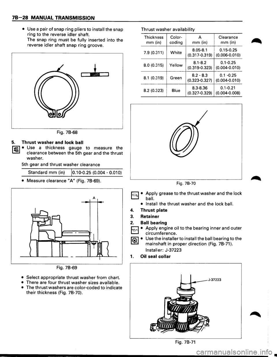
• Use a pair of snap ring pliers to install the snap
ring to the reverse
idler shaft.
The snap ring
must be fully inserted into the
reverse
idler shaft snap ring groove.
Fig. 78-68
5. Thrust washer and lock ball
l'fil • Use a thickness gauge to measure the
1.!::.1 clearance between the 5th gear and the thrust
washer.
5th gear and thrust washer
clearance
Standard mm (in) 10.10-0.25 (0.004 -0.01 0)
• Measure clearance "A" (Fig. 78-69).
A
Fig. 78-69
• Select appropriate thrust washer from chart.
• There are four thrust washer sizes available.
•
The thrust washers are color-coded to indicate
their thickness (Fig.
78-70).
Thrust washer availability
Thickn,ess Color-A Clearance
mm (in)
coding mm (in) mm (in)
7.9 (0.3:11) White 8.05-8.1 0.15-0.25
(0.317-0.319) (0.006-0.01
0)
8.0
(0.3:15) Yellow 8.1-8.2 0.1-0.25
(0.319-0.323) (0.004-0.01
0)
8.1 (0.3:19) Green 8.2-8.3 0.1 -0.25
(0.323-0.327) (0.004-0.01 0)
8.2 (0.323) Blue 8.3-8.36 0.1-0.21
(0.327-0.329) (0.004-0.008)
Fig. 78-70
1-ool • Apply grease to the thrust washer and the lock
ball.
• Install!
the thrust washer and the lock ball.
4. Thrust plate
3. Retainer
2. Ball bearing
D • Apply engine oil to the bearing inner and outer
~ circumference.
lia\1 • Use the installer to install the ball bearing to the
~ mainshaft in proper direction (Fig. 78-71 ).
Installer: J-37223
1. Oil seal collar
Fig. 78-71
•
Page 1119 of 1928
MANUAL TRANSMISSION 78-29
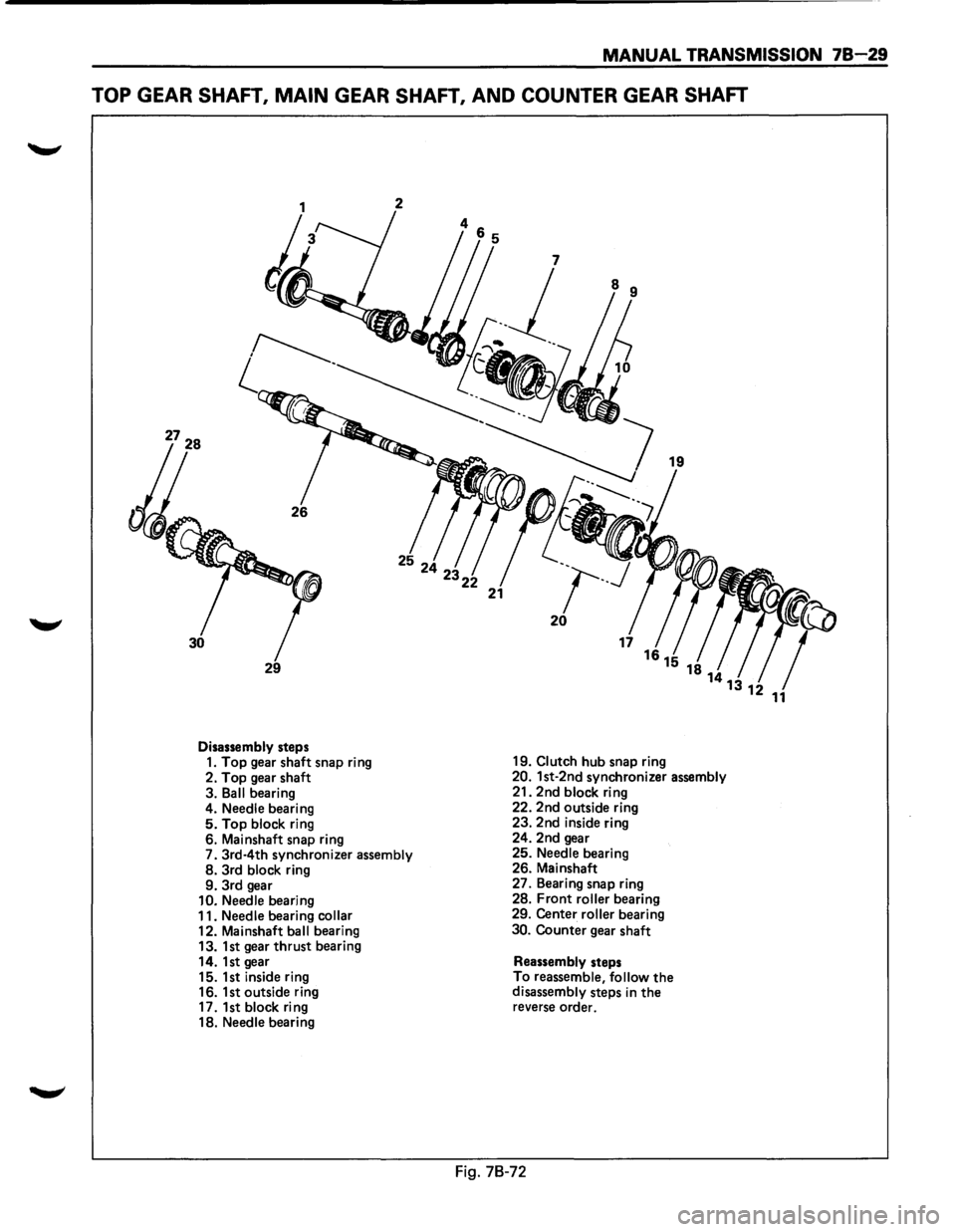
TOP GEAR SHAFT, MAIN GEAR SHAFT, AND COUNTER GEAR SHAFT
2
29
Disassembly steps 1. Top gear shaft snap ring
2.
Top gear shaft
3.
Ball bearing
4. Needle bearing 5. Top block ring
6. Mainshaft snap ring
7.
3rd·4th synchronizer assembly 8. 3rd block ring
9. 3rd gear
10. Needle bearing
11. Needle bearing collar 12. Mainshaft ball bearing
13. 1st gear thrust bearing
14. 1st gear
15. 1st inside ring
16. 1st outside ring
17. 1st
block ring
18. Needle bearing
21
19
~~~
r-.J
20
19. Clutch hub snap ring 20. 1st-2nd synchronizer assembly 21. 2nd block ring
22. 2nd outside ring
23. 2nd inside ring
24. 2nd gear
25.
Needle bearing
26. Mainshaft
27. Bearing snap ring
28.
Front roller bearing
29. Center roller bearing
30. Counter gear shaft
Reassembly steps
To reassemble, follow the disassembly steps in the reverse order.
Fig. 78-72