transmission ISUZU TROOPER 1995 Workshop Manual
[x] Cancel search | Manufacturer: ISUZU, Model Year: 1995, Model line: TROOPER, Model: ISUZU TROOPER 1995Pages: 1928
Page 1120 of 1928
78-30 MANUAL TRANSMISSION
1 .. !•1 DISASSEMBL V
1. Top gear shaft snap ring
• Use a pair of snap ring pliers to remove the
snap ring.
2. Top gear shaft
3. Ball bearing
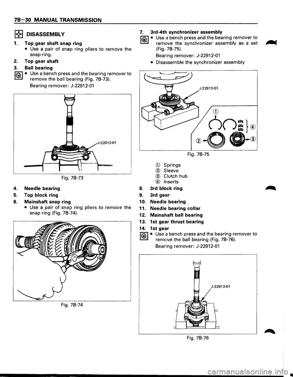
li5il • Use a bench press and the bearing remover to
~ remove the ball bearing (Fig. 7B-73).
Bearing remover: J-22912-01
2-01
Fig. 7B-73
4. Needle bearing
5. Top block ring
6. Mainshaft snap ring
• Use a pair of snap ring pliers to remove the
snap ring
(Fig. 7B-74).
Fig. 7B-74
7. 3rd-4th synchronizer assembly
li5il • Use a bench press and the bearing remover to
~ remove the synchronizer assembly as a set -.
(Fig. 7B-75).
Bearing remover:
J-22912-01
• Disassemble
the synchronizer assembly
CD Springs
® Sleeve
@ Clutch hub
@ Inserts
8. 3rd block ring
9. 3rd gear
1
0. Needle bearing Fig.
7B-75
11.
Needle bearing collar
12. Mainshaft ball bearing
13. 1st gear thrust bearing
14. 1st gear
li0\1 • Use a bench press and the bearing remover to
~ remove the ball bearing (Fig. 78-76).
Bearing remover: J-22912-01
Fig. 7B-76
•
Page 1121 of 1928
15. 1st inside ring
16. 1st outside ring
17. 1st block ring
18. Needle bearing
19. Clutch hub snap ring
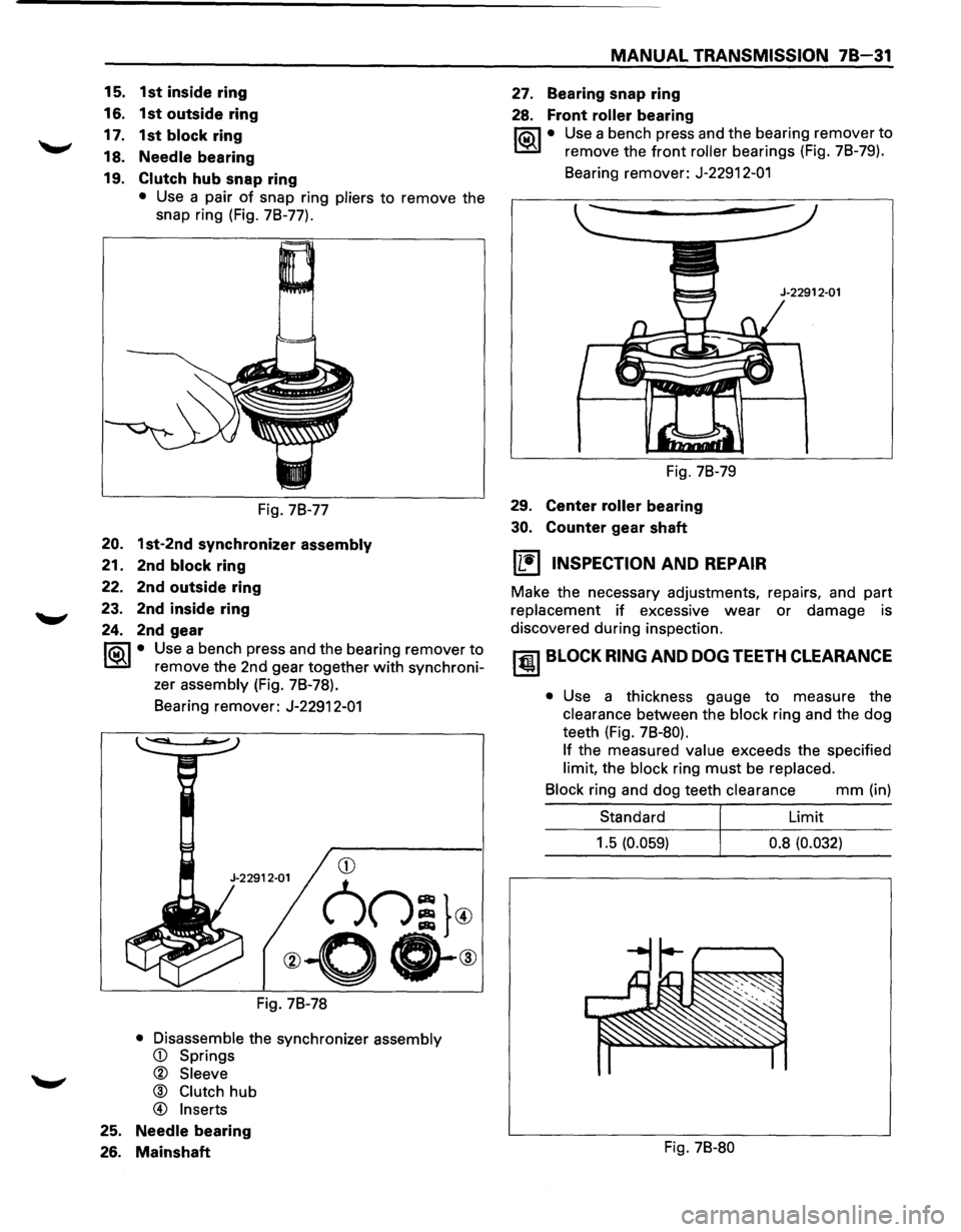
• Use a pair of snap ring pliers to remove the
snap ring (Fig. 7B-77).
Fig. 7B-77
20. 1st-2nd synchronizer assembly
21. 2nd block ring
22. 2nd outside ring
23. 2nd inside ring
24. 2nd gear
rta\1 • Use a bench press and the bearing remover to
~ remove the 2nd gear together with synchroni-
zer
assembly (Fig. 7B-78).
Bearing remover:
J-22912-01
Fig. 7B-78
• Disassemble the synchronizer assembly
® Clutch hub
@ Inserts
25. Needle bearing
26. Mainshaft
MANUAL TRANSMISSION 78-31
27. Bearing snap ring
28. Front roller bearing
rta\1 • Use a bench press and the bearing remover to
~ remove the front roller bearings (Fig. 7B-79).
Bearing remover:
J-22912-01
Fig. 7B-79
29.
Center roller bearing
30. Counter gear shaft
~ INSPECTION AND REPAIR
Make the necessary adjustments, repairs, and part
replacement if excessive wear or damage is
discovered during inspection.
~ BLOCK RING AND DOG TEETH CLEARANCE
• Use a thickness gauge to measure the
clearance between the block ring and the dog
teeth (Fig.
7B-80).
If
the measured value exceeds the specified
limit, the block ring must be replaced.
Block
ring and dog teeth clearance mm (in)
Standard Limit
1.5
(0.059) 0.8 (0.032)
Fig. 7B-80
Page 1122 of 1928
7B-32 MANUAL TRANSMISSION
~1ST-2ND SYNCHRONIZER (3-CONE)
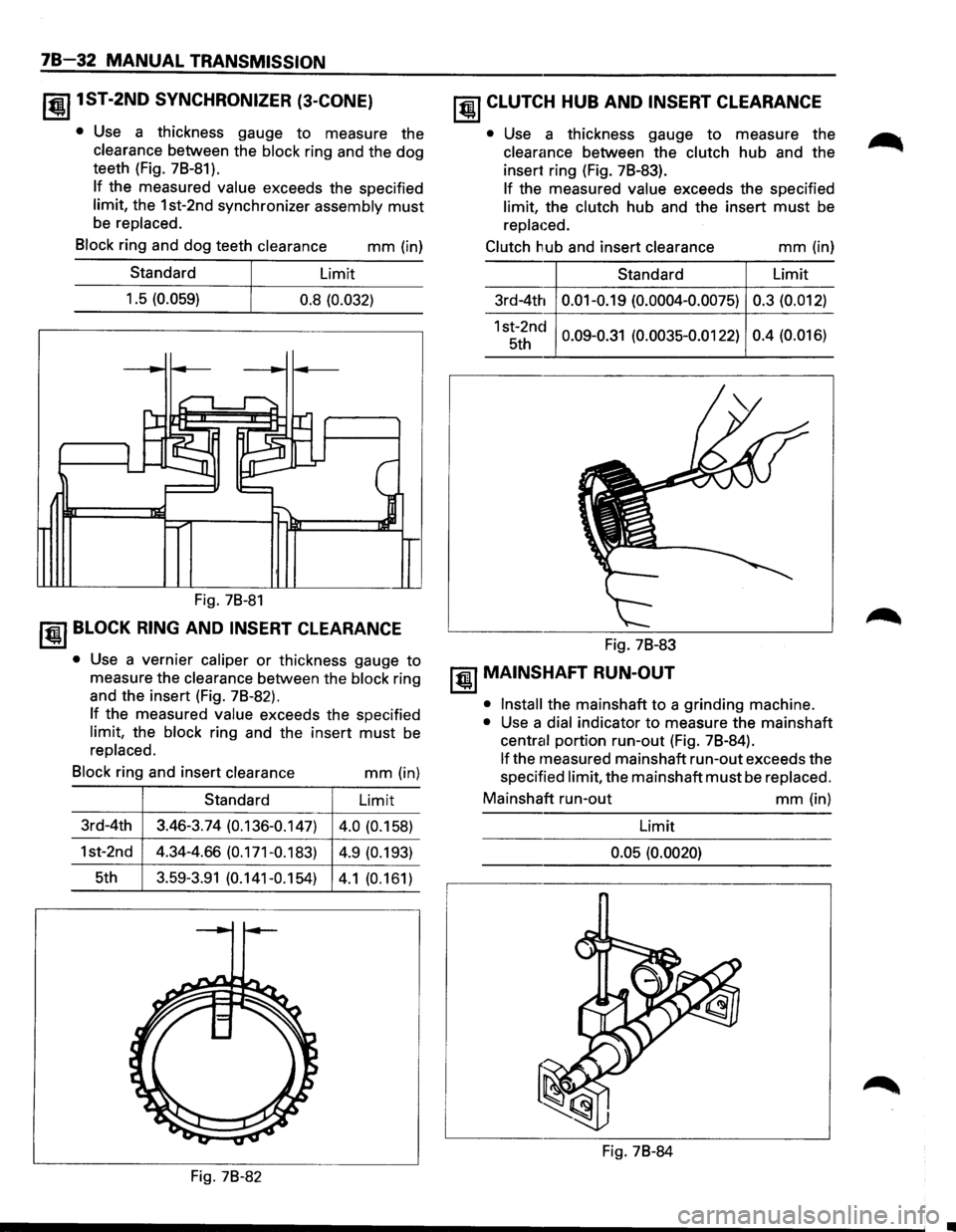
• Use a thickness gauge to measure the
clearance between the block ring and the dog
teeth (Fig. 7B-81).
If the measured value exceeds the specified
limit, the 1st-2nd synchronizer assembly must
be replaced.
Block
ring and dog teeth clearance mm (in)
Standard Limit
1.5
(0.059) 0.8 (0.032)
Fig. 7B-81
~~~ BLOCK RING AND INSERT CLEARANCE
• Use a vernier caliper or thickness gauge to
measure the
clearance between the block ring
and the insert (Fig. 7B-82).
If the measured value exceeds the specified
limit, the block ring and the insert must be
replaced.
Block
ring and insert clearance mm (in)
Standard Limit
3rd-4th 3.46-3.74
(0.136-0.147)
4.0 (0.158)
1st-2nd
4.34-4.66 (0.171-0.183) 4.9 (0.193)
5th 3.59-3.91 (0.141-0.154) 4.1 (0.161)
Fig. 78-82
~ CLUTCH HUB AND INSERT CLEARANCE
• Use a thickness gauge to measure the
clearance between the clutch hub and the
insert ring (Fig. 7B-83).
If the measured value exceeds the specified
limit, the clutch hub and the insert must be
replaced.
Clutch
hub and insert clearance
Standard
3rd-4th
0.01-0.19 (0.0004-0.0075)
1st-2nd 0.09-0.31 (0.0035-0.0122) 5th
Fig. 7B-83
~ MAINSHAFT RUN-OUT
mm (in)
Limit
0.3 (0.012)
0.4 (0.016)
• Install
the mainshaft to a grinding machine.
• Use a dial indicator to measure the mainshaft
central portion run-out (Fig. 7B-84).
If the measured mainshaft run-out exceeds the
specified
limit, the mainshaft must be replaced.
Mainshaft run-out mm (in)
Limit
0.05 (0.0020)
Fig. 7B-84
Page 1123 of 1928
~ GEAR INSIDE DIAMETER
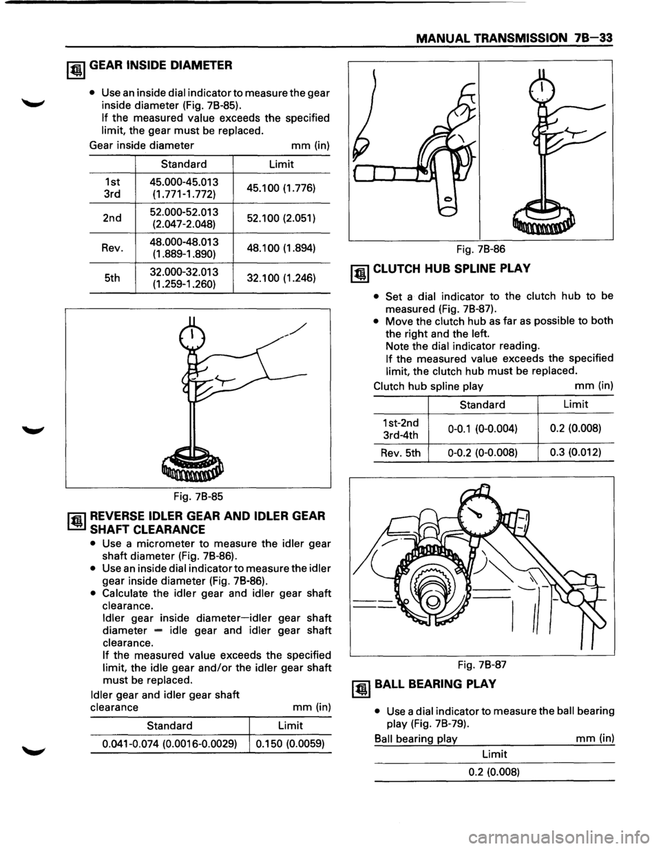
• Use an inside dial indicator to measure the gear
inside diameter (Fig. 78-85).
If the measured value exceeds the specified
limit, the gear
must be replaced.
Gear inside diameter
mm (in)
Standard Limit
1st
45.000-45.013 45.100 (1.776)
3rd (1.771-1.772)
2nd
52.000-52.013 52.100 (2.051)
(2.047-2.048)
Rev.
48.000-48.013 48.1 00 (1 .894)
(1.889-1.890)
5th
32.000-32.013 32.100 (1.246)
(1.259-1.260)
Fig. 78-85
l'fil REVERSE IDLER GEAR AND IDLER GEAR
l..!lil SHAFT CLEARANCE
• Use a micrometer to measure the idler gear
shaft diameter (Fig. 78-86).
• Use an inside dial indicator to measure the idler
gear inside diameter (Fig. 78-86).
• Calculate the idler gear and idler gear shaft
clearance.
Idler gear inside diameter-idler gear shaft
diameter
= idle gear and idler gear shaft
clearance.
If the measured value exceeds the specified
limit, the idle gear
and/or the idler gear shaft
must be replaced.
Idler gear and idler gear shaft
clearance
Standard
mm (in)
Limit
0.041-0.074 (0.0016-0.0029) 0.150 (0.0059)
MANUAL TRANSMISSION 78-33
Fig. 78-86
~ CLUTCH HUB SPLINE PLAY
• Set a dial indicator to the clutch hub to be
measured (Fig. 78-87).
• Move the clutch hub as far as possible to both
the right and the left.
Note the dial indicator reading.
If the measured value exceeds the specified
limit, the clutch hub
must be replaced.
Clutch hub spline play
mm (in)
Standard
1st-2nd
0-0.1 (0-0.004) 3rd-4th
Rev. 5th 0-0.2 (0-0.008)
Fig. 78-87
~BALL BEARING PLAY
Limit
0.2 (0.008)
0.3 (0.012)
•
Use a dial indicator to measure the ball bearing
play (Fig. 78-79).
Ball bearing play
mm (in)
Limit
0.2 (0.008)
Page 1124 of 1928
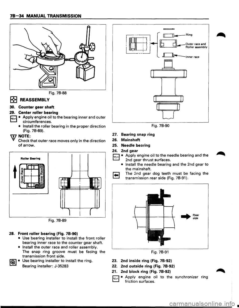
78-34 MANUAL TRANSMISSION
Fig. 78-88
l•!•l REASSEMBLY
30. Counter gear shaft
29. Center roller bearing
r:::::1 • Apply engine oil to the bearing inner and outer
L.:::.l circumferences.
• Install the roller bearing in the proper direction
(Fig. 78-89).
'q7 NOTE:
VI Check that outer race moves only in the direction
of arrow.
Roller Beering
t
Fig. 78-89
28. Front roller bearing (fig. 78-90)
• Use bearing installer to install the front roller
bearing inner race to the counter gear shaft.
• Install the outer race and roller assembly.
The snap ring groove must be facing the
transmission
front side.
1®..1• Use bearing installer to install the ring.
Bearing
installer: J-35283
=
rr=:=n--Ring
~ Outer race and ~Roller assembly
c:::Jb..-lnner race
Fig. 78-90
27. Bearing snap ring
26. Mainshaft
25. Needle bearing
24. 2nd gear
D • Apply engine oil to the needle bearing and the
L.:::.l 2nd gear thrust surfaces.
• Install the needle bearing and the 2nd gear to
the mainshaft.
r:;::] The 2nd gear dog teeth must be facing the
~ transmission rear side (Fig. 78-91 ) .
Fig. 78-91
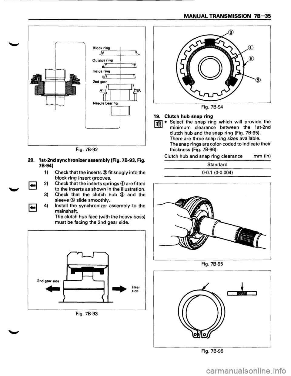
23. 2nd inside ring (Fig. 78-92)
22. 2nd
outside ring (Fig. 78-92)
21. 2nd
bloc:k ring (Fig. 78-92)
.. Rear
side
D • Apply engine oil to the synchronizer ring
L.:::.l friction surfaces.
•
Page 1125 of 1928
Block ring
Outside..., rr-in~g-+------.=
Inside ring ,..r--+---n
Fig. 78-92
20. 1st-2nd synchronizer assembly (Fig. 78-93, Fig.
78-94)
1)
2)
3)
4)
Check that the inserts® fit snugly into the
block ring insert grooves.
Check that the inserts
springs@ are fitted
to the inserts as shown in the illustration.
Check that the clutch hub @ and the
sleeve® slide smoothly.
Install
the synchronizer assembly to the
mainshaft.
The
clutch hub face (with the heavy boss)
must be facing the 2nd gear side.
2nd gear side
Fig. 78-93
Rear
side
MANUAL TRANSMISSION 78-35
Fig. 78-94
19. Clutch hub snap ring
l'fi1 • Select the snap ring which will provide the
1..!:!1 minimum clearance between the 1st-2nd
clutch hub and the snap ring (Fig. 78-95).
There are three snap ring sizes
available.
The snap rings are color-coded to indicate their
thickness (Fig. 78-96).
Clutch hub and snap ring clearance mm (in)
Standard
0-0.1 (0-0.004)
Fig. 78-95
Fig. 78-96
Page 1126 of 1928
78-36 MANUAL TRANSMISSION
Snap ring availability mm (in)
Thickness
Color-coding
1.80 (0.071)
White
1.85
(0.073) Yellow
1.90 (0.075)
Blue
•
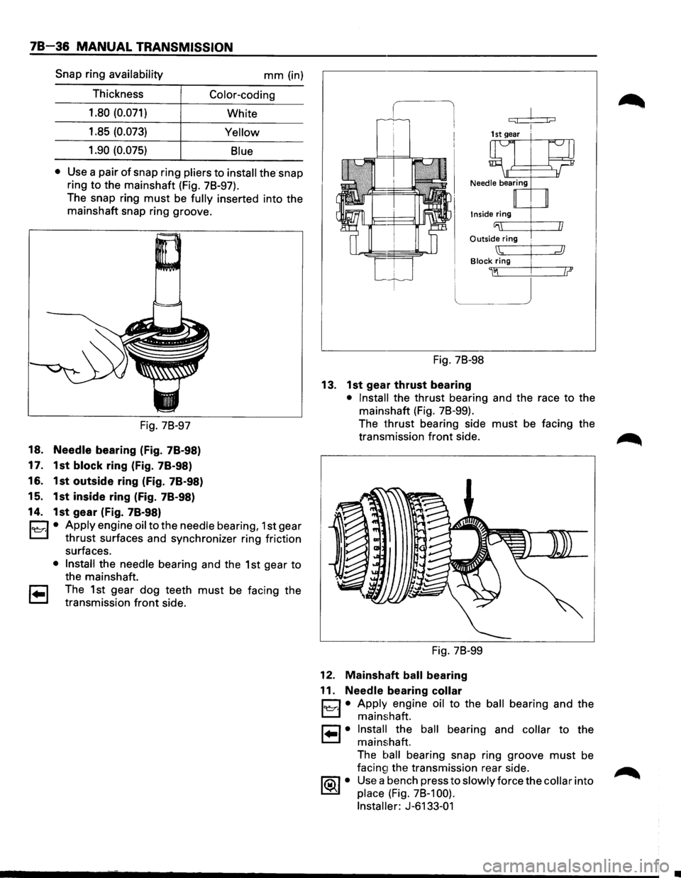
Use a pair of snap ring pliers to install the snap
ring
to the mainshaft (Fig. 78-97).
The snap ring
must be fully inserted into the
mainshaft snap ring groove.
Fig. 78-97
18. Needle bearing (Fig. 78-98)
17. 1st
block ring (Fig. 78-98)
16. 1st outside ring (Fig. 78-98)
15. 1st inside ring (Fig. 78-98)
14. 1st gear (Fig. 78-98)
C1 • Apply engine oil to the needle bearing, 1st gear
L::l thrust surfaces and synchronizer ring friction
surfaces.
• Install the needle bearing and the 1st gear to
the mainshaft.
1 .. 1 The 1st gear dog teeth must be facing the
transmission
front side.
c:;! j;::::J
Inside ring
Outside ring .
Block Zig I
~~ .
Fig. 78-98
13. 1st gear thrust bearing
• Install the thrust bearing and the race to the
mainshaft (Fig. 78-99).
The
thrust bearing side must be facing the
transmission
front side.
Fig. 78-99
12. Mainshaft ball bearing
11.
Needle bearing collar
1~·1 • Apply engine oil to the ball bearing and the
mainshaft.
1 .. 1• Install the ball bearing and collar to the
mainshaft.
The
ball bearing snap ring groove must be
facin~1 the transmission rear side.
1®..1 • Use a bench press to slowly force the collar into
place (Fig. 78-1 00).
Installer:
J-6133-01
Page 1127 of 1928
MANUAL TRANSMISSION 78-37
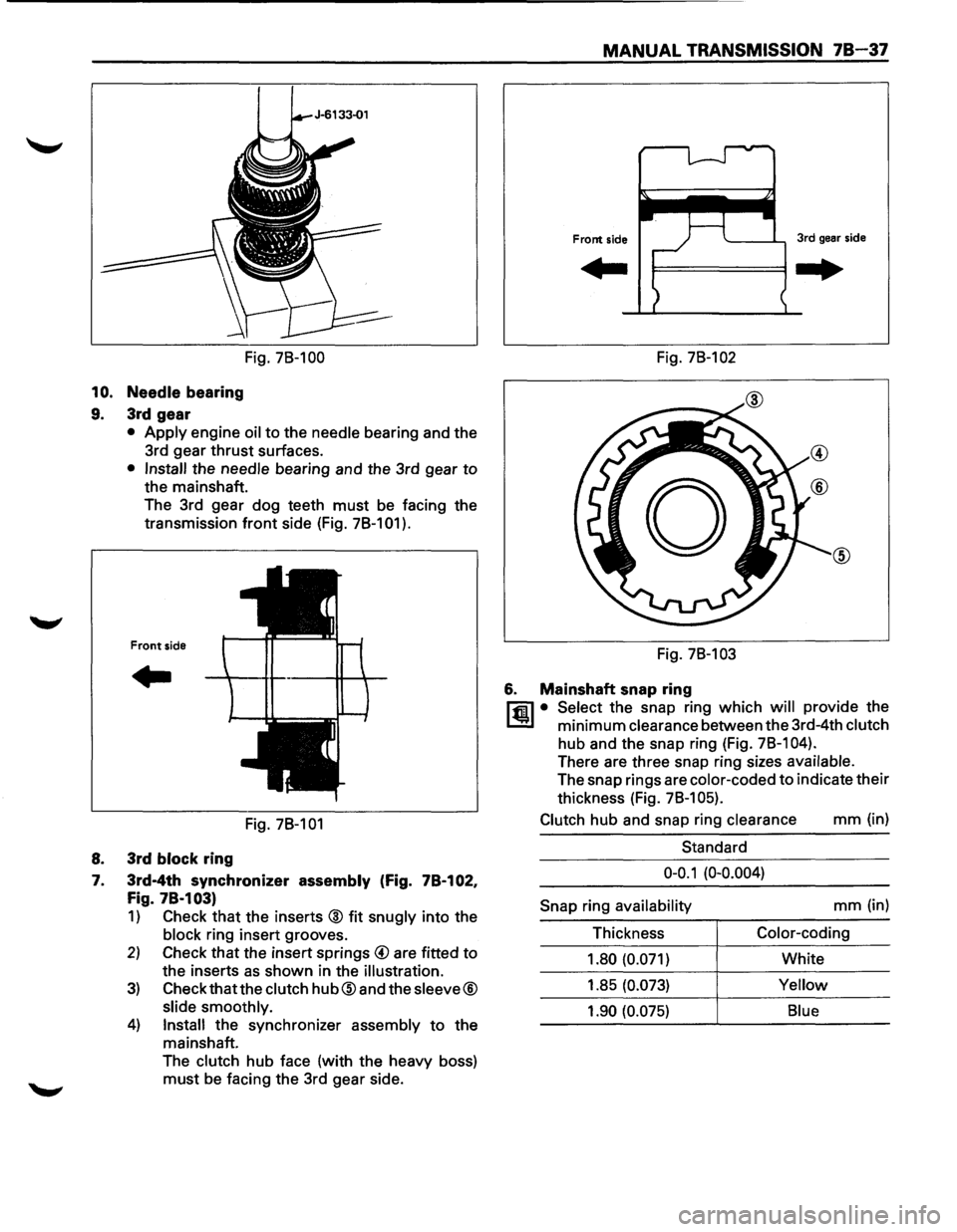
Fig. 78-100 Fig. 78-102
10. Needle bearing
9. 3rd gear
• Apply engine oil to the needle bearing and the
3rd gear
thrust surfaces.
• Install the needle bearing and the 3rd gear to
the mainshaft.
The 3rd gear dog teeth
must be facing the
transmission
front side (Fig. 78-101 ).
Front side
..
Fig. 78-101
8. 3rd block ring
7. 3rd-4th synchronizer assembly (Fig. 78-102,
Fig. 78·103)
1) Check that the inserts @ fit snugly into the
block ring insert grooves.
2) Check that the insert springs @ are fitted to
the inserts as shown in the illustration.
3) Check that the clutch hub@and the sleeve®
slide smoothly.
4) Install the synchronizer assembly to the
mainshaft.
The
clutch hub face (with the heavy boss)
must be facing the 3rd gear side. Fig.
78-103
6. Mainshaft snap ring
l"fil • Select the snap ring which will provide the
l..!l!l minimum clearance between the 3rd-4th clutch
hub and the snap ring (Fig. 78-1 04).
There are three snap ring sizes available.
The snap rings are color-coded to indicate their
thickness (Fig.
78-1 05).
Clutch
hub and snap ring clearance mm (in)
Standard
0-0.1 (0-0.004)
Snap
ring availability mm (in)
Thickness
Color-coding
1.80 (0.071)
White
1.85
(0.073) Yellow
1.90 (0.075) Blue
Page 1128 of 1928
78-38 MANUAL TRANSMISSION
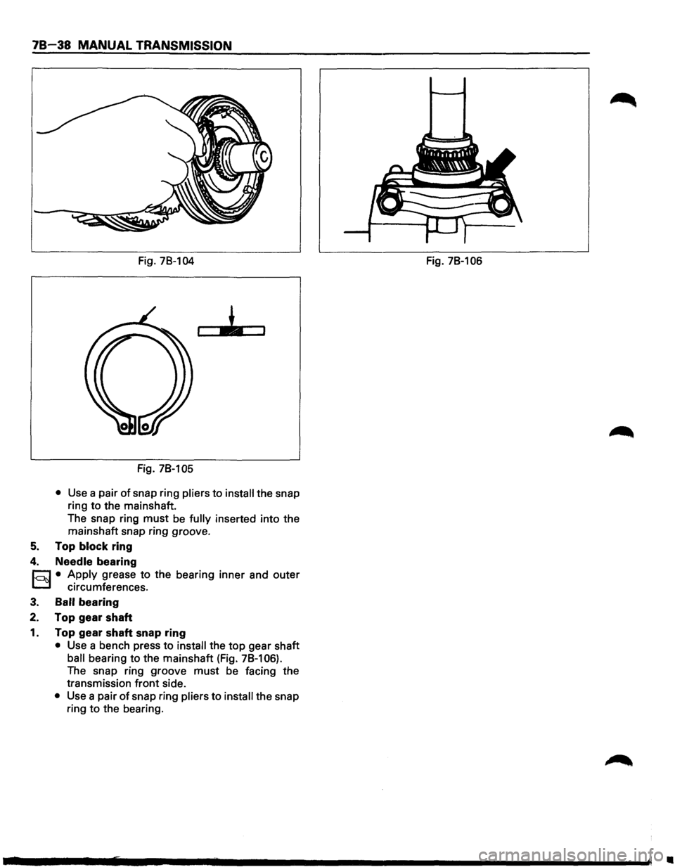
Fig. 78-104
Fig. 78-105
• Use a pair of snap ring pliers to install the snap
ring to the mainshaft.
The snap ring
must be fully inserted into the
mainshaft snap ring groove.
5. Top block ring
4. Needle bearing
r::J • Apply grease to the bearing inner and outer
D circumferences.
3. Ball bearing
2. Top gear shaft
1. Top gear shaft snap ring
• Use a bench press to install the top gear shaft
ball bearing to the mainshaft (Fig. 78-106).
The snap ring groove
must be facing the
transmission
front side.
• Use a pair of snap ring pliers to install the snap
ring
to the bearing. Fig.
78-106
•
Page 1129 of 1928
MANUAL TRANSMISSION 78-39
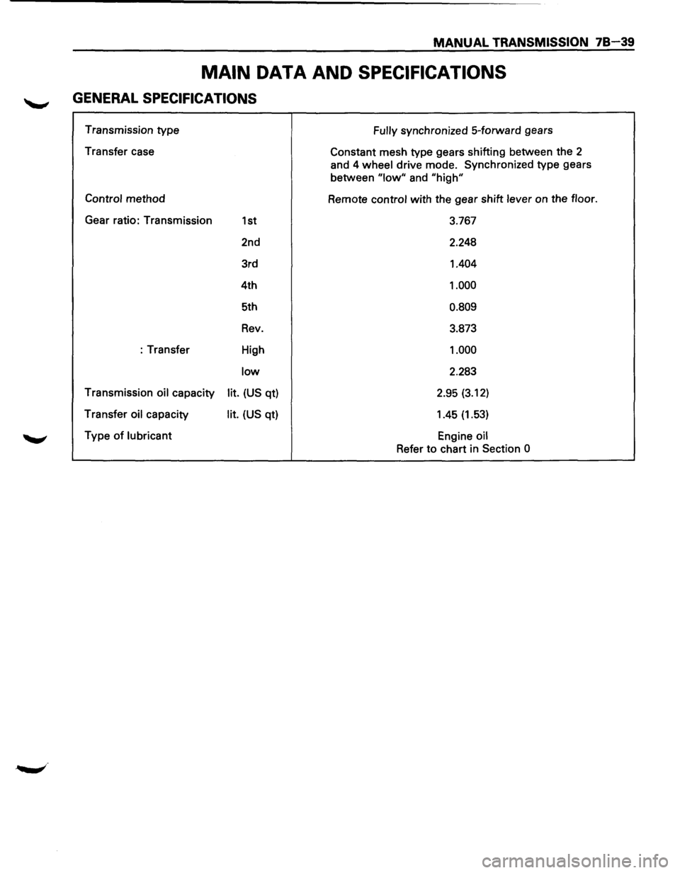
MAIN DATA AND SPECIFICATIONS
GENERAL SPECIFICATIONS
Transmission type
Transfer case
Control method
Gear ratio: Transmission
1st
2nd
3rd
4th
5th
Rev.
:Transfer High
low
Transmission oil capacity lit. (US qt)
Transfer
oil capacity lit. (US qt)
Type
of lubricant Fully
synchronized
5-forward gears
Constant mesh type gears shifting between the
2
and 4 wheel drive mode. Synchronized type gears
between
"low" and "high"
Remote control with the gear shift lever on the floor.
3.767
2.248
1.404
1.000
0.809
3.873
1.000
2.283
2.95
(3.12)
1.45 (1.53)
Engine oil
Refer to chart in Section 0