wheel ISUZU TROOPER 1995 Workshop Manual
[x] Cancel search | Manufacturer: ISUZU, Model Year: 1995, Model line: TROOPER, Model: ISUZU TROOPER 1995Pages: 1928
Page 1767 of 1928
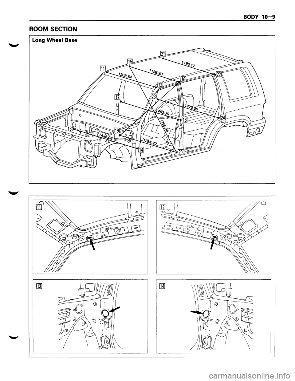
BODY 10-9
ROOM SECTION
Long Wheel Base
Page 1770 of 1928
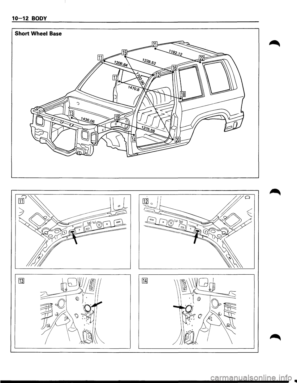
10-12 BODY
Short Wheel Base
\I\~
\.1@ 0~
~'
--------------------------------------------~
Page 1774 of 1928
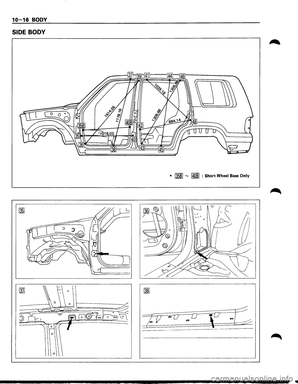
10-16 BODY
SIDE BODY
* I35BI """ 14081 : Short Wheel Base Only
Page 1814 of 1928
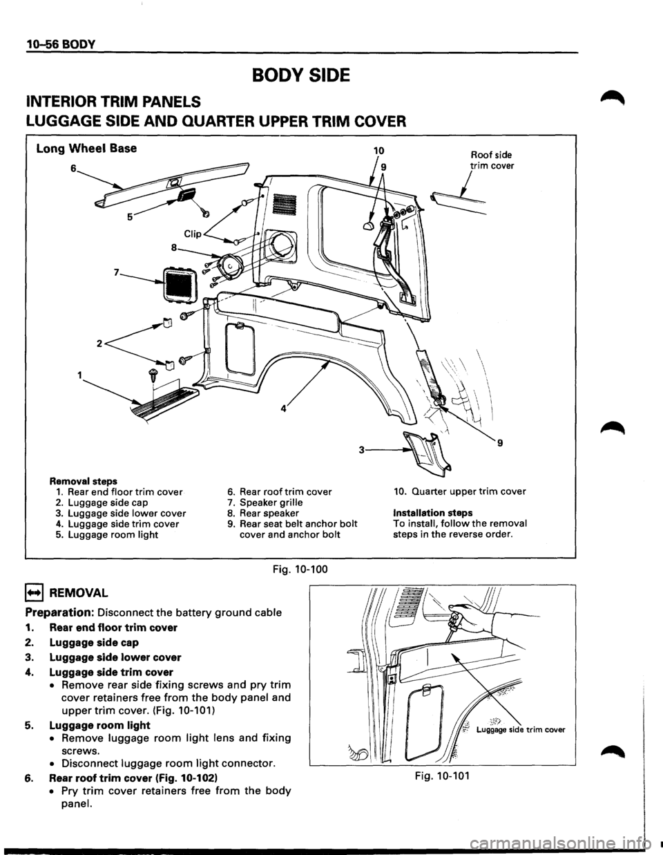
10-56 BODY
BODY SIDE
INTERIOR TRIM PANELS
LUGGAGE
SIDE AND QUARTER UPPER TRIM COVER
Long Wheel Base
6
1
Removal steps 1. Rear end floor trim cover 2. Luggage side cap 3. Luggage side lower cover 4. Luggage side trim cover 5. Luggage room light
1+•1 REMOVAL
6. Rear roof trim cover
7. Speaker grille 8. Rear speaker 9. Rear seat belt anchor bolt cover and anchor bolt
Fig. 10-100
Preparation: Disconnect the battery ground cable
1. Rear end floor trim cover
2. Luggage side cap
3. Luggage side lower cover
4. Luggage side trim cover
• Remove rear side fixing screws and pry trim
cover retainers free from the body panel and
upper trim cover. (Fig. 10-101)
5. Luggage room light
• Remove luggage room light lens and fixing
screws.
• Disconnect luggage room light connector.
6. Rear roof trim cover (Fig. 10-102)
• Pry trim cover retainers free from the body
panel.
Roof side trim cover
, _ _.,,..~
~
9
10. Quarter upper trim cover
Installation steps
To install, follow the removal
steps in
the reverse order.
~~F:r Luggage side trim cover
Fig. 10-101
•
Page 1816 of 1928
10-58 BODY
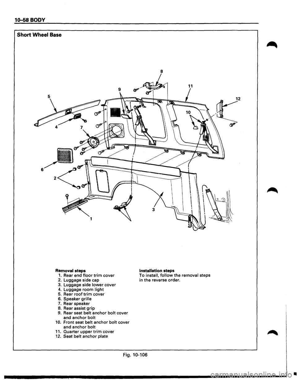
Short Wheel Base
Removal steps 1. Rear end floor trim cover 2. Luggage side cap 3. Luggage side lower cover 4. Luggage room light 5. Rear roof trim cover 6. Speaker grille
7. Rear speaker 8. Rear assist grip 9. Rear seat belt anchor bolt cover
and anchor bolt 10. Front seat belt anchor bolt cover
and anchor bolt 11. Quarter upper trim cover 12. Seat belt anchor plate
Installation steps To install, follow the removal steps
in the reverse order.
Fig. 10-106
•
Page 1824 of 1928
10-66 BODY
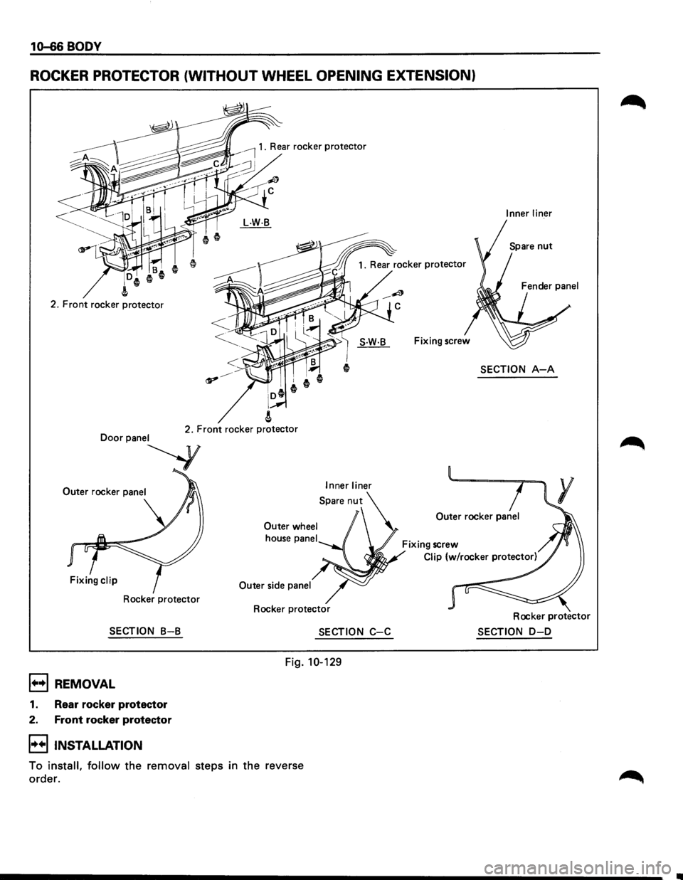
ROCKER PROTECTOR (WITHOUT WHEEL OPENING EXTENSION)
2. Front rocker protector
2. Front rocker protector
Outer rocker panel Inner liner
Outer wheel
Outer side panel
Rocker protector
Rocker protector
SECTION 8-B SECTION C-C
Fig. 10-129
B REMOVAL
1. Rear rocker protector
2. Front rocker protector
l++ltNSTALLATION
To install, follow the removal steps in the reverse
order.
Inner liner
SECTION A-A
Rocker protector
SECTION D-D
Page 1825 of 1928
BODY 10-67
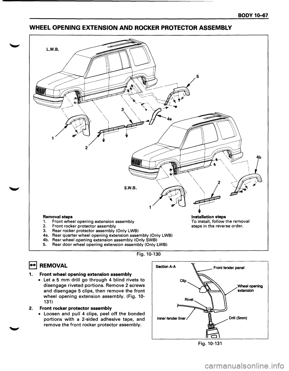
WHEEL OPENING EXTENSION AND ROCKER PROTECTOR ASSEMBLY
L.W.B.
1
2
S.W.B.
1
Removal steps
1. Front wheel opening extension assembly 2. Front rocker protector assembly 3. Rear rocker protector assembly (Only LWB) 4a. Rear quarter wheel opening extension assembly (Only LWB)
4b. Rear
wheel opening extension assembly (Only SWB) 5. Rear door wheel opening extension assembly (Only LWB)
Fig. 10-130
E] REMOVAL
1. Front wheel opening extension assembly
• Let a 5 mm drill go through 4 blind rivets to
disengage riveted portions. Remove 2 screws
and disengage 5
clips, then remove the front
wheel opening extension assembly. (Fig. 10-
131)
2.
Front rocker protector assembly
• Loosen and pull 4 clips, peel off the bonded
portions with a 2-sided adhesive tape, and
remove the front rocker protector assembly.
Section A-A
Inner fender liner
5
2
:;t
t
Installation steps
To install, follow the removal steps in the reverse order.
Front fender panel
4b
Wheel opening extension
Page 1826 of 1928
1o-&8 BODY
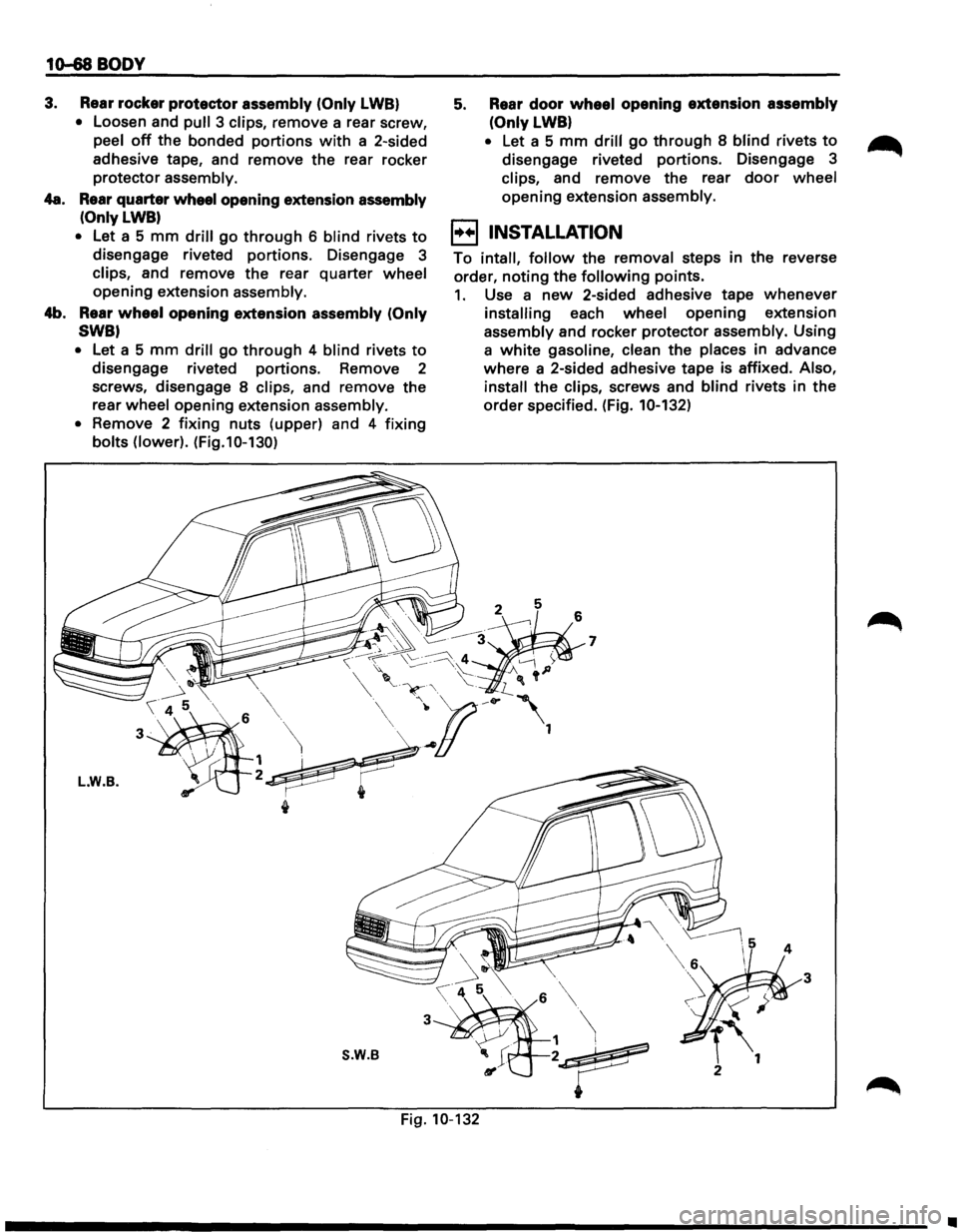
3. Rear rocker protector assembly (Only LWB}
• Loosen and pull 3 clips, remove a rear screw,
peel
off the bonded portions with a 2-sided
adhesive tape, and remove the rear rocker
protector assembly.
4a. Rear quarter wheel opening extension assembly
(OnlyLWB)
•
Let a 5 mm drill go through 6 blind rivets to
disengage riveted portions. Disengage 3
clips, and remove the rear quarter wheel
opening extension assembly.
4b. Rear
wheel opening extension assembly (Only
SWB}
•
Let a 5 mm drill go through 4 blind rivets to
disengage riveted portions. Remove 2
screws, disengage 8
clips, and remove the
rear wheel opening extension assembly.
• Remove 2 fixing nuts (upper) and 4 fixing
bolts (lower). (Fig.10-130)
L.W.B.
3
S.W.B
5. Rear door wheel opening extension assembly
(Only LWB}
• Let a 5 mm drill go through 8 blind rivets to
disengage riveted portions. Disengage 3
clips, and remove the rear door wheel
opening extension assembly.
EJ INSTALLATION
To intall, follow the removal steps in the reverse
order, noting
the following points.
1. Use a new 2-sided adhesive tape whenever
installing each wheel opening extension
assembly and rocker protector assembly. Using
a
white gasoline, clean the places in advance
where a 2-sided adhesive tape is affixed. Also,
install the clips, screws and blind rivets in the
order specified. (Fig. 10-132)
5
6
3
~~
• Fig. 10-132
•
Page 1827 of 1928
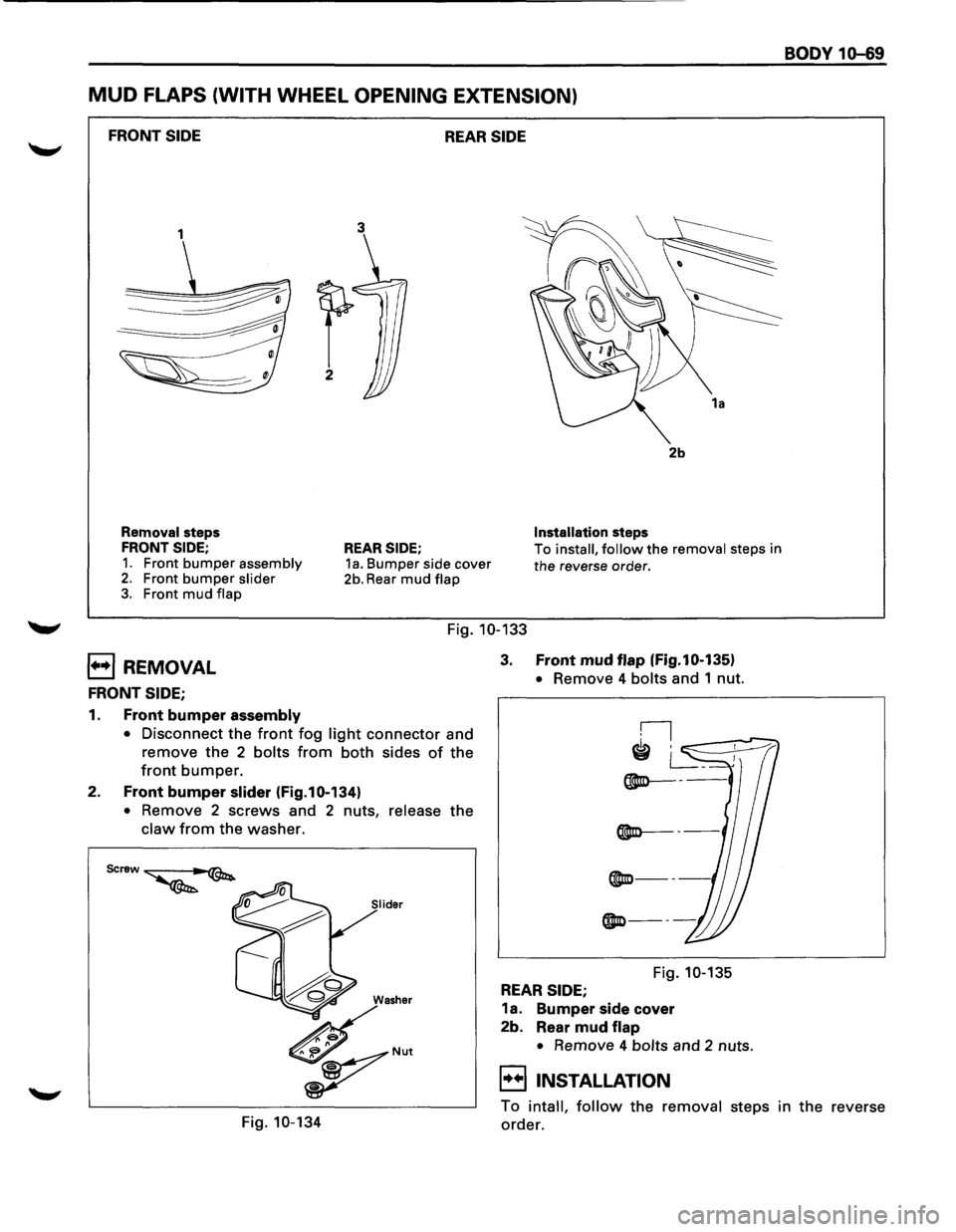
MUD FLAPS (WITH WHEEL OPENING EXTENSION)
FRONT SIDE REAR SIDE
1
Removal steps
FRONT SIDE;
1. Front bumper assembly 2. Front bumper slider 3. Front mud flap
3
REAR SIDE; 1a. Bumper side cover
2b. Rear mud flap
2b
Installation steps
To
install, follow the removal steps in
the reverse order.
Fig. 10-133
E) REMOVAL
FRONT SIDE;
1. Front bumper assembly
• Disconnect the front fog light connector and
remove the 2 bolts from both sides of the
front bumper.
2. Front bumper slider (Fig.10-134)
• Remove 2 screws and 2 nuts, release the
claw from the washer.
3. Front mud flap (Fig.10-135l
• Remove 4 bolts and 1 nut.
®Io---
Fig. 10-135
REAR SIDE;
1a. Bumper side cover
2b. Rear mud flap
• Remove 4 bolts and 2 nuts.
EIINSTALLATION
BODY 10-69
Fig. 10-134
To intall, follow the removal steps in the reverse
order.
Page 1845 of 1928
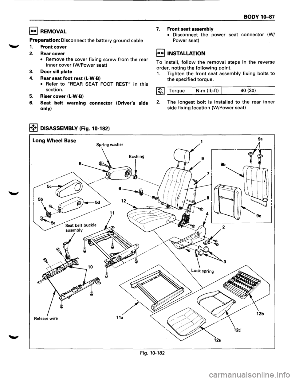
1++1 REMOVAL
Preparation:
Disconnect the battery ground cable
1. Front cover
2. Rear cover
• Remove the cover fixing screw from the rear
inner cover (W/Power seat)
3. Door sill plate
4. Rear seat foot rest (l·W·B)
• Refer to "REAR SEAT FOOT REST" in this
section.
5. Riser cover (L·W·B)
6. Seat belt warning connector (Driver's side
only)
1•!•1 DISASSEMBLY (Fig. 10-182)
Long Wheel Base Spring washer
Bushing
5
Release wire
BODY 10-87
7. Front seat assembly
•
Disconnect the power seat connector (W/
Power seat)
I++IINSTALLATION
To install, follow the removal steps in the reverse
order,
noting the following point.
1. Tighten the front seat assembly fixing bolts to
the specified torque.
~~~ Torque N-m (lb·ft) 40 (30)
2. The longest bolt is installed to the rear inner
side fixing location (W/Power seat)
9a
Fig. 10-182