sensor ISUZU TROOPER 1995 Workshop Manual
[x] Cancel search | Manufacturer: ISUZU, Model Year: 1995, Model line: TROOPER, Model: ISUZU TROOPER 1995Pages: 1928
Page 1693 of 1928
Supplemental Restrai~t System 9J-69
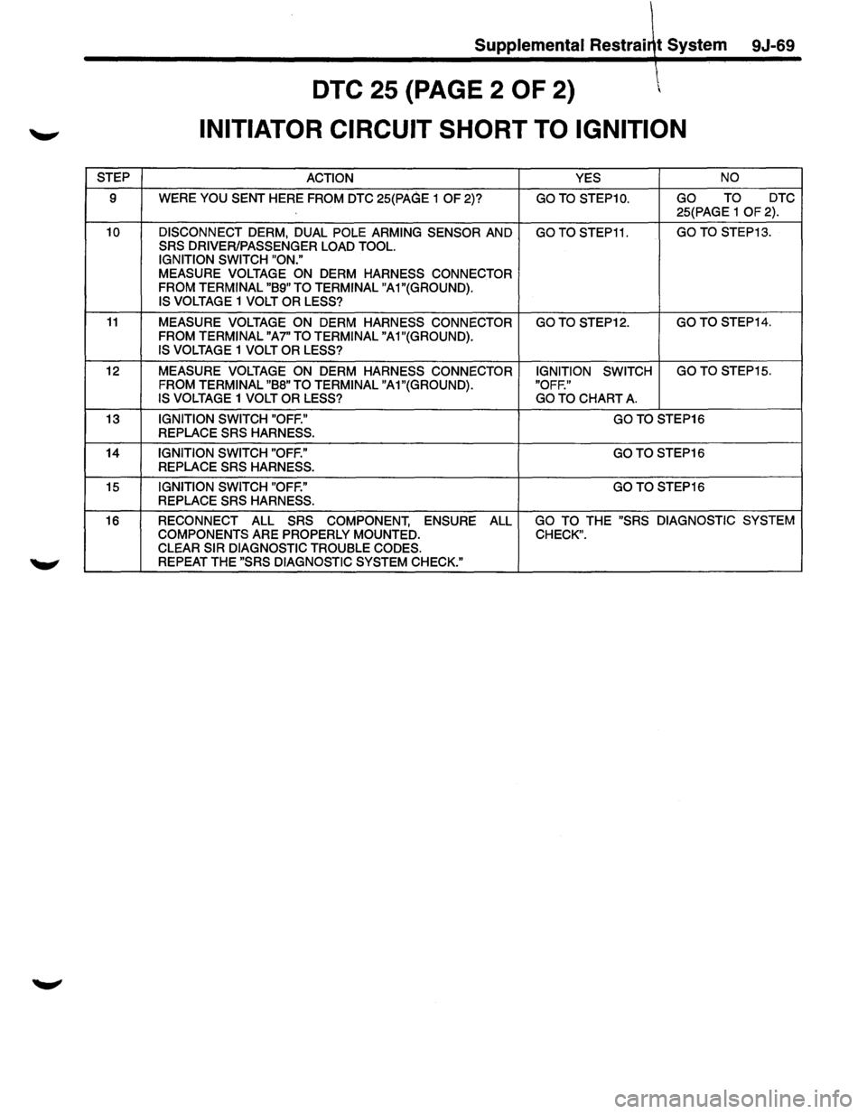
DTC 25 {PAGE 2 OF 2)
INITIATOR CIRCUIT SHORT TO IGNITION
STEP ACTION YES NO
9 WERE YOU SENT HERE FROM DTC 25(PAGE 1 OF 2)? GO TO STEP1 0. GO TO DTC
25(PAGE 1
OF 2).
10 DISCONNECT DERM, DUAL POLE ARMING SENSOR AND GO TO STEP11. GO TO STEP13.
SRS DRIVER/PASSENGER LOAD TOOL.
IGNITION SWITCH "ON."
MEASURE VOLTAGE ON DERM HARNESS CONNECTOR
FROM TERMINAL "89" TO TERMINAL
"A1"(GROUND).
IS
VOLTAGE 1 VOLT OR LESS?
11 MEASURE VOLTAGE ON DERM HARNESS CONNECTOR GO TO STEP12. GO TO STEP14.
FROM
TERMINAL "A7" TO TERMINAL "A1"(GROUND). IS VOLTAGE 1 VOLT OR LESS?
12
MEASURE VOLTAGE ON DERM HARNESS CONNECTOR IGNITION SWITCH GO
TO STEP15.
FROM
TERMINAL "88" TO TERMINAL "A1"(GROUND). "OFF."
IS VOLTAGE 1 VOLT OR LESS? GO TO CHART A.
13 IGNITION SWITCH "OFF." GOTO STEP16
REPLACE
SRS HARNESS.
14
IGNITION SWITCH "OFF." GOTO STEP16
REPLACE
SRS HARNESS.
15
IGNITION SWITCH "OFF." GO TO STEP16
REPLACE SRS HARNESS.
16 RECONNECT ALL
SRS COMPONENT, ENSURE ALL GO TO THE "SRS DIAGNOSTIC SYSTEM
COMPONENTS
ARE PROPERLY MOUNTED. CHECK". CLEAR SIR DIAGNOSTIC TROUBLE CODES. REPEAT THE "SRS DIAGNOSTIC SYSTEM CHECK."
Page 1698 of 1928

9J-74 Supplemental Restraint System
---~
DTC31 \"'
DRIVER LOOP ENERGY RESERVE FEED OPEN
CIRCUIT DESCRIPTION
During the "Continuous Monitoring" tests the DERM
monitors the
voltage at "Driver Source Sense" terminal
"AS." When the circuit is operating normally the
measured voltage will be slightly less than "Driver 36
VLR."
If the "Driver 36 VLR" circuit opens the voltage
measured at "Driver Source Sense" will decrease to
slightly less than "Ignition 1" voltage. When the voltage
measured at "Driver Source Sense" is within a specified
range of
"Ignition 1" for SOO milliseconds DTC 31 is set.
DTC WILL SET WHEN
The voltage measured at "Driver Source Sense" terminal
"AS"
is within a specified range of "Ignition 1" for SOO
milliseconds. This test is run every 100 milliseconds
during "Continuous Monitoring" tests.
ACTION TAKEN
DERM turns "ON" the "AIR BAG" warning lamps and sets
a diagnostic
trouble code.
DTC WILL CLEAR WHEN
The voltage measured at "Driver Source Sense" terminal
"AS"
is outside the specified range of "Ignition 1" which
sets the diagnostic
trouble code, for SOO milliseconds.
TO IGNITION SWITCH
FUSE! SRS C-24 lOA , ... R D
FUSE SRS C-23 IDA , ...
DTC CHART TEST DESCRIPTION
Number(s) below refer to step number(s) on the
diagnostic chart.
2. This test checks for an open in the "Driver 36VLR"
circuit.
3. This test checks for a high resistance, but not an
open, in the "Driver Source Sense" circuit.
4. This test checks for a short from the "Driver Source
Sense" circuit to 8+.
s. This test determines whether the malfunction is due
to the
dual pole arming sensor.
DIAGNOSTIC AIDS
An intermittent condition is likely to be caused by a poor
connection at arming sensor
terminal "4" or "6", poor
connection at DERM
terminal "A4" or "AS", an open in
CKT 1811 or CKT 1812, or an open inside the dual pole
arming sensor.
IGNITION1
IGNITION1
DRIVER SOURCE SENSE DRIVER 38VLR PASS.3eVLR PASS. SOURCE SENSE
PASS SIDE HIGH
PASS SIDE LOW
SPARE/LPS
SERIAL DATA
SRS INDICATOR
..
Page 1699 of 1928
Supplemental Restraint System 9J-75
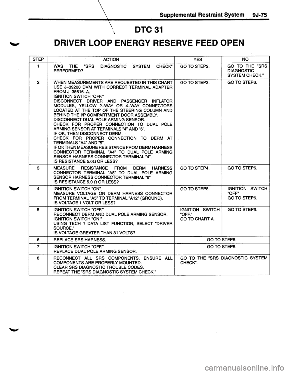
DTC31
DRIVER LOOP ENERGY RESERVE FEED OPEN
STEP ACTION YES NO
1 WAS THE "SRS
DIAGNOSTIC SYSTEM CHECK'' GOTOSTEP2. GO TO THE "SRS
PERFORMED? DIAGNOSTIC
SYSTEM CHECK."
2
WHEN MEASUREMENTS ARE REQUESTED IN THIS CHART GOTOSTEP3. GOTOSTEP6.
USE J-39200 DVM WITH CORRECT TERMINAL ADAPTER FROM J-35616-A.
IGNITION SWITCH "OFF."
DISCONNECT DRIVER AND PASSENGER INFLATOR
MODULES, YELLOW 2-WAY OR 4-WAY CONNECTORS
LOCATED AT THE TOP OF THE STEERING COLUMN AND BEHIND THE 1/P COMPARTMENT DOOR ASSEMBLY. DISCONNECT DUAL POLE ARMING SENSOR.
CHECK FOR PROPER CONNECTION TO DUAL POLE
ARMING SENSOR AT TERMINALS "4" AND "6".
IF OK, THEN DISCONNECT DERM. CHECK
FOR PROPER CONNECTION
TO DERM AT TERMINALS "A4" AND "5".
IF OK
THEN MEASURE RESISTANCE FROM DERM HARNESS
CONNECTOR TERMINAL "A4" TO DUAL POLE ARMING
SENSOR HARNESS CONNECTOR TERMINAL "4". IS RESISTANCE 5.00 OR LESS?
3 MEASURE RESISTANCE FROM DERM HARNESS GOTOSTEP4. GOTOSTEP6.
CONNECTOR TERMINAL "A5" TO DUAL POLE ARMING
SENSOR HARNESS CONNECTOR TERMINAL "6"
IS RESISTANCE 5.0 Q OR LESS?
4 IGNITION SWITCH "ON". GOTOSTEP5. IGNITION SWITCH
MEASURE VOLTAGE ON DERM HARNESS CONNECTOR "OFF"
FROM TERMINAL "A5" TO TERMINAL "A12" (GROUND). GOTO STEPS.
IS VOLTAGE 1 VOLT OR LESS?
5 IGNITION SWITCH "OFF." IGNITION
SWITCH GOTO STEPS.
RECONNECT
DERM AND DUAL POLE ARMING SENSOR. "OFF."
IGNITION SWITCH "ON." GO TO CHART A. USING TECH 1 DATA LIST FUNCTION, SELECT "DRIVER
SOURCE." IS VOLTAGE
GREATER THAN 31 VOLTS?
6 REPLACE SRS HARNESS. GOTOSTEP8.
7 IGNITION SWITCH "OFF." GOTOSTEP8.
REPLACE DUAL POLE ARMING SENSOR.
8 RECONNECT ALL SRS COMPONENTS, ENSURE ALL GO TO THE "SRS DIAGNOSTIC SYSTEM
COMPONENTS
ARE PROPERLY MOUNTED. CHECK".
CLEAR SRS DIAGNOSTIC TROUBLE CODES.
REPEAT THE "SRS DIAGNOSTIC SYSTEM CHECK."
Page 1700 of 1928
9J-76 Supplemental Restraint System
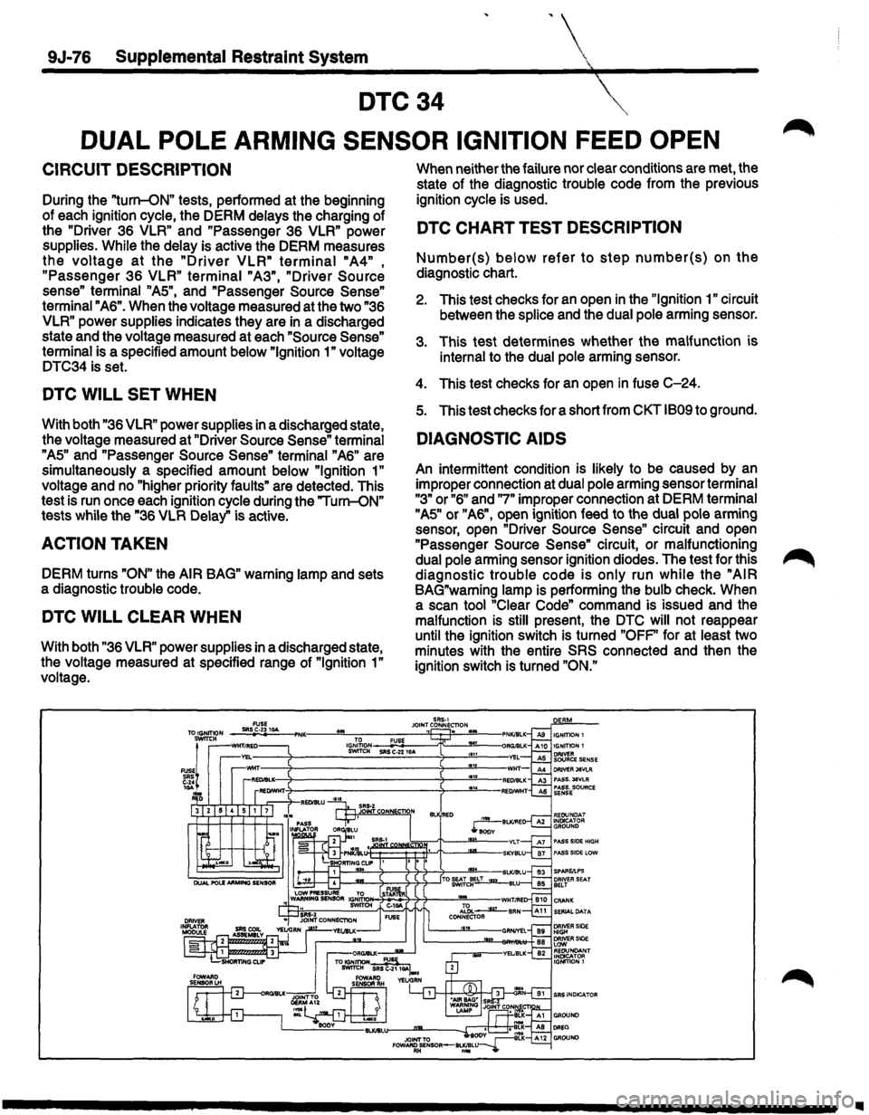
DTC34
DUAL POLE ARMING SENSOR IGNITION FEED OPEN
CIRCUIT DESCRIPTION
During the "turn-ON" tests, performed at the beginning
of each ignition cycle, the DERM delays the charging of
the
"Driver 36 VLR" and "Passenger 36 VLR" power
supplies.
While the delay is active the DERM measures
the voltage at the "Driver VLR" terminal "A4" ,
"Passenger 36 VLR" terminal "A3", "Driver Source
sense" terminal "AS", and "Passenger Source Sense"
terminal "A6". When the voltage measured at the two "36
VLR" power supplies indicates they are in a discharged
state and the voltage measured at each
"Source Sense"
terminal is a specified amount below "Ignition 1" voltage
DTC34 is set.
DTC WILL SET WHEN
With both "36 VLR" power supplies in a discharged state,
the voltage measured at "Driver
Source Sense" terminal
"AS" and "Passenger Source Sense" terminal "A6" are
simultaneously a specified amount below
"Ignition 1"
voltage and no "higher priority faults" are detected. This
test is run once each ignition cycle during the "Turn-ON"
tests while the "36
VLR Delay" is active.
ACTION TAKEN
DERM turns "ON" the AIR BAG" warning lamp and sets
a diagnostic trouble code.
DTC WILL CLEAR WHEN
With both "36 VLR" power supplies in a discharged state,
the voltage measured at specified range of
"Ignition 1"
voltage. When
neither the failure nor clear conditions are met, the
state of the diagnostic trouble code from the previous
ignition cycle is used.
DTC CHART TEST DESCRIPTION
Number(s) below refer to step number(s) on the
diagnostic chart.
2. This test checks for an open in the "Ignition 1" circuit
between the
splice and the dual pole arming sensor.
3. This test determines whether the malfunction is
internal to the dual pole arming sensor.
4. This test checks for an open in fuse C-24.
s. This test checks for a short from CKT 1809 to ground.
DIAGNOSTIC AIDS
An intermittent condition is likely to be caused by an
improper connection at dual pole arming sensor terminal
"3" or "6" and "7" improper connection at DERM terminal
"AS" or "A6", open ignition feed to the dual pole arming
sensor, open "Driver
Source Sense" circuit and open
"Passenger
Source Sense" circuit, or malfunctioning
dual pole arming sensor ignition diodes. The test for this
diagnostic trouble code is only run while the "AIR
BAG"warning lamp is performing the bulb check. When
a scan tool "Clear Code" command is issued and the
malfunction
is still present, the DTC will not reappear
until the ignition switch is turned
"OFP' for at least two
minutes with the entire
SRS connected and then the
ignition switch is turned
"ON."
Ill
Page 1701 of 1928
Supplemental Restraint System 9J-77
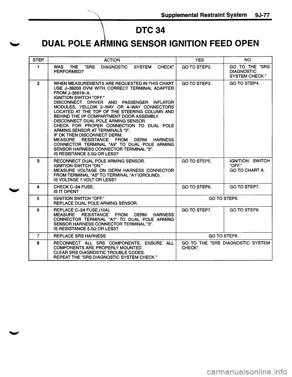
DTC34
'-" DUAL POLE A MING SENSOR IGNITION FEED OPEN
STEP
ACTION YES NO
1 WAS THE "SRS
DIAGNOSTIC SYSTEM CHECK" GOTOSTEP2. GO TO THE "SRS
PERFORMED? DIAGNOSTIC
SYSTEM CHECK."
2 WHEN MEASUREMENTS ARE REQUESTED IN THIS CHART GOTOSTEP3. GOTO STEP4.
USE J-39200 DVM WITH CORRECT TERMINAL ADAPTER FROM J-35616-A. IGNITION SWITCH "OFF."
DISCONNECT DRIVER
AND PASSENGER INFLATOR
MODULES, YELLOW 2-WAY OR 4-WAY CONNECTORS
LOCATED AT THE TOP OF THE STEERING COLUMN AND BEHIND THE 1/P COMPARTMENT DOOR ASSEMBLY.
DISCONNECT DUAL POLE ARMING SENSOR.
CHECK FOR PROPER CONNECTION TO
DUAL POLE
ARMING SENSOR AT TERMINALS "3".
IF OK THEN DISCONNECT DERM.
MEASURE RESISTANCE FROM DERM HARNESS
CONNECTOR TERMINAL "A9" TO DUAL POLE ARMING
SENSOR HARNESS CONNECTOR TERMINAL "3". IS RESISTANCE 5.00 OR LESS?
3 RECONNECT DUAL POLE ARMING SENSOR. GO TO STEPS. IGNITION
SWITCH
IGNITION SWITCH "ON." "OFF."
MEASURE VOLTAGE ON DERM HARNESS
CONNECTOR GO
TO CHART A.
FROM TERMINAL "AS" TO TERMINAL "A 1 "(GROUND).
IS VOLTAGE 1 VOLT OR LESS?
4 CHECK C-24 FUSE. GOTO STEP6. GOTOSTEP7.
IS IT OPEN?
5 IGNITION SWITCH "OFF." GOTOSTEP8.
REPLACE DUAL POLE ARMING SENSOR.
6 REPLACE C-24 FUSE.(10A) GOTOSTEP7. GOTO STEPS.
MEASURE RESISTANCE FROM DERM HARNESS
CONNECTOR TERMINAL "A1" TO DUAL POLE ARMING
SENSOR HARNESS CONNECTOR TERMINAL "3".
IS RESISTANCE
5.00 OR LESS?
7 REPLACE SRS HARNESS GOTOSTEP8.
8 RECONNECT ALL SRS COMPONENTS, ENSURE ALL GO TO THE "SRS DIAGNOSTIC SYSTEM
COMPONENTS
ARE PROPERLY MOUNTED. CHECK".
CLEAR SRS DIAGNOSTIC TROUBLE CODES. REPEAT THE "SRS DIAGNOSTIC SYSTEM CHECK."
Page 1702 of 1928
9J-78 Supplemental Restraint System
DTC35 ~
DISCRIMINATING SENSOR OPEN OR MISSING
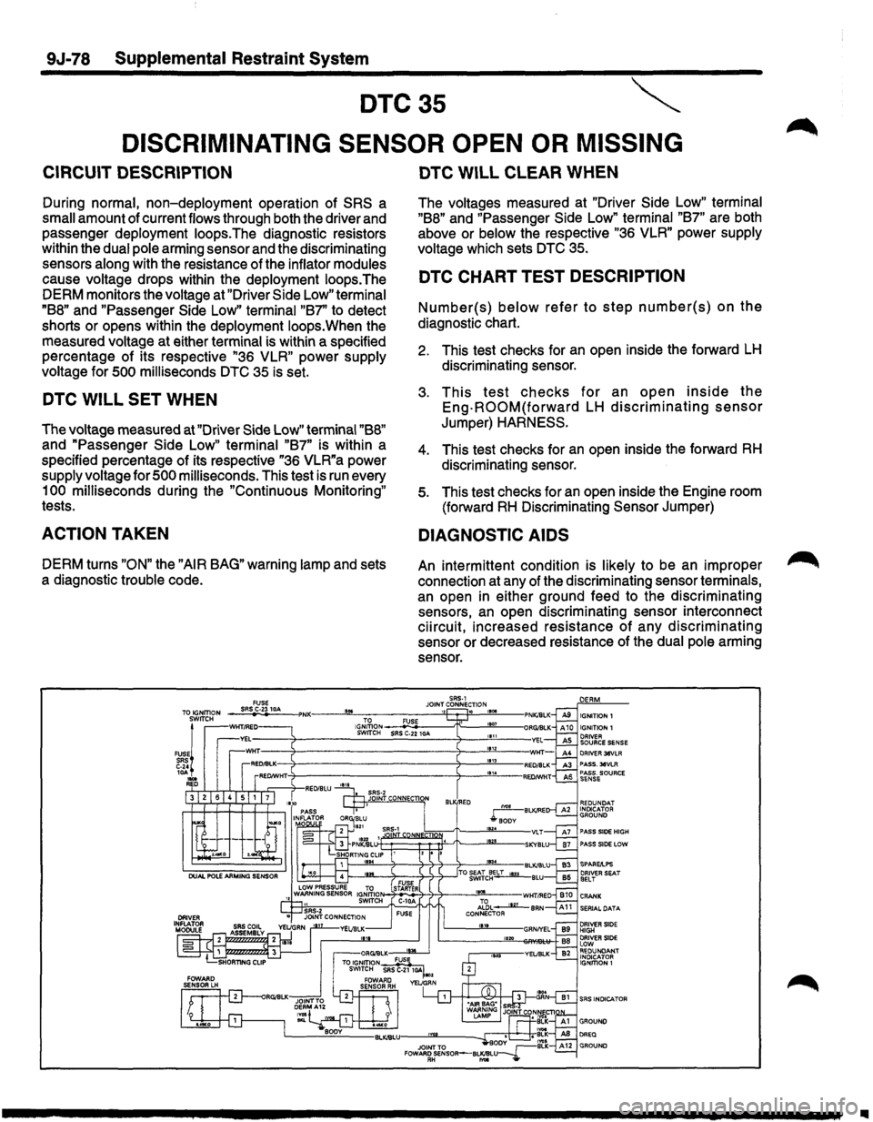
CIRCUIT DESCRIPTION
During normal, non-deployment operation of SRS a
small amount of current flows through both the driver and
passenger deployment loops.The diagnostic resistors
within the dual pole arming sensor and the discriminating
sensors along with the resistance of the inflator modules
cause voltage drops within the deployment loops.The
DERM monitors the voltage at "Driver Side
Low" terminal
"B8" and "Passenger Side Low" terminal "B7' to detect
shorts or opens within the deployment loops.When the
measured voltage at either terminal is within a specified
percentage of its respective
"36 VLR" power supply
voltage for
500 milliseconds DTC 35 is set.
DTC WILL SET WHEN
The voltage measured at "Driver Side Low" terminal "B8"
and "Passenger Side Low" terminal "B7" is within a
specified percentage
of its respective "36 VLR"a power
supply voltage for
500 milliseconds. This test is run every
1
00 milliseconds during the "Continuous Monitoring"
tests.
ACTION TAKEN
DERM turns "ON" the "AIR BAG" warning lamp and sets
a diagnostic trouble code.
...
DTC WILL CLEAR WHEN
The voltages measured at "Driver Side Low" terminal
"B8" and "Passenger Side Low" terminal "B7" are both
above or
below the respective "36 VLR" power supply
voltage which sets
DTC 35.
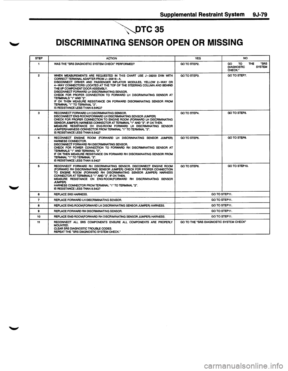
DTC CHART TEST DESCRIPTION
Number(s) below refer to step number(s) on the
diagnostic chart.
2. This test checks for an open inside the forward LH
discriminating sensor.
3. This test checks for an open inside the
Eng-ROOM(forward LH discriminating sensor
Jumper) HARNESS.
4. This test checks for an open inside the forward RH
discriminating sensor.
5. This test checks for an open inside the Engine room
(forward
RH Discriminating Sensor Jumper)
DIAGNOSTIC AIDS
An intermittent condition is likely to be an improper
connection at any of the discriminating sensor terminals,
an open in either ground feed to the discriminating
sensors,
an open discriminating sensor interconnect
ciircuit, increased resistance
of any discriminating
sensor or decreased resistance of the dual pole arming
sensor.
SRS-1 JOINT CONNECTION ,, .
DRIVER 38VLA PASS. 38VLA PASS. SOURCE SENSE
REDUNDAT INDICATOR GROUND
PASS SIDE HIGH
f---""------o~---4--'T--:f----7-------'..,_-BLKJBLU f---.!W...----o~---4--'T--:)--ITO ~~tc~~BLU
N-:1~i7-7?--.J!2!L--wHTI!'ED Al~L __..Jlli__ BAN CONNECTOR 111t
SERIAL DATA
DRIVER SIDE HIGH DRIVER SIDE lOW REDUNDANT INDICATOR IGNffiON 1
..
Page 1703 of 1928
Supplemental Restraint System 9J-79
,~DTC35
DISCRIMINATING SENSOR OPEN OR MISSING
STEP ACTION YES NO
1 WAS THE "SRS DIAGNOSTIC SYSTEM CHECK" PERFORMED? GOTOSTEP2. GO TO THE "SRS DIAGNOSTIC SYSTEM CHECK."
2 WHEN MEASUREMENTS ARE REQUESTED IN THIS CHART USE J-39200 DVM WITH GOTOSTEP3. GOTOSTEP7. CORRECT TERMINAL ADAPTER FROM J-35616-A. DISCONNECT DRIVER AND PASSENGER INFLATOR MODULES, YELLOW 2-WAY OR 4-WAY CONNECTORS LOCATED AT THE TOP OF THE STEERING COLUMN AND BEHIND THE 1/P COMPONENT DOOR ASSEMBLY. DISCONNECT FORWARD LH DISCRIMINATING SENSOR. CHECK FOR PROPER CONNECTION TO FORWARD LH DISCRIMINATING SENSOR AT TERMINALS "1" AND "2". IF OK THEN MEASURE RESISTANCE ON FORWARD DISCRIMINATING SENSOR FROM TERMINAL "1" TO TERMINAL "2". IS RESISTANCE LESS THAN 8.54K.Cl?
3 RECONNECT FORWARD LH DISCRIMINATING SENSOR. GOTOSTEP4. GOTOSTEP8. DISCONNECT ENG·ROOM(FORWARD LH DISCRIMINATING SENSOR JUMPER) CHECK FOR PROPER CONNECTION TO ENGINE ROOM (FORWARD LH DISCRIMINATING SENSOR JUMPER) HARNESS CONNECTOR AT TERMINAL "1" AND "2". IF OK THEN. MEASURE RESISTANCE OH ENG·ROOM FORWARD LH DISCRIMINATING SENSOR JUMPER) HARNESS CONNECTOR FROM TERMINAL "1" TO TERMINAL "2". IS RESISTANCE LESS THAN 8.540?
4
RECONNECT ENGINE ROOM (FORWARD LH DISCRININATING SENSOR JUMPER) GOTOSTEP5. GO TO STEPS. HARNESS CONNECTOR. DISCONNECT FORWARD RH DISCRIMINATING SENSOR. CHECK FOR POWER CONNECTION TO FORWARD RH DISCRIMINATING SENSOR AT TERMINALS "1" AND TERMINAL "2". IF OK THEN MEASURE RESISTANCE ON FORWARD RH DISCRIMINATING SENSOR FROM TERMNAL "1" TO TERMINAL "2". IS RESISTANCE LESS THAN 8.540?
5 RECONNECT FORWARD RH DISCRIMINATING SENSOR. DISCONNECT ENGINE ROOM GOTOSTEP6. GO TO STEP10. (FORWARD RH DISCRIMINATING SENSOR JUMPER) CHECK FOR PROPER CONNECTION TO ENGINE ROOM (FORWARD RH DISCRIMINATING SENSOR JUMPER) HARNESS CONNECTOR AT TERMINALS "1" AND "2".1F OK THEN. MEASURE RESISTANCE ON ENG·ROOM(FORWARD RH DISCRIMINATING SENSOR JUMPER) HARNESS CONNECTOR FROM TERMINAL "1" TO TERMINAL "2". IS RESISTANCE LESS THAN 8.540?
6 REPLACE SRS HARNESS. GOTOSTEP11.
7 REPLACE FORWARD LH DISCRIMINATING SENSOR. GOTOSTEP11.
8 REPLACE ENG.ROOM(FORWARD LH DISCRIMINATING SENSOR JUMPER) HARNESS. GOTOSTEP11.
9 REPLACE FORWARD RH DISCRIMINATING SENSOR. GOTOSTEP11.
10 REPLACE ENG·ROOM(FORWARD RH DISCRIMINATING SENSOR JUMPER) HARNESS. GOTOSTEP11.
11 RECONNECT ALL SRS COMPONENTS ENSURE ALL COMPONENTS ARE PROPERLY GO TO THE "SRS DIAGNOSTIC SYSTEM CHECK" MOUNTED. CLEAR SRS DIAGNOSTIC TROUBLE CODES. REPEAT THE "SRS DIAGNOSTIC SYSTEM CHECK."
Page 1704 of 1928
9J-80 Supplemental Restraint System
DTC36
PASSENGER LOOP ENERGY RESERVE FEED OPEN
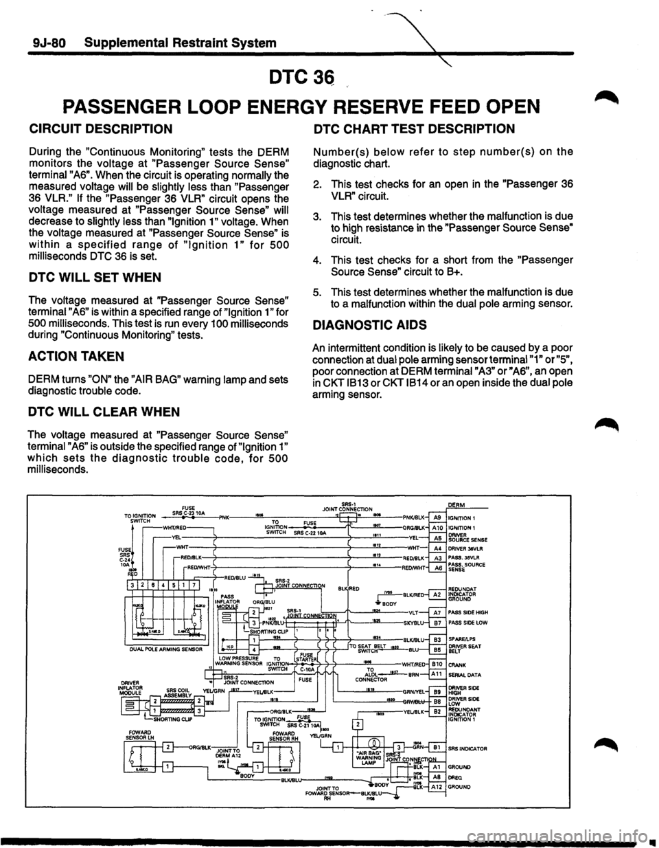
CIRCUIT DESCRIPTION
During the "Continuous Monitoring" tests the DERM
monitors the voltage at
"Passenger Source Sense"
terminal "AS". When the circuit is operating normally the
measured voltage
will be slightly less than "Passenger
3S VLR." If the "Passenger 3S VLR" circuit opens the
voltage measured at
"Passenger Source Sense" will
decrease to slightly less than "Ignition 1" voltage. When
the voltage measured at
"Passenger Source Sense" is
within a specified range of "Ignition 1" for 500
milliseconds DTC 3S is set.
DTC WILL SET WHEN
The voltage measured at "Passenger Source Sense"
terminal "AS" is within a specified range of "Ignition 1" for
500 milliseconds. This test is run every 100 milliseconds
during "Continuous Monitoring" tests.
ACTION TAKEN
DERM turns "ON" the "AIR BAG" warning lamp and sets
diagnostic trouble code.
DTC WILL CLEAR WHEN
The voltage measured at "Passenger Source Sense"
terminal "AS" is outside the specified range of "Ignition 1"
which sets the diagnostic trouble code, for 500
milliseconds.
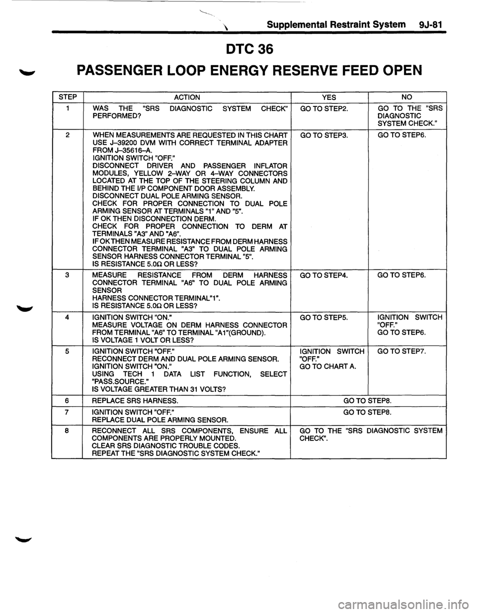
DTC CHART TEST DESCRIPTION
Number(s) below refer to step number(s) on the
diagnostic chart.
2. This test checks for an open in the "Passenger 3S
VLR" circuit.
3. This test determines whether the malfunction is due
to high resistance
in the "Passenger Source Sense"
circuit.
4. This test checks for a short from the
"Passenger
Source Sense"
circuit to B+.
5. This test determines whether the malfunction is due
to a malfunction within the dual pole arming sensor.
DIAGNOSTIC AIDS
An intermittent condition is likely to be caused by a poor
connection at dual pole arming sensor terminal
"1" or "5",
poor connection at DERM terminal "A3" or" AS", an open
in CKT 1813 or CKT 1814 or an open inside the dual pole
arming sensor.
SAS·l
JOINT CONNECTION ,.,. " IGNITION 1
DRIVER 38VLR PASS.38VLR PASS. SOURCE SENSE
PASS SIDE HIGH PASS SIDE LOW
SERIAL DATA
SRS INDICATOR
..
Page 1705 of 1928
Supplemental Restraint System 9J-81
DTC36
'-" PASSENGER LOOP ENERGY RESERVE FEED OPEN
STEP
ACTION YES NO
1 WAS THE "SRS
DIAGNOSTIC
SYSTEM CHECK" GOTOSTEP2. GO TO THE "SRS PERFORMED? DIAGNOSTIC
SYSTEM CHECK."
2 WHEN
MEASUREMENTS ARE REQUESTED IN THIS CHART GOTOSTEP3. GOTOSTEP6.
USE J-39200 DVM WITH CORRECT TERMINAL ADAPTER FROM J-35616-A.
IGNITION SWITCH "OFF."
DISCONNECT DRIVER
AND PASSENGER INFLATOR
MODULES, YELLOW 2-WAY OR 4-WAY CONNECTORS LOCATED AT THE TOP OF THE STEERING COLUMN AND BEHIND THE 1/P COMPONENT DOOR ASSEMBLY.
DISCONNECT DUAL POLE ARMING SENSOR.
CHECK FOR PROPER CONNECTION TO DUAL POLE
ARMING SENSOR AT TERMINALS "1" AND "5".
IF OK THEN DISCONNECTION DERM.
CHECK FOR PROPER CONNECTION TO DERM AT TERMINALS "A3" AND "A6".
IF OK THEN MEASURE RESISTANCE FROM DERM HARNESS
CONNECTOR TERMINAL "A3" TO DUAL POLE ARMING
SENSOR HARNESS CONNECTOR TERMINAL "5".
IS RESISTANCE 5.00. OR LESS?
3 MEASURE
RESISTANCE
FROM DERM HARNESS GOTOSTEP4. GOTO STEP6.
CONNECTOR TERMINAL "A6" TO
DUAL POLE ARMING
SENSOR HARNESS CONNECTOR TERMINAL"1".
IS RESISTANCE 5.00. OR LESS?
4 IGNITION SWITCH "ON." GOTOSTEP5. IGNITION
SWITCH
MEASURE VOLTAGE ON
DERM HARNESS CONNECTOR "OFF."
FROM TERMINAL "A6" TO TERMINAL "A1"{GROUND). GOTOSTEP6.
IS VOLTAGE 1 VOLT OR LESS?
5 IGNITION SWITCH "OFF." IGNITION SWITCH GOTOSTEP7.
RECONNECT DERM AND DUAL POLE ARMING SENSOR.
"OFF."
IGNITION SWITCH "ON." GO TO CHART A. USING TECH 1 DATA LIST FUNCTION, SELECT
"PASS.SOURCE."
IS
VOLTAGE GREATER THAN 31 VOLTS?
6
REPLACE SRS HARNESS. GOTOSTEP8.
7 IGNITION SWITCH "OFF." GOTOSTEP8. REPLACE DUAL POLE ARMING SENSOR.
8
RECONNECT ALL SRS COMPONENTS, ENSURE ALL GO TO THE "SRS DIAGNOSTIC SYSTEM
COMPONENTS ARE PROPERLY MOUNTED. CHECK". CLEAR SRS DIAGNOSTIC TROUBLE CODES. REPEAT THE "SRS DIAGNOSTIC SYSTEM CHECK."
Page 1706 of 1928
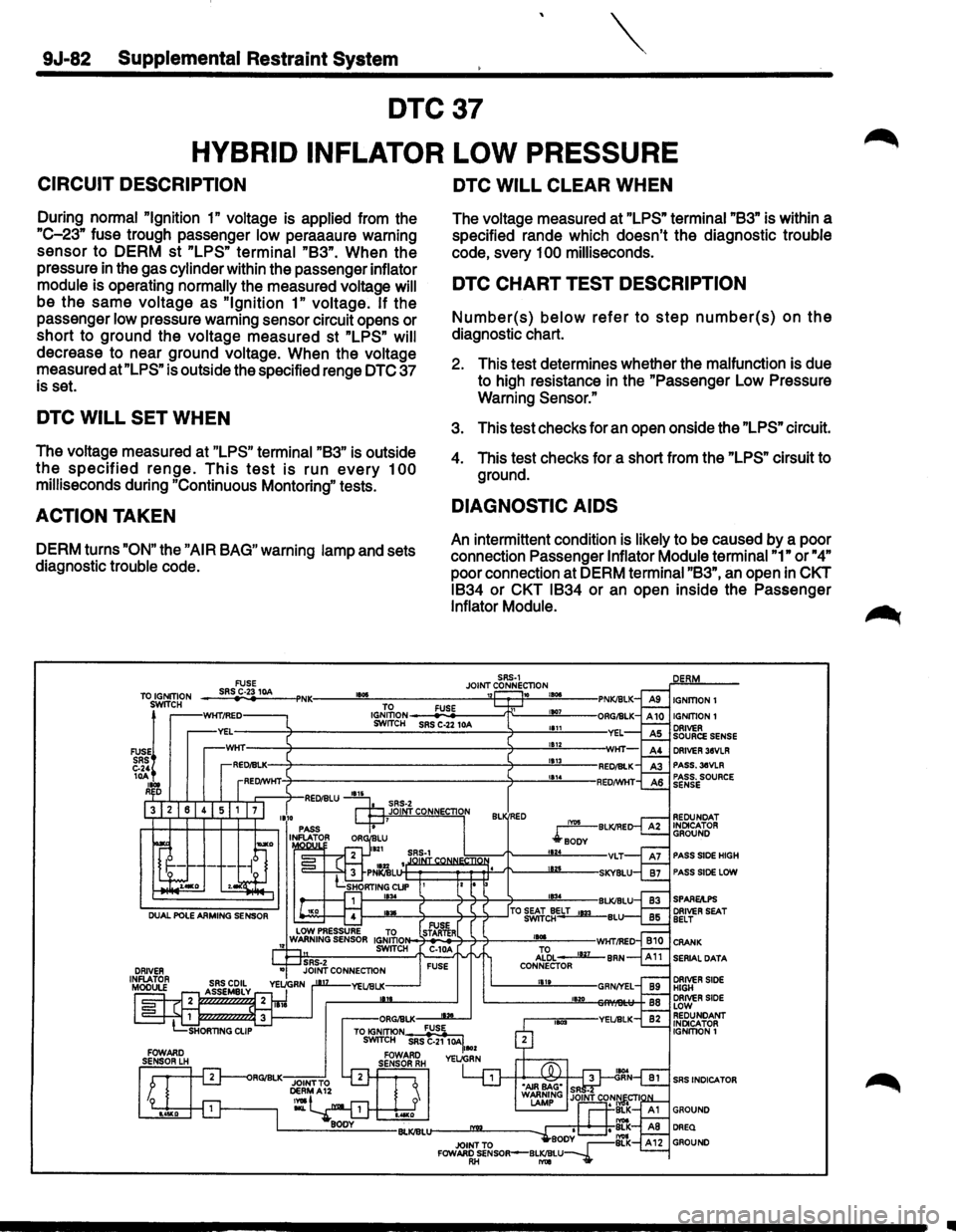
9J·82 Supplemental Restraint System
DTC37
HYBRID INFLATOR LOW PRESSURE
CIRCUIT DESCRIPTION
During normal "Ignition 1" voltage is applied from the
"C-23" fuse trough passenger low peraaaure warning
sensor to DERM st
"LPS" terminal "83". When the
pressure in the gas cylinder within the passenger inflator
module is operating normally the measured voltage will
be the same voltage as "Ignition 1" voltage. If the
passenger
low pressure warning sensor circuit opens or
short to ground the voltage measured st
"LPS" will
decrease to near ground voltage. When the voltage
measured
at"LPS" is outside the specified renge DTC 37
is set.
DTC WILL SET WHEN
The voltage measured at "LPS" terminal "83" is outside
the specified renge. This test is run every 100
milliseconds during "Continuous Montoring" tests.
ACTION TAKEN
DERM turns "ON" the "AIR BAG" warning lamp and sets
diagnostic trouble code.
DTC WILL CLEAR WHEN
The voltage measured at "LPS" terminal "83" is within a
specified rande which doesn't the diagnostic trouble
code, svery
100 milliseconds.
DTC CHART TEST DESCRIPTION
Number(s) below refer to step number(s) on the
diagnostic chart.
2. This test determines whether the malfunction is due
to high resistance
in the "Passenger Low Pressure
Warning
Sensor."
3. This test checks for an open onside the "LPS" circuit.
4. This test checks for a short from the "LPS" cirsuit to
ground.
DIAGNOSTIC AIDS
An intermittent condition is likely to be caused by a poor
connection Passenger
Inflator Module terminal "1" or "4"
poor connection at DERM terminal "83", an open in CKT
1834 or CKT 1834 or an open inside the Passenger
Inflator Module.
SRS-1 JOINT CONNECTION 10 , ... IGNITION!
IGNITION 1 ORIVER SOURCE SENSE DRIVER 38VLR PASS.3eVLR PASS. SOURCE SENSE
REDUNDAT INDICATOR GROUND
PASS SIDE HIGH
PASS SIDE LOW
SPARE/I.PS DRIVER SEAT BELT
SERIAL DATA
DRIVER SIDE HIGH DRIVER SIDE LOW REDUNDANT INDICATOR IGNITION!
SRS INDICATOR
..