sensor ISUZU TROOPER 1995 Workshop Manual
[x] Cancel search | Manufacturer: ISUZU, Model Year: 1995, Model line: TROOPER, Model: ISUZU TROOPER 1995Pages: 1928
Page 1742 of 1928
9J-118 Supplemental Restraint System
attachments
- Driver seat and belt
- Passenger seat and belt
- Dual Pole Arming
Sensor
-Discriminating Sensors
-DERM
The sensor replacement policy specifies mandatory
replacement of the sensors, after crash involving
AIR
BAG deployment. If AIR BAG has not been deployd,
Replace the sensors
in the area of accident damage only.
The
"area of accident damage" is defined as that area of
the vehicle which is crushed, bent ,or damaged in other
ways. An example might be a front-end collision
in which
the forward portions of the vehicle have contacted
another vehicle, tree, guardrail,etc.
In this example,
1)
If AIR BAG has deployed, All Sensor should be
replaced.
2)
If AIR BAG has not deployed, replace the sensors
in the area of accident damage only.
sensor(s) on the radiator tie bar would require
replacement, since that portion of the vehicle was
damaged in the accident. The Dual Pole Arming Sensor
would not require mandatory replacement. Of course, if
the DERM sets a code and the diagnostic chart leads to
a faulty sensor that was not in the area of accident
damage, that sensor should also be replaced.Sensors
in
the area of accident damage should be replaced even if
those sensors do not appear to be damaged. Do not
attempt to determine whether a sensor is
OK-ALWAYS
replace it if it is in the area of accident damage.Aiso, if a
sensor is
in an area of accident damage,but the SRS has
NOT been deployed,replace the sensor.The sensor
bracket may be slightly bent,wiring may be
damaged, etc., and the sensor might not work properly
in
another collision. Again, do not attempt to determine
whether a sensor is
OK --ALWAYS replace it if it is in
the area of accident damage. Also,
inspect
SRS coil assembly wiring and steering
wheel for any signs of scorching, melting, or damage due
to excessive heat.
If the coil assembly wire or steering ~
wheel is damaged, replace them. The steering column
and wheel must be dimensionally checked to determine
if they are damaged. Refer to
in this Section 3 of this
manual.
Never use
SRS parts from another vehicle. This does not
include remanufactured parts purchased from an
authorized
ISUZU Dealer; they may be used for SRS
repairs.
Do not attempt to repair the forward discriminating
sensors ,the dual pole arming senor, the DERM, the
SRS
coil assembly, the inflator modules, the steering wheel, or
the steering column. Service of these items is
replacement only.
Verify replacement part numbers.
CAUTION: PROPER OPERATION OF THE
SENSORS AND SUPPLEMENTAL RESTRAINT
SYSTEM(SRS)REQUIRES THAT ANY REPAIRS TO
THE VEHICLE STRUCTURE RETURN IT TO ITS
ORIGINAL PRODUCTION CONFIGURATION.
II
Page 1743 of 1928
Supplemental Restraint System 9J-119
DIAGNOSTIC ENERGY RESERVE ,MODULE
WARNING: DURING SERVICE PROCEDURES, BE VERY CAREFUL WHEN HANDLING A SENSOR. NEVER
STRIKE OR
JAR A SENSOR. UNDER SOME CIRCUMSTANCES, IT COULD CAUSE DEPLOYMENT AND
RESULT IN PERSONAL INJURY OR IMPROPER OPERATION OF THE SUPPLEMENTAL RESTRAINT SYSTEM(
SRS
). ALL SENSOR AND MOUNTING BRACKET BOLTS MUST BE CAREFULLY TORQUED TO ASSURE
PROPER OPERATION. NEVER POWER UP THE SRS WHEN ANY SENSOR IS NOT RIGIDLY ATTACHED TO
VEHICLE, SINCE
THE SENSOR COULD BE ACTIVATED WHEN NOT ATTACHED AND COULD RESULT IN
DEPLOYMENT.
WARNING: PROPER OPERATION OF THE SENSORS AND SUPPLEMENTAL RESTRAINT SYSTEM( SRS)
REQUIRES
THAT ANY REPAIRS TO THE VEHICLE STRUCTURE RETURN IT TO ITS ORIGINAL PRODUCTION
CONFIGURATION.
DEPLOYMENT (CURRENT CODE 51 )OR ANY VISIBLE DAMAGE TO SENSOR AND/OR
THEIR MOUNTING BRACKETS REQUIRES REPLACEMENT, NOT REPAI~. PROPER OPERATION OF A
SENSOR ALSO REQUIRES THAT SENSOR BE RIGIDLY BOLTED TO THE VEHICLE STRUCTURE.THE ARROW
ON THE SENSOR MUST BE POINTING TOWARD THE FRONT OF THE VEHICLE. FAILURE TO OBSERVE
THESE PRECAUTIONS CAN RESULT IN IMPROPER SRS OPERATION AND POSSIBLE LACK OF
SUPPLEMENTAL RESTRAINT PROTECTION FOR THE DRIVER AND PASSENGER DURING AN ACCIDENT
IMPACT.
All
sensors are specifically calibrated and are keyed to the sensor location and SRS wiring harness. Caution should
be used to ensure proper location of the sensors. The keying of the sensor to their locations and wiring harness
connectors should never be modified in the filed.
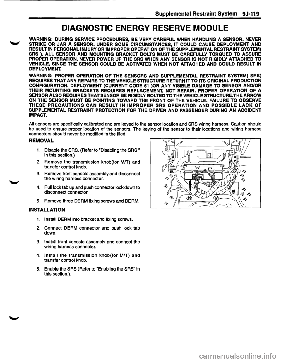
REMOVAL
1. Disable the SRS. (Refer to "Disabling the SRS "
in this section.)
2. Remove the transmission knob(for MIT) and
transfer control knob.
3. Remove front console assembly and disconnect
the wiring harness connector.
4. Pull lock tab up and push connector lock down to
disconnect connector.
5. Remove three DERM fixing screws and DERM. •d ...........
INSTALLATION
1. Install DERM into bracket and fixing screws.
2. Connect DERM connector and push lock tab
down.
3. Install front console assembly and connect the
wiring harness connector.
4. Install the transmission knob(for MIT) and
transfer control knob.
5. Enable the SRS (Refer to "Enabling the SRS" in
this section.).
Page 1744 of 1928
9J-120 Supplemental Restraint System
DISCRIMINATING SENSOR -FORWARD SENSOR LH
WARNING: DURING SERVICE PROCEDURES, BE VERY CAREFUL WHEN HANDLING A SENSOR. NEVER ~
STRIKE OR JAR A SENSOR. UNDER SOME CIRCUMSTANCES, IT COULD CAUSE DEPLOYMENT AND
RESULT IN PERSONAL INJURY OR IMPROPER OPERATION OF THE SUPPLEMENTAL RESTRAINT SYSTEM(
SRS
). ALL SENSOR AND MOUNTING BRACKET BOLTS MUST BE CAREFULLY TORQUED TO ASSURE
PROPER OPERATION. NEVER POWER UP THE SRS WHEN ANY SENSOR IS NOT RIGIDLY ATTACHED TO
VEHICLE, SINCE
THE SENSOR COULD BE ACTIVATED WHEN NOT ATTACHED AND COULD RESULT IN
DEPLOYMENT.
WARNING: PROPER OPERATION OF THE SENSORS AND SUPPLEMENTAL RESTRAINT SYSTEM( SRS)
REQUIRES
THAT ANY REPAIRS TO THE VEHICLE STRUCTURE RETURN IT TO ITS ORIGINAL PRODUCTION
CONFIGURATION.
DEPLOYMENT (CURRENT CODE 51 )OR ANY VISIBLE DAMAGE TO SENSOR AND/OR
THEIR MOUNTING BRACKETS REQUIRES REPLACEMENT, NOT REPAIR. PROPER OPERATION OF A
SENSOR ALSO REQUIRES THAT SENSOR BE RIGIDLY BOLTED TO THE VEHICLE STRUCTURE. THE ARROW
ON
THE SENSOR MUST BE POINTING TOWARD THE FRONT OF THE VEHICLE. FAILURE TO OBSERVE
THESE PRECAUTIONS CAN RESULT IN IMPROPER SRS OPERATION AND POSSIBLE LACK OF
SUPPLEMENTAL RESTRAINT PROTECTION FOR THE DRIVER AND PASSENGER DURING AN ACCIDENT
IMPACT.
All
sensors are specifically calibrated and are keyed to the sensor location and SRS wiring harness. Caution should
be used to ensure proper location of the sensors. The keying of the sensor to their locations and wiring harness
connectors
should never be modified in the filed.
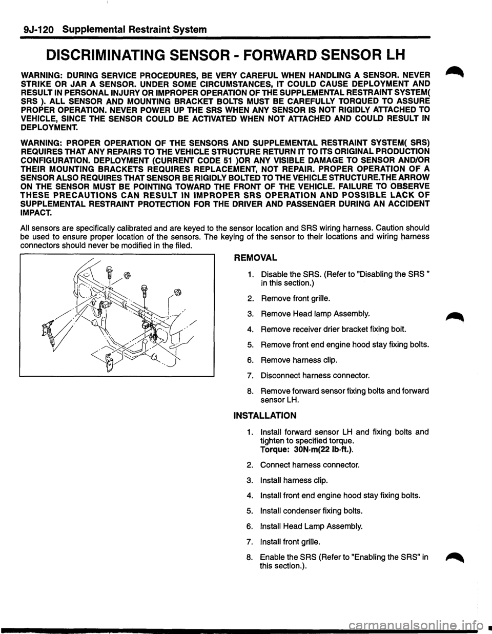
REMOVAL
1. Disable the SRS. (Refer to "Disabling the SRS "
in this section.)
2. Remove front grille.
3. Remove Head lamp Assembly.
4. Remove receiver drier bracket fixing bolt.
5. Remove front end engine hood stay fixing bolts.
6. Remove harness clip.
7. Disconnect harness connector.
8. Remove forward sensor fixing bolts and forward
sensor
LH.
INSTALLATION
1. Install forward sensor LH and fixing bolts and
tighten to specified torque.
Torque:
30N·m(221b·ft.).
2. Connect harness connector.
3. Install harness clip.
4. Install front end engine hood stay fixing bolts.
5. Install condenser fixing bolts.
6. Install Head Lamp Assembly.
7. Install front grille.
8. Enable the SRS (Refer to "Enabling the SRS" in
this section.). ~
•
Page 1745 of 1928
Supplemental Restraint System 9J-121
DISCRIMINATING SENSOR -FORWARD SENSOR RH
WARNING: DURING SERVICE PROCEDURES, BE VERY CAREFUL WHEN HANDLING A SENSOR. NEVER
STRIKE OR JAR A SENSOR. UNDER SOME CIRCUMSTANCES, IT COULD CAUSE DEPLOYMENT AND
RESULT IN PERSONAL INJURY OR IMPROPER OPERATION OF THE SUPPLEMENTAL RESTRAINT SYSTEM(
SRS ). ALL SENSOR AND MOUNTING BRACKET BOLTS MUST BE CAREIFULLY TORQUED TO ASSURE
PROPER OPERATION. NEVER POWER UP
THE SRS WHEN ANY SENSOR IS NOT RIGIDLY ATTACHED TO
VEHICLE, SINCE
THE SENSOR COULD BE ACTIVATED WHEN NOT ATTACHED AND COULD RESULT IN
DEPLOYMENT.
WARNING: PROPER OPERATION
OF THE SENSORS AND SUPPLEMENTAL RESTRAINT SYSTEM( SRS)
REQUIRES
THAT ANY REPAIRS TO THE VEHICLE STRUCTURE RETURN IT TO ITS ORIGINAL PRODUCTION
CONFIGURATION. DEPLOYMENT (CURRENT CODE
51 )OR ANY VISIBLE DAMAGE TO SENSOR AND/OR
THEIR
MOUNTING BRACKETS REQUIRES REPLACEMENT, NOT REPAIR. PROPER OPERATION OF A
SENSOR ALSO REQUIRES THAT SENSOR BE RIGIDLY BOLTED TO THE VEHICLE STRUCTURE. THE ARROW
ON
THE SENSOR MUST BE POINTING TOWARD THE FRONT OF THE VEHICLE. FAILURE TO OBSERVE
THESE PRECAUTIONS CAN RESULT IN IMPROPER SRS OPERATION AND POSSIBLE LACK OF
SUPPLEMENTAL RESTRAINT PROTECTION FOR THE DRIVER AND PASSEMGER DURING AN ACCIDENT
IMPACT.
All
sensors are specifically calibrated and are keyed to the sensor location and SRS wiring harness. Caution should
be used to ensure proper location of the sensors. The keying of the sensor to their locations and wiring harness
connectors
should never be modified in the filed.
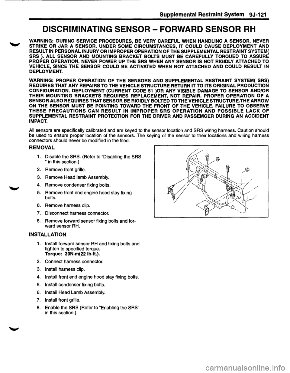
REMOVAL
1. Disable the SRS. (Refer to "Disabling the SRS
"
in this section.)
2. Remove front grille.
3. Remove Head lamb Assembly.
4. Remove condenser fixing bolts.
5. Remove front end engine hood stay fixing
bolts.
6. Remove harness clip.
7. Disconnect harness connector.
8. Remove forward sensor fixing bolts and for
ward sensor RH.
INSTALLATION
1. Install forward sensor RH and fixing bolts and
tighten to specified torque.
Torque: 30N·m{22 lb·ft.).
2. Connect harness connector.
3. Install harness clip.
4. Install front end engine hood stay fixing bolts.
5. Install condenser fixing bolts.
6. Install Head Lamb Assembly.
7. Install front grille.
8. Enable the SRS (Refer to "Enabling the SRS"
in this section.).
Page 1746 of 1928
9J-122 Supplemental Restraint System
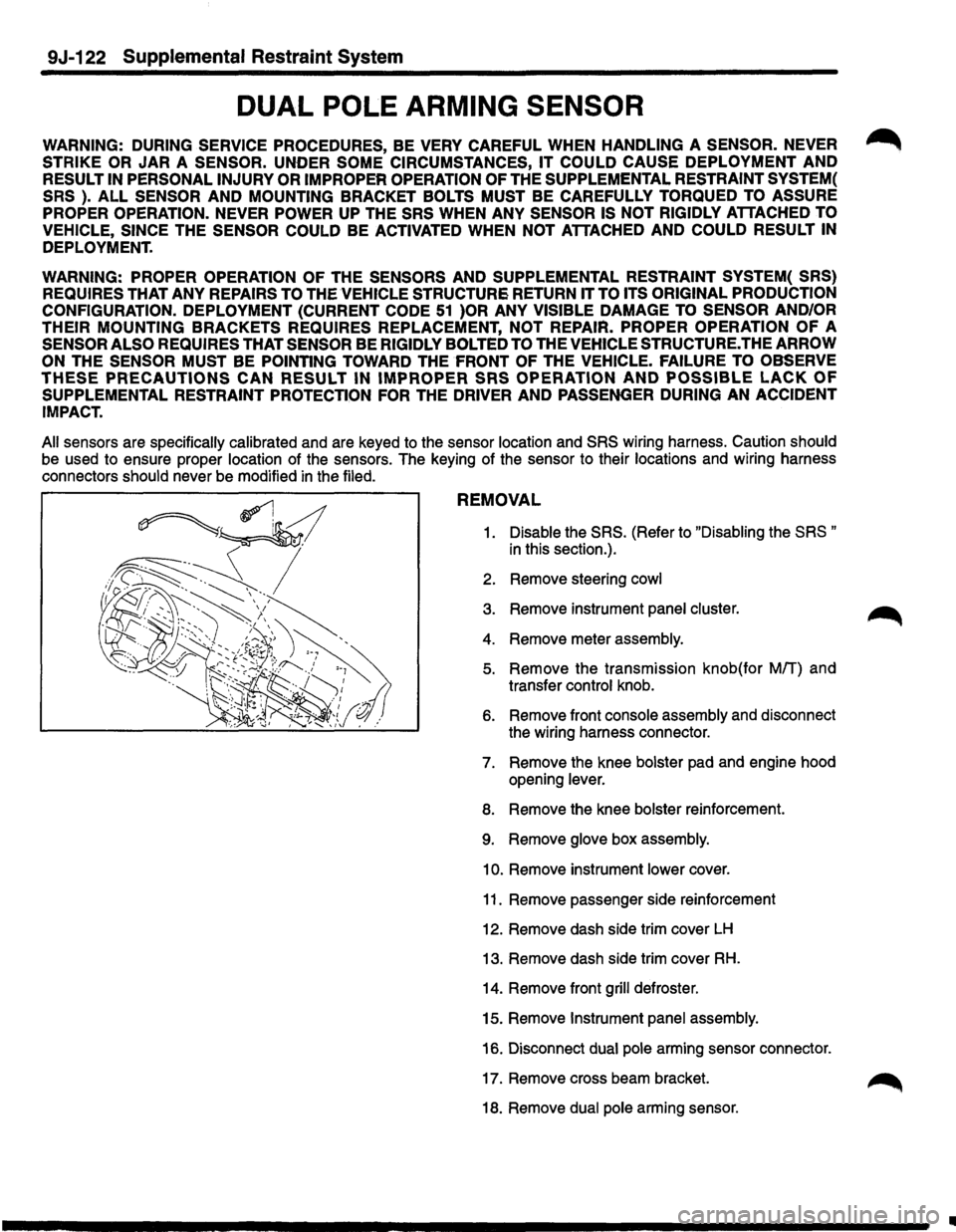
DUAL POLE ARMING SENSOR
WARNING: DURING SERVICE PROCEDURES, BE VERY CAREFUL WHEN HANDLING A SENSOR. NEVER ~
STRIKE OR JAR A SENSOR. UNDER SOME CIRCUMSTANCES, IT COULD CAUSE DEPLOYMENT AND
RESULT IN PERSONAL INJURY OR IMPROPER OPERATION OF THE SUPPLEMENTAL RESTRAINT SYSTEM(
SRS
). ALL SENSOR AND MOUNTING BRACKET BOLTS MUST BE CAREFULLY TORQUED TO ASSURE
PROPER OPERATION. NEVER POWER
UP THE SRS WHEN ANY SENSOR IS NOT RIGIDLY ATTACHED TO
VEHICLE, SINCE
THE SENSOR COULD BE ACTIVATED WHEN NOT ATTACHED AND COULD RESULT IN
DEPLOYMENT.
WARNING: PROPER OPERATION OF THE SENSORS AND SUPPLEMENTAL RESTRAINT SYSTEM( SRS)
REQUIRES
THAT ANY REPAIRS TO THE VEHICLE STRUCTURE RETURN IT TO ITS ORIGINAL PRODUCTION
CONFIGURATION.
DEPLOYMENT (CURRENT CODE 51 )OR ANY VISIBLE DAMAGE TO SENSOR AND/OR
THEIR MOUNTING
BRACKETS REQUIRES REPLACEMENT, NOT REPAIR. PROPER OPERATION OF A
SENSOR ALSO REQUIRES THAT SENSOR BE RIGIDLY BOLTED TO THE VEHICLE STRUCTURE. THE ARROW
ON
THE SENSOR MUST BE POINTING TOWARD THE FRONT OF THE VEHICLE. FAILURE TO OBSERVE
THESE PRECAUTIONS CAN RESULT IN IMPROPER SRS OPERATION AND POSSIBLE LACK OF
SUPPLEMENTAL RESTRAINT PROTECTION FOR THE DRIVER AND PASSENGER DURING AN ACCIDENT
IMPACT.
All
sensors are specifically calibrated and are keyed to the sensor location and SRS wiring harness. Caution should
be used to ensure proper location of the sensors. The keying of the sensor to their locations and wiring harness
connectors should never be modified
in the filed.
REMOVAL
1. Disable the SRS. (Refer to "Disabling the SRS "
in this section.).
2. Remove steering
cowl
3. Remove instrument panel cluster. ~
4. Remove meter assembly.
5. Remove the transmission knob(for Mff) and
transfer control knob.
6. Remove front console assembly and disconnect
the wiring harness connector.
7. Remove the knee bolster pad and engine hood
opening lever.
8. Remove the knee bolster reinforcement.
9. Remove glove box assembly.
10. Remove instrument lower cover.
11. Remove passenger side reinforcement
12. Remove dash side trim cover
LH
13. Remove dash side trim cover RH.
14. Remove front grill defroster.
15. Remove
Instrument panel assembly.
16. Disconnect
dual pole arming sensor connector.
17. Remove cross beam bracket.
18. Remove
dual pole arming sensor.
II
Page 1747 of 1928
INSTALLATION
1. Install dual pole arming sensor and tighten to
specified torque.
Torque: 26N·m(19 lb·ft.).
2. Install cross beam bracket.
3. Connect dual pole arming sensor connector.
4. Install instrument panel assembly.
5. Install front grill defroster.
6. Install dash side trim cover RH.
7. Install dash side trim cover LH.
8.
Install passenger side reinforcement
9. Install instrument lower cover.
1
0. Install glove box assembly.
11. Install the knee bolster reinforcement.
12.
Install the knee bolster pad and engine hood
opening
lever.
13. Install front console assembly and connect the
wiring harness connector.
14.
Install the transmission knob(for M/T) and
transfer control knob.
15.
Install meter assembly.
16. Install instrument panel cluster.
17. Install steering cowl
18. Enable the SRS (Refer to "Enabling the SRS" in
this section.).
Supplemental :Restraint System 9J-123
Page 1757 of 1928
Supplemental Restraint System 9J-133
SPECIFICATION
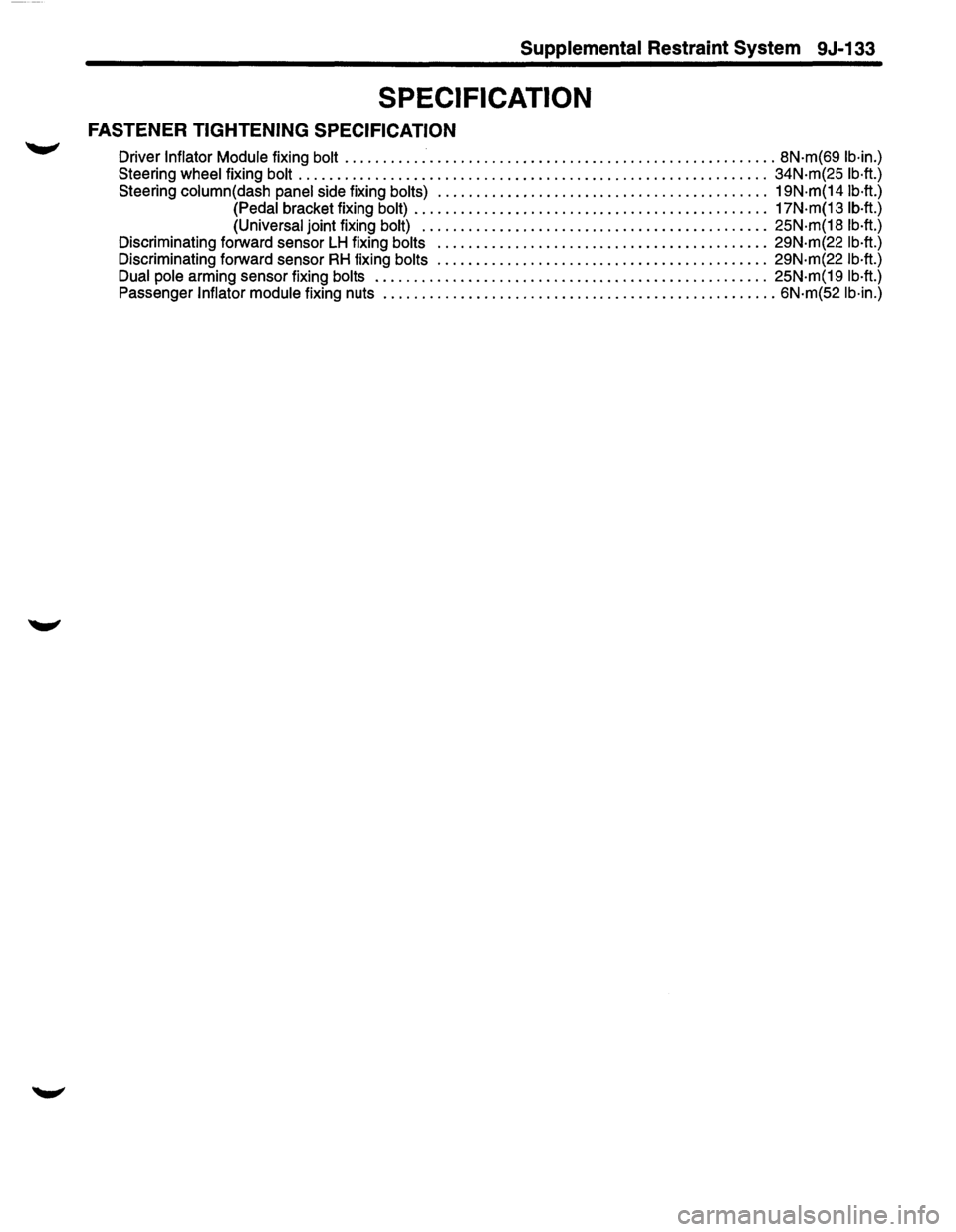
FASTENER TIGHTENING SPECIFICATION
Driver Inflator Module fixing bolt ........................................................ 8N·m(69 lb·in.)
Steering wheel fixing bolt ............................................................. 34N·m(25 lb·ft.)
Steering column(dash panel side fixing bolts) ........................................... 19N·m(14 lb·ft.)
(Pedal bracket fixing bolt) .............................................. 17N·m(13 lb·ft.)
(Universal joint fixing bolt) ............................................. 25N·m(18 lb·ft.)
Discriminating forward sensor LH fixing bolts ........................................... 29N·m(22 lb·ft.)
Discriminating forward sensor RH fixing bolts ........................................... 29N·m(22 lb·ft.)
Dual pole
arming sensor fixing bolts ................................................... 25N·m(19 lb·ft.)
Passenger Inflator module fixing nuts ................................................... 6N·m(52 lb·in.)
Page 1788 of 1928
10-30 BODY
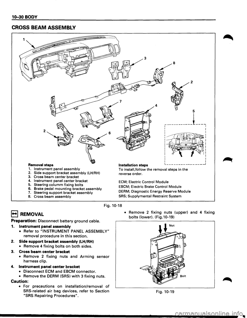
CROSS BEAM ASSEMBLY
2 6
Removal steps 1. Instrument panel assembly 2. Side support bracket assembly (LH/RH)
3. Cross beam center bracket 4. Instrument panel center bracket 5. Steering columm fixing bolts
6. Brake pedal mounting bracket assembly 7. Steering support bracket assembly 8. Cross beam assembly
3
4
Installation steps
8 2
5
, -----------L_l
I I
I
I I
~~~~~®~! II I I I I !._ ___ ---------___ _J
To install, follow the removal steps in the
reverse order.
ECM; Electric Control Module
EBCM; Electric Brake Control Module
DERM; Diagnostic Energy Reserve Module
SRS; Supplymental Restraint System
Fig. 10-18
E) REMOVAL
Preparation: Disconnect battery ground cable.
1. Instrument panel assembly
• Refer to "INSTRUMENT PANEL ASSEMBLY"
removal procedure in this section.
2.
Side support bracket assembly (LH/RH)
• Remove 4 fixing bolts on both sides.
3. Cross beam
center bracket
• Remove 2 fixing nuts and Arming sensor
harness clip.
4. Instrument panel center bracket
• Disconnect ECM and EBCM connector.
• Remove the DERM (SRS) with 3 fixing nuts.
Caution:
• For precautions on installation/removal of
SRS-related air bag devices, refer to Section
"SRS Repairing Procedures". •
Remove
2 fixing nuts (upper) and 4 fixing
bolts (lower). (Fig.10-19)
Fig. 10-19