compression ratio ISUZU TROOPER 1995 Workshop Manual
[x] Cancel search | Manufacturer: ISUZU, Model Year: 1995, Model line: TROOPER, Model: ISUZU TROOPER 1995Pages: 1928
Page 57 of 1928
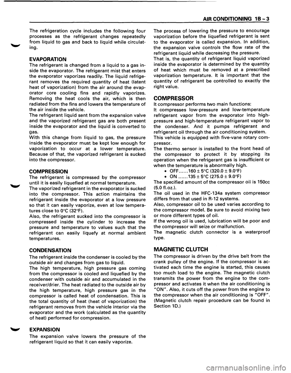
The refrigeration cycle includes the following four
processes as the refrigerant changes repeatedly
from liquid to gas and back to liquid while circulat
ing.
EVAPORATION
The refrigerant is changed from a liquid to a gas in
side
the evaporator. The refrigerant mist that enters
the evaporator vaporizes readily. The liquid refrige
rant removes
the required quantity of heat (latent
heat of vaporization) from the air around the evap
orator core cooling fins and rapidly vaporizes.
Removing the heat cools the air, which is then
radiated
from the fins and lowers the temperature of
the air inside the vehicle.
The refrigerant liquid sent from the expansion valve
and the vaporized refrigerant gas are both present
inside the
evaporator and the liquid is converted to
gas.
With this change from liquid to gas, the pressure
inside
the evaporator must be kept low enough for
vaporization to occur at a lower temperature.
Because of that, the vaporized refrigerant is sucked
into the compressor.
COMPRESSION
The refrigerant is compressed by the compressor
until it is easily liquefied at normal temperature.
The vaporized
refrigerant in the evaporator is sucked
into the compressor. This action maintains the
refrigerant inside the evaporator at a low pressure
so
that it can easily vaporize, even at low tempera
tures close to ooc (32°F).
Also, the refrigerant sucked into the compressor is
compressed inside the
cylinder to increase the
pressure and temperature to values such that the
refrigerant can easily liquefy at normal ambient
temperatures.
CONDENSATION
The refrigerant inside the condenser is cooled by the
outside air and changes from gas to liquid.
The high temperature, high pressure gas coming
from the compressor is cooled and liquefied by the
condenser with outside air and accumulated in the
receiver/drier. The heat radiated to the outside air by
the high temperature, high pressure gas in the
compressor is called heat of condensation. This is
the total quantity of heat (heat of vaporization) the
refrigerant removes
from the vehicle interior via the
evaporator and the work (calculated as the quantity
of heat) performed for compression.
'-' EXPANSION
The expansion valve lowers the pressure of the
refrigerant liquid so that it can easily vaporize.
AIR CONDITIONING 1 B -3
The process of lowering the pressure to encourage
vaporization before the
liquefied refrigerant is sent
to the evaporator is called expansion. In addition,
the expansion valve controls the flow rate of the
refrigerant liquid while decreasing the pressure.
That is, the quantity of refrigerant liquid vaporized
inside
the evaporator is determined by the quantity
of heat which must be removed at a prescribed
vaporization temperature.
It is important that the
quantity of refrigerant be controlled to exactly the
right value.
COMPRESSOR
It compressor performs two main functions:
It compresses low-pressure and low-temperature
refrigerant vapor from the evaporator into high
pressure and high-temperature
refrigerant vapor to
the condenser. And it pumps refrigerant and
refrigerant
oil through the air conditioning system.
This vehicle is equipped with five-vane rotary com
pressor.
The
thermo sensor is installed to the front head of
the compressor to protect it by stopping its
operation when the refrigerant gas is insufficient or
when the temperature is abnormally high.
• OFF ...... 160 ±soc (320.0 ± 9.0°F)
• ON
...... 135 ±soc (27S.O ± 9.0°F)
The specified amount of the compressor oil is 1SOcc
(S.O fl.oz.).
The oil used in the HFC-134a system compressor
differs from that used in R-12 systems.
Also, compressor oil to be used varies according to
the compressor model. Be sure to avoid mixing two
or more different types of oil.
If the wrong oil is used, lubrication will be poor and
the compressor will seize or malfunction.
The magnetic clutch connector is a waterproof
type.
MAGNETIC CLUTCH
The compressor is driven by the drive belt from the
crank
pulley of the engine. If the compressor is ac
tivated each
time the engine is started, this causes
too much load to the engine. The magnetic clutch
transmits the power from the engine to the com
pressor and activates it when the air conditioning is
"ON". Also, it cuts off the power from the engine to
the compressor when the air conditioning is "OFF".
(Magnetic clutch repair procedure can be found in
Section 1 D.)
Page 65 of 1928
AIR CONDITIONING 1 B -11
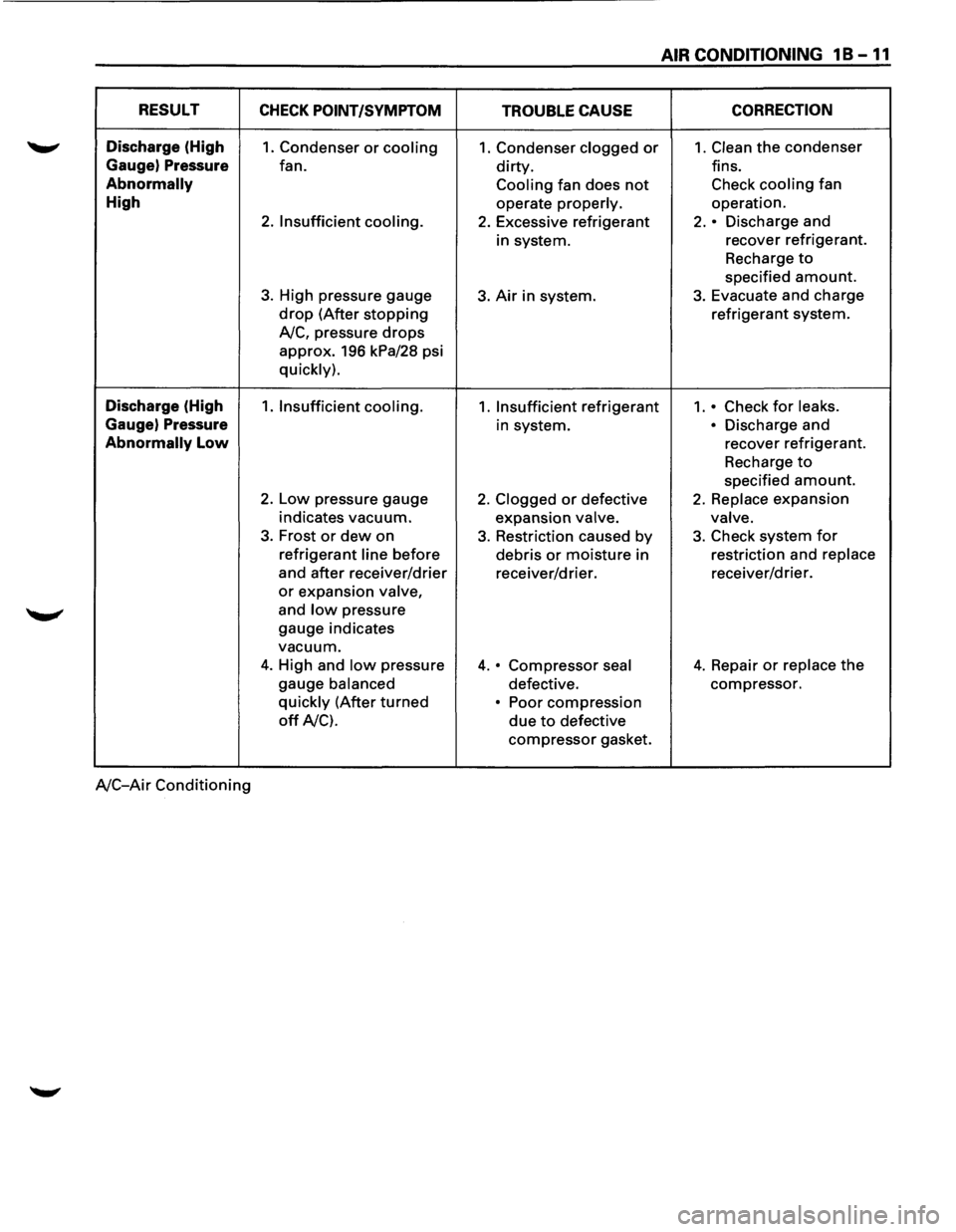
RESULT CHECK POINT/SYMPTOM TROUBLE CAUSE CORRECTION
Discharge
(High 1. Condenser or cooling 1. Condenser clogged or 1. Clean the condenser
Gauge) Pressure fan. dirty. fins.
Abnormally Cooling fan does not Check cooling fan
High operate properly. operation.
2. Insufficient cooling. 2. Excessive refrigerant 2. • Discharge and
in system. recover
refrigerant.
Recharge
to
specified amount.
3. High pressure gauge 3. Air in system. 3. Evacuate and charge
drop (After stopping refrigerant system.
A/C, pressure
drops
approx. 196 kPa/28 psi
quickly).
Discharge (High 1. Insufficient cooling. 1. Insufficient refrigerant 1 .• Check for leaks.
Gauge)
Pressure in system. • Discharge and
Abnormally Low recover refrigerant.
Recharge
to
specified amount.
2. Low pressure gauge 2. Clogged or defective 2. Replace expansion
indicates vacuum.
expansion
valve. valve.
3. Frost or dew on 3. Restriction caused by 3. Check system for
refrigerant line before
debris or moisture in restriction
and replace
and after receiver/drier
receiver/drier. receiver/drier.
or expansion valve,
and low pressure
gauge indicates
vacuum.
4. High and low pressure 4. • Compressor seal 4. Repair or replace the
gauge balanced defective. compressor.
quickly (After turned • Poor
compression
off A/C). due to defective
compressor gasket.
A/C-Air Conditioning
Page 89 of 1928
COMPRESSOR OVERHAUL 1 D - 1
SECTION 10
COMPRESSOR OVERHAUL
CONTENTS
General Description . . . . . . . . . . . . . . . . . . . . . 1 D-1
Diagnosis . . . . . . . . . . . . . . . . . . . . . . . . . . . . . 1
D-2
General Information . . . . . . . . . . . . . . . . . . . . 1 D-3
Compressor Oil . . . . . . . . . . . . . . . . . . . . . . 1 D-3
Service Procedures . . . . . . . . . . . . . . . . . . . . . 1D-5
Magnetic Clutch Assembly . . . . . . . . . . . . . 1 D-5
Main Data and Specifications . . . . . . . . . . . . . 1 D-8
General Specifications . . . . . . . . . . . . . . . . . 1 D-8
Torque Specifications . . . . . . . . . . . . . . . . . 1 D-8
Special Tools . . . . . . . . . . . . . . . . . . . . . . . . . . 1D-9
GENERAL DESCRIPTION
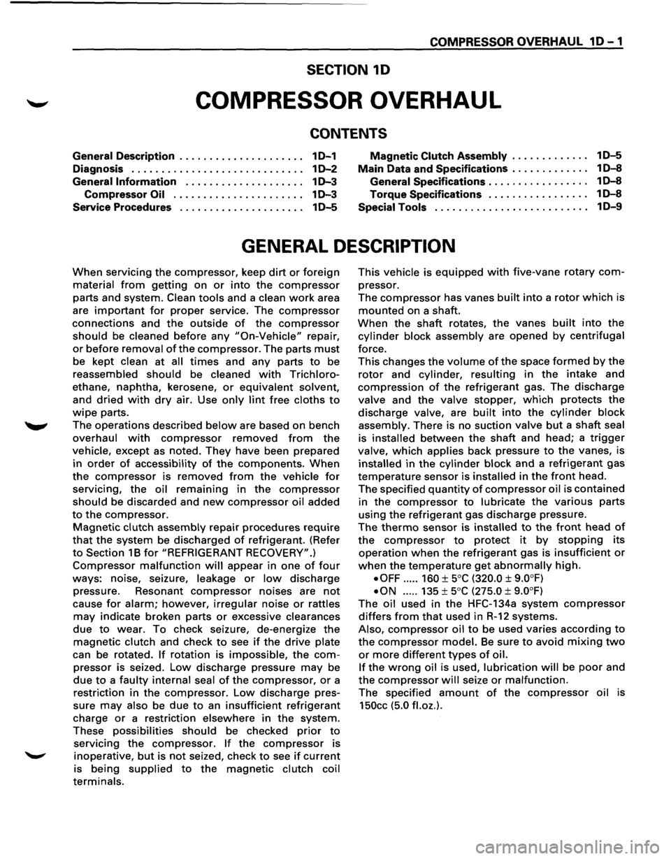
When servicing the compressor, keep dirt or foreign
material from getting on or into the compressor
parts and system. Clean tools and a clean work area
are
important for proper service. The compressor
connections and the outside of the compressor
should be cleaned before any "On-Vehicle" repair,
or before removal of the compressor. The parts must
be kept clean at all times and any parts to be
reassembled
should be cleaned with Trichloro
ethane, naphtha, kerosene, or equivalent solvent,
and
dried with dry air. Use only lint free cloths to
wipe parts.
The
operations described below are based on bench
overhaul
with compressor removed from the
vehicle, except as noted. They have been prepared
in
order of accessibility of the components. When
the compressor is removed from the vehicle for
servicing, the oil remaining in the compressor
should be discarded and new compressor oil added
to the compressor.
Magnetic clutch assembly repair procedures require
that the system be discharged of refrigerant. (Refer
to Section 1 B for "REFRIGERANT RECOVERY".)
Compressor malfunction will appear in one of four
ways: noise, seizure, leakage or low discharge
pressure. Resonant
compressor noises are not
cause for alarm; however, irregular noise or rattles
may indicate broken parts or excessive clearances
due to wear. To check seizure, de-energize the
magnetic clutch and check to see if the drive plate
can be rotated.
If rotation is impossible, the com
pressor is seized. Low discharge pressure may be
due to a faulty internal seal of the compressor, or a
restriction in the compressor.
Low discharge pres
sure
may also be due to an insufficient refrigerant
charge
or a restriction elsewhere in the system.
These possibilities
should be checked prior to
servicing the compressor. If the compressor is
inoperative,
but is not seized, check to see if current
is being supplied to the magnetic clutch coil
terminals.
This vehicle is equipped with five-vane rotary com
pressor.
The
compressor has vanes built into a rotor which is
mounted on a shaft.
When the shaft rotates, the vanes built into the
cylinder block assembly are opened by centrifugal
force.
This changes the volume of the space formed by the
rotor and cylinder, resulting in the intake and
compression of the refrigerant gas. The discharge
valve and the
valve stopper, which protects the
discharge valve, are
built into the cylinder block
assembly. There is no suction valve but a shaft seal
is
installed between the shaft and head; a trigger
valve, which applies back pressure to the vanes, is
installed in the cylinder block and a refrigerant gas
temperature sensor is installed in the front head.
The specified
quantity of compressor oil is contained
in
the compressor to lubricate the various parts
using
the refrigerant gas discharge pressure.
The thermo sensor is installed to the front head of
the compressor to protect it by stopping its
operation when the refrigerant gas is insufficient or
when the temperature get abnormally high.
•OFF ..... 160 ±soc (320.0 ± 9.0°F)
•ON ..... 135 ±soc (275.0 ± 9.0°F)
The oil used in the HFC-134a system compressor
differs from that used in R-12 systems.
Also, compressor
oil to be used varies according to
the compressor model. Be sure to avoid mixing two
or more different types of oil.
If the wrong oil is used, lubrication will be poor and
the compressor will seize or malfunction.
The specified
amount of the compressor oil is
150cc (5.0 fl.oz.).
Page 500 of 1928
6-2 ENGINE DIAGNOSIS
SECTION 6E-DRIVEABILITY
AND EMISSIONS
This section covers emission control systems general
information, and diagnostic procedures which will lead
to repairing performance and driveability related
problems.
Emission components are covered, as well
as removal and replacement procedures.
Instructions on use
of special tools are also given.
SECTION 6F-ENGINE EXHAUST
This section has information on all exhaust system
parts, such
as tailpipes, mufflers, and the catalytic
converter.
GENERAL DESCRIPTION
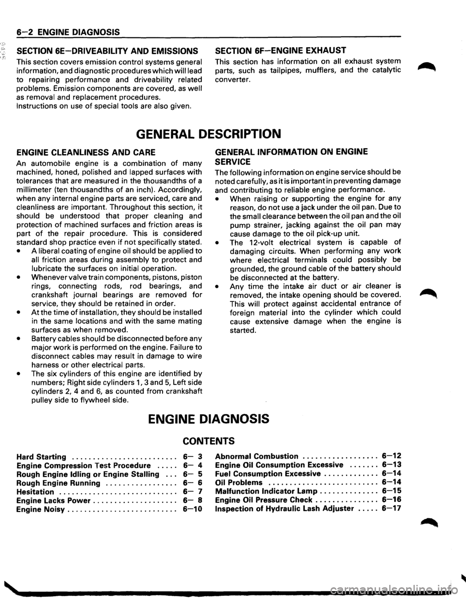
ENGINE CLEANLINESS AND CARE
An automobile engine is a combination of many
machined, honed,
polished and lapped surfaces with
tolerances that are measured in the thousandths of a
millimeter (ten thousandths of an inch). Accordingly,
when any
internal engine parts are serviced, care and
cleanliness are important. Throughout this section, it
should be understood that proper cleaning and
protection
of machined surfaces and friction areas is
part
of the repair procedure. This is considered
standard shop practice even
if not specifically stated.
• A liberal coating of engine oil should be applied to
all friction areas during assembly to protect and
lubricate the surfaces on initial operation.
• Whenever valve train components, pistons, piston
rings, connecting rods, rod bearings, and
crankshaft
journal bearings are removed for
service, they should be retained in order.
• At the time of installation, they should be installed
in the same locations and with the same mating
surfaces
as when removed.
• Battery cables should be disconnected before any
major
work is performed on the engine. Failure to
disconnect
cables may result in damage to wire
harness
or other electrical parts.
• The six cylinders of this engine are identified by
numbers; Right side
cylinders 1, 3 and 5, Left side
cylinders 2, 4 and 6, as counted from crankshaft
pulley side to flywheel side.
GENERAL INFORMATION ON ENGINE
SERVICE
The following information on engine service should be
noted
carefully, as it is important in preventing damage
and contributing
to reliable engine performance.
• When raising or supporting the engine for any
reason,
do not use a jack under the oil pan. Due to
the
small clearance between the oil pan and the oil
pump strainer, jacking against the oil pan may
cause damage to the
oil pick-up unit.
• The 12-volt electrical system is capable of
damaging circuits. When performing any work
where electrical terminals could possibly be
grounded, the ground cable of the battery should
be disconnected at the battery.
• Any time the intake air duct or air cleaner is
removed, the intake opening
should be covered.
This
will protect against accidental entrance of
foreign material into the cylinder which could
cause extensive damage when the engine is
started.
ENGINE DIAGNOSIS
CONTENTS
Hard Starting . . . . . . . . . . . . . . . . . . . . . . . . . 6-3
Engine Compression
Test Procedure ..... 6-4
Rough Engine
Idling or Engine Stalling . . . 6-5
Rough Engine Running . . . . . . . . . . . . . . . . .
6-6
Hesitation . . . . . . . . . . . . . . . . . . . . . . . . . . . . 6-7
Engine Lacks
Power . . . . . . . . . . . . . . . . . . . . 6-8
Engine
Noisy .......................... 6-10
Abnormal Combustion . . . . . . . . . . . . . . . . . . 6-12
Engine Oil Consumption Excessive . . . . . . . 6-13
Fuel Consumption Excessive ............. 6-14
Oil Problems . . . . . . . . . . . . . . . . . . . . . . . . . . 6-14
Malfunction Indicator Lamp . . . . . . . . . . . . . . 6-15
Engine Oil Pressure Check ............... 6-16
Inspection of Hydraulic Lash Adjuster . . . . . 6-17
Page 556 of 1928
6A-40 GENERAL ENGINE MECHANICAL
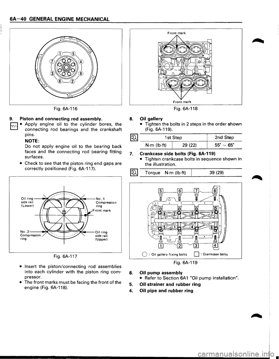
Fig. 6A-116
9. Piston and connecting rod assembly.
Cl • Apply engine oil to the cylinder bores, the
L:J connecting rod bearings and the crankshaft
pins.
NOTE:
Do not apply engine oil to the bearing back
faces and the connecting rod bearing fitting
surfaces.
• Check to see that the piston ring end gaps are
correctly positioned (Fig. 6A-117).
Oil ring--~~~=!==:::;:,.::~~--No.1 side rail Compression (Lower) ring
Front mark
No. 2--~~~~i::::::=~~;(.,.--Oil ring Compression side rail ring (Upper)
Fig. 6A-117
• Insert the piston/connecting rod assemblies
into each cylinder with the piston ring com
pressor.
• The front marks must be facing the front of the
engine (Fig. 6A-118).
8.
Front mark
Front mark
Fig. 6A-118
Oil gallery
• Tighten the bolts in 2 steps in the order shown
(Fig. 6A-119).
1~1 _________ 1s_t,s_te~p ________ +-_2_n_d_S_t_e_p ___
7.
N·m (lb·ftl 29 (22) ss· -ss·
Crankcase side bolts (Fig. &A-119)
• Tighten crankcase bolts in sequence shown in
the
illustration.
I~I __ T_o_r~qu_e __ N_·_m __ (lb_·ft_)~ ______ 3_9_(2_9_l ____ _
Q : Oil gallery fixing bolts 0 : Crankcase bolts
Fig. 6A-119
6. Oil pump assembly
• Refer to Section 6A 1 "Oil pump installation".
5. Oil strainer and rubber ring
4.
Oil pipe and rubber ring
•
Page 561 of 1928
CYLINDER BLOCK
The cylinder block is made of aluminum die-cast
casting
for 75° V-type six cylinders. It has a rear plate
integrated structure and employs a deep skirt. The
cylinder liner is cast and the liner inner diameter and
crankshaft
journal diameter are classified into grades.
The crankshaft is supported by four bearings
of which
width is different between No.2, No.3 and No.1, No.4;
the
width of No.3 bearing on the body side is different
in order
to support the thrust bearing. The bearing cap
is made
of nodular cast iron and each bearing cap uses
four bolts and two side bolts.
CYLINDER HEAD
The cylinder head, made of aluminum alloy casting
employs a pent-roof type combustion chamber with a
spark
plug in the center.
The intake and exhaust
valves are placed in V-type
design. The ports are cross-flow type.
VALVE TRAIN
SOHC: The camshafts on both banks are driven by a
timing
belt to operate the valves via rocker arm.
No
further valve clearance adjustment is
required, due
to the Hydraulic lash adjuster
attachedtotherockerarm.
DOHC: Intake camshaft on the both sides of banks are
driven through a
timing belt, while exhaust
camshaft are driven by the both sides
of intake
camshaft through chains.
The driven camshafts open and
close valves
through swing arms.
Valve clearance is automatically adjusted by
means
of HLA built in the cylinder head.
INTAKE MANIFOLD
SOHC: The intake manifold system is composed ofthe
aluminum cast common chamber and intake
manifold attached with six fuel injectors.
DOHC: The intake manifold system is composed of the
aluminum cast common chamber duct having
the induction
control valve, common chamber
and intake
manifold attached with six fuel
injectors.
EXHAUST MANIFOLD
The exhaust manifold is made of nodular cast iron.
PISTONS AND CONNECTING RODS
Aluminum pistons are used after selecting the grade
that meets the cylinder bore diameter. Each piston has
two compression rings and one oil ring. The piston pin
made
of chromium steel is offset 1 mm toward the
thrust side, and the thrust pressure
of piston to the
cylinder wall varies gradually as the piston travels. The
connecting rods are made
of forged steel. The
connecting rod bearings are graded
for correct size
selection.
ENGINE (V6 3.2L DOHC AND SOHC) 6A1-3
CRANKSHAFT AND BEARINGS
The crankshaft is made of Ductile cast-iron.Pins and
journals are graded for correct size selection for their
bearing.
OIL PUMP
The trochoid-type oil pump is driven by crankshaft.
Operation and service procedures are described in this
section.
ENGINE LUBRICATION
The oil discharged by a trochoid-type oil pump driven
by the crankshaft is fed through full-flow oil filter and
engine
coolant cooled oil cooler up to the oil gallery
provided under the crankshaft bearing cap. The oil is
then
led to the crankshaft journals and cylinder head.
The crank pins are
lubricated with oil from crankshaft
journals through oil holes. Also, an oil jet is fed to each
cylinder from crankshaft journals on the connecting
rod
for piston cleaning. The oil pan flange is sealed with
liquid packing only; do not deform or damage the
flange surface during removal or installation.
Page 621 of 1928
·-------------------------------------
ENGINE (V6 3.2L DOHC AND SOHC) 6A1-63
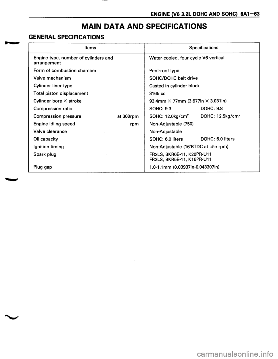
MAIN DATA AND SPECIFICATIONS
GENERAL SPECIFICATIONS
Items S pacifications
Engine type,
number of cylinders and Water-cooled, four cycle V6 vertical
arrangement
Form
of combustion chamber
Pent-roof type
Valve mechanism SOHC/DOHC belt drive
Cylinder liner type
Casted in cylinder block
Total
piston displacement
3165 cc
Cylinder bore X stroke 93.4mm X 77mm (3.677in X 3.031 in)
Compression ratio
SOHC: 9.3 DOHC: 9.8
Compression pressure
at
300rpm SOHC: 12.0kg/cm2 DOHC: 12.5kg/cm2
Engine idling speed rpm Non-Adjustable (750)
Valve clearance Non-Adjustable
Oil capacity SOHC: 6.0 liters DOHC:
6.0 liters
Ignition
timing Non-Adjustable (16.BTDC at Idle rpm)
Spark
plug FR2LS, BKR6E-11, K20PR-U11
FR3LS, BKR5E-11 I K16PR-U11
Plug gap 1.0-1.1 mm (0.03937in-0.043307in)
Page 788 of 1928
6E2-92 DRIVEABILITY AND EMISSIONS
LACK OF POWER, SLUGGISH OR SPONGY
Definition: Engine delivers less than expected power.
Little or no increase in speed when
accelerator
pedal is pushed down part
way.
PRELIMINARY CHECKS
• Perform the careful visual/physical checks as
described at start of "Symptoms," Section "6E2-
B."
•
Compare customer's car to similar unit. Make sure
the
vehicle has an actual problem.
• Remove air filter and check air filter for dirt, or for
being plugged. Replace as necessary.
FUEL SYSTEM
• CHECK: Rescricted fuel filter.
• CHECK: Fuel pressure, use CHART A-7.
• CHECK: Contaminated fuel.
• CHECK: Fuel injectors are correct for the vehicle.
IGNITION SYSTEM
• CHECK: Ignition timing, using "Scan tool".
• CHECK: Knock sensor system for excessive spark
retard activity. Refer to CHART
C-5. Use
"Scan tool".
• CHECK: Secondary voltage using an oscilloscope
or a spark tester J 26792 (ST-125), or
equivalent, to check for a weak coil.
ADDITIONAL CHECKS
• CHECK: Engine control module grounds for being
clean,
tight and in their proper locations.
See engine control module wiring
diagrams.
• CHECK: Exhaust gas recirculation operation for
being open or partly open all the time.
- Refer to CHART
C-7.
• CHECK: Generator output voltage. Repair if less
than 9
or more than 16 volts.
• CHECK: Exhaust system for possible restriction.
Refer
to CHART B-1.
-Inspect exhaust system for damaged
or collapsed pipes.
-
Inspect muffler for heat damage or
possible internal failure.
• CHECK: Torque converter clutch for proper
operation. Refer
to AUTOMATIC
TRANSMISSION
(SECTION 7A).
ENGINE MECHANICAL
• CHECK: Engine valve timing and compression.
• CHECK: Engine for correct or worn camshaft.
Refer
to ENGINE MECHANICAL
DIAGNOSIS
(SECTION 6A).
DETONATION/SPARK KNOCK
Definition: A mild to severe ping, usually worse under
acceleration. The engine makes sharp
metallic knocks that change with throttle
opening.
Sounds like popcorn popping.
PRELIMINARY CHECKS
• Perform the careful visual/physical checks as
Low engine coolant.
Restricted air
flow to radiator, or restricted
water flow through radiator.
Correct engine
coolant solution should be a 50/
50 mix of anti-freeze engine coolant (or
equivalent) and water.
described at start
of "Symptoms," Section "6E2-FUEL SYSTEM
B."
•
Park/Neutral position switch. Be sure "Scan tool"
indicates drive with gear selector in drive or
overdrive. Use
CHART C-1A.
• If "Scan tool" readings are normal (see facing page
of on-board diagnostic system check) and there
are no engine mechanical faults,
fill fuel tank with a
gasoline
that has a minimum octane reading of 87
and revaluate vehicle performance.
• CHECK: Exhaust gas recirculation system for not
opening. Use CHART C-7.
COOLING SYSTEM
• Check for obvious overheating problems:
• NOTICE: To determine if the condition is caused by
a rich
or lean system, the car should be
driven at the speed
of the complaint.
Monitoring
LT. Fuel Trim will help
identify problem.
Lean-
LT. Fuel Trim above 142. Refer to
"Diagnostic Aids" on facing page of
diagnostic trouble code 44.
Rich-LT. Fuel Trim below 118. Refer to
"Diagnostic Aids" on facing page of
diagnostic trouble code 45.
• CHECK: Fuel pressure, use CHART A-7.
..
Page 789 of 1928
IGNITION SYSTEM
• CHECK: Spark plugs for proper heat cause. Refer
to Owner's Manual.
• CHECK: Ignition timing, using a "Scan tool".
ENGINE MECHANICAL
• CHECK: For excessive oil in the combustion
chamber. -
Valve oil seals for leaking.
• CHECK: Combustion chambers for excessive
carbon
build up. Remove carbon with top
engine cleaner and follow instructions on
can.
DRIVEABILITY AND EMISSIONS 6E2-93
• CHECK: Combustion chamber pressure by
performing a compression test.
See
ENGINE MECHANICAL DIAGNOSIS
(SECTION 6A).
• CHECK: For incorrect basic engine parts such as
cam, heads, pistons, etc.
HESITATION, SAG, STUMBLE
Definition: Momentary lack of response as the
accelerator is pushed down. Can occur at
all car speeds. Usually most severe when
first trying
to make the car move, as from a
stop sign. May cause engine to
stall if
severe enough.
PRELIMINARY CHECKS
• Perform the careful visual/physical checks as
described at start of "Symptoms," Section "6E2-
B."
SENSORS
• CHECK: Throttle position sensor for binding or
sticking. Voltage should increase at a
steady
rate as throttle is moved toward
Wide Open Throttle.
• CHECK: Manifold absolute pressure sensor-use
CHART C-10.
FUEL SYSTEM
• CHECK: Fuel pressure, use CHART A-7.
• CHECK: Fuel injectors are correct for vehicle.
• CHECK: Contaminated fuel.
• CHECK: Evaporative emission canister purge
system
for proper operation. Refer to
"Evaporative Emission Control System,"
Section "6E2-C3."
IGNITION SYSTEM
• CHECK: Spark plugs for being fouled, or for faulty
secondary wiring.
• CHECK: Ignition timing, using a "Scan tool".
• CHECK: Ignition system ground.
ADDITIONAL CHECKS
• CHECK: Exhaust gas recirculation operation, use
CHART
C-7.
• CHECK: Engine thermostat functioning correctly
and proper heat range.
• CHECK: Generator output voltage. Repair if less
than 9 or more than 16 volts.
CUTS OUT, MISSES
Definition: Steady pulsation or jerking that follows
engine speed, usually more pronounced
as engine load increases, not normally felt
above 1500 revolution per minute or 48
kph
(30 mile per hour). The exhaust has a
steady spitting sound at
idle or low speed.
PRELIMINARY CHECKS
• Perform the careful visual/physical checks as
described at start of "Symptoms," Section "6E2-
B."
IGNITION SYSTEM
• Check for cylinder miss by:
1. Start engine, allow engine to stabilize then
disconnect
idle air control motor. Remove
one spark
plug wire at a time, using insulated
pliers.
CAUTION: Do not perform this test for
more than 2 minutes,
as this test may
cause damage to the three
way
catalytic converter.
2. If there is a revolution per minute drop on all
cylinders (equal
to within 50 revolution per
minute), go
to "Rough, Unstable, or Incorrect
Idle, Stalling"
symptom. Reconnect idle air
control valve.
Page 790 of 1928
6E2-94 DRIVEABILITY AND EMISSIONS
3. If there is no revolution per minute (rpm) drop
on one or more cylinders, or excessive
variation is drop, check
for spark on the
suspected
cylinder(s) using a shop
oscilloscope or with J 26792 (ST-125) spark
tester
or equivalent. If no spark, refer to
ENGINE ELECTRICAL (SECTION 6D) for
intermittent operation of miss. If there is a
spark, remove spark
plug(s) in these cylinders
and check for:
-
Insulator Cracks.
- Wear.
-
Improper Gap.
- Burned
Electrodes.
-Heavy Deposits.
• CHECK: Spark plug wires by connecting
ohmmeter to ends of each wire in
question.
If meter reads over 30,000
ohms, replace wire(s).
FUEL SYSTEM
• CHECK: Fuel system -Plugged fuel filter, low
pressure. Use CHART A-7.
• CHECK: Contaminated fuel.
• CHECK: Injector drivers. Disconnect all injector
harness connectors. Connect
J 34730-2
Injector Test Light or equivalent 6 volts
test light between the harness terminal,
of each injector connector and note light
while
cranking. If test light fails to blink at
any connector, it is a faulty injector drive
circuit harness, connector
or terminal.
ENGINE MECHANICAL
• CHECK: Compression. Perform compression
check on
questionable cylinder(s) found
above.
If compression is low, repair as
necessary. Refer to ENGINE
MECHANICAL DIAGNOSIS (SECTION
6A).
• CHECK: Engine parts. Remove cam covers.
Check
for broken valve springs, worn
camshaft lobes and valve timing. Repair
as necessary. See ENGINE MECHANICAL
DIAGNOSIS (SECTION
6A).
ADDITIONAL CHECKS
• CHECK: For electromagnetic interference (EMI).
A missing condition can be caused by EMI
on the reference circuit. EMI can usually
be detected by monitoring engine speed
with a "Scan tool". A sudden increase in
rpm
with little change in actual engine
speed change, indicates
EMI is present. If
the problem exists, check routing of
secondary wires, check distributor
ground circuit.
• CHECK: Intake and exhaust manifold passage for
casting
flash.
ROUGH, UNSTABLE, OR INCORRECT IDLE, STALLING
Definition: Engine runs unevenly at idle. If severe, the
engine
or car may shake. Engine idle
speed may vary in rpm. Either condition
may be severe enough to stall engine.
PRELIMINARY CHECKS
• Perform the careful visual/physical checks as
described at start
of "Symptoms," Section "6E3-
B."
• CHECK:
• CHECK:
For vacuum leaks
Engine control module (ECM) grounds for
being clean, tight and proper routing.
See ECM wiring diagrams.
FUEL SYSTEM
• NOTICE: Monitoring L.T. Fuel Trim will help
identify the cause of the problem. If the
system is running
lean (LT. Fuel Trim
greater than 142), refer
to "Diagnostic
Aids"
on facing page of diagnostic trouble
code 44.
If the system is running rich (L.T. Fuel
Trim less than 118), refer to "Diagnostic
Aids" on facing page of diagnostic trouble
code 45.
• CHECK:
• CHECK:
• CHECK:
• CHECK:
• CHECK:
Incorrect minimum idle speed may be
caused
by foreign material accumulation
in the throttle bore coking, on the throttle
body or on the throttle shaft.
Clean injectors.
For
fuel in fuel pressure control valve
hose. If fuel is present, replace regulator
assembly.
Evaporative Emission Control System,
refer to "Evaporative Emission Control
System," Section "6E2-C3".
The Heated oxygen sensor should
respond quickly to different throttle
position, if it does not, check the heated
oxygen sensor
for silicon contaminations
from fuel, or use of improper RTV sealant.
The sensor will have a white, powdery
coating and will result in a high but false
signal voltage
(rich heated oxygen sensor
signal indication). The ECM will then
reduce the
amount of fuel delivered to the
engine, causing a severe
driveability
problem.
II