brake ISUZU TROOPER 1995 Owner's Guide
[x] Cancel search | Manufacturer: ISUZU, Model Year: 1995, Model line: TROOPER, Model: ISUZU TROOPER 1995Pages: 1928
Page 248 of 1928
48-6 REAR AXLE
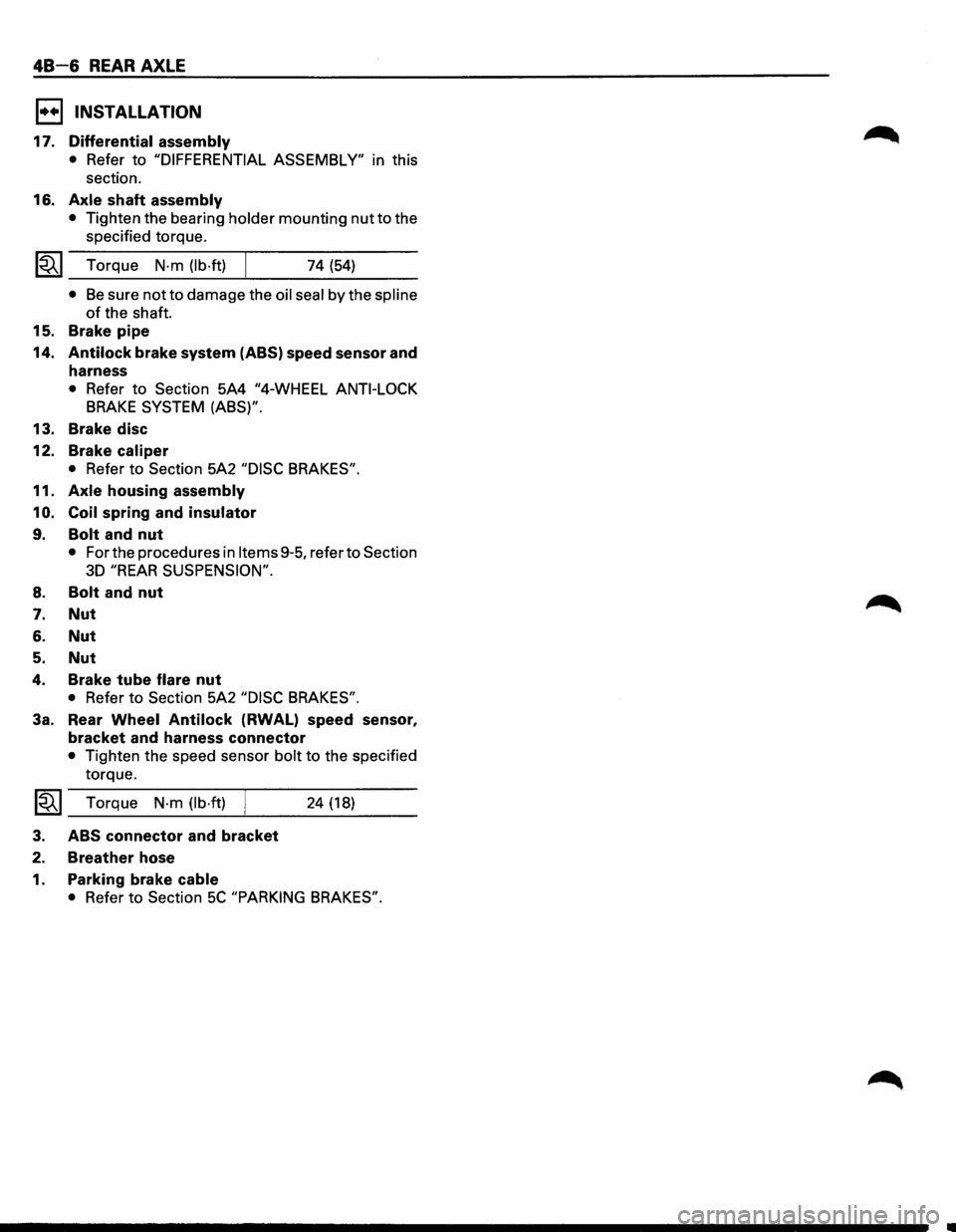
1••1 INSTALLATION
17. Differential assembly
• Refer to "DIFFERENTIAL ASSEMBLY" in this
section.
16.
Axle shaft assembly
• Tighten the bearing holder mounting nut to the
specified torque.
~~~ Torque N·m (lb·ft) 74 (54)
• Be sure not to damage the oil seal by the spline
of the shaft.
15. Brake
pipe
14. Antilock brake system (ABS) speed sensor and
harness
• Refer to Section 5A4 "4-WHEEL ANTI-LOCK
BRAKE SYSTEM (ABS)".
13. Brake disc
12. Brake
caliper
• Refer to Section 5A2 "DISC BRAKES".
11.
Axle housing assembly
10. Coil spring and insulator
9. Bolt and nut
• For the procedures in Items 9-5, refer to Section
3D "REAR SUSPENSION".
8. Bolt and nut
7. Nut
6. Nut
5. Nut
4. Brake tube flare nut
• Refer to Section 5A2 "DISC BRAKES".
3a. Rear Wheel Antilock (RWAL) speed sensor,
bracket and harness connector
• Tighten the speed sensor bolt to the specified
torque.
1~1 Torque N-m (lb·ft) j 24 (18)
3. ABS connector and bracket
2. Breather hose
1. Parking brake cable
• Refer to Section 5C "PARKING BRAKES".
Page 249 of 1928
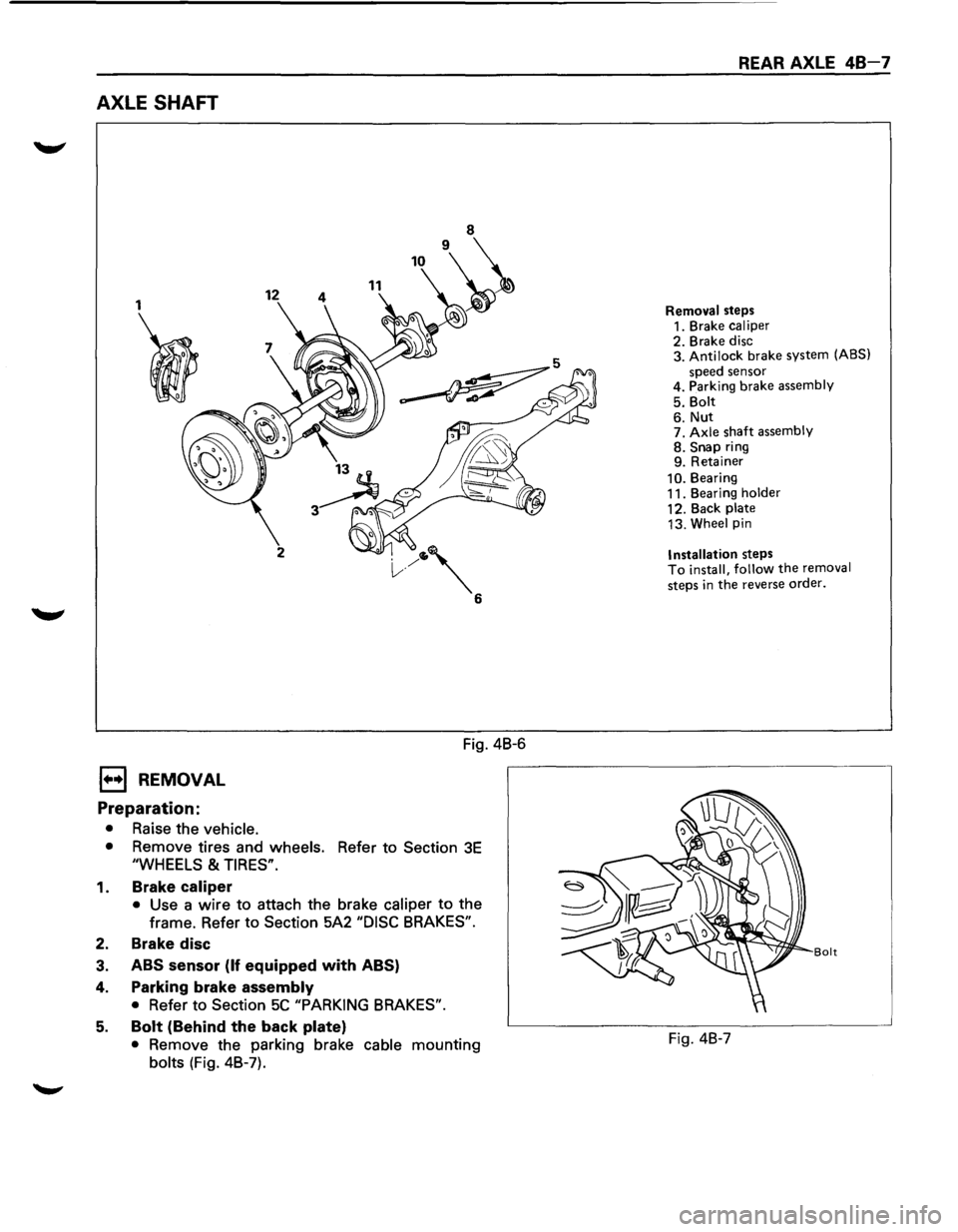
AXLE SHAFT
1
I
1••1 REMOVAL
Preparation:
• Raise the vehicle.
12 11
2
Fig. 4B-6
• Remove tires and wheels. Refer to Section 3E
"WHEELS & TIRES".
1. Brake caliper
• Use a wire to attach the brake caliper to the
frame. Refer to
Section 5A2 "DISC BRAKES".
2. Brake disc
3. ABS sensor (If equipped with ABS)
4. Parking brake assembly
• Refer to Section 5C "PARKING BRAKES".
5. Bolt (Behind the back plate)
• Remove the parking brake cable mounting
bolts (Fig. 4B-7).
REAR AXLE 48-7
Removal steps
1. Brake caliper
2. Brake disc
3. Antilock brake system (ABS)
speed sensor
4. Parking brake assembly
5. Bolt
6. Nut 7. Axle shaft assembly 8. Snap ring
9. Retainer
10. Bearing
11. Bearing holder
12. Back plate
13. Wheel pin
Installation steps To install, follow the removal
steps
in the reverse order.
Bolt
Fig. 4B-7
Page 251 of 1928
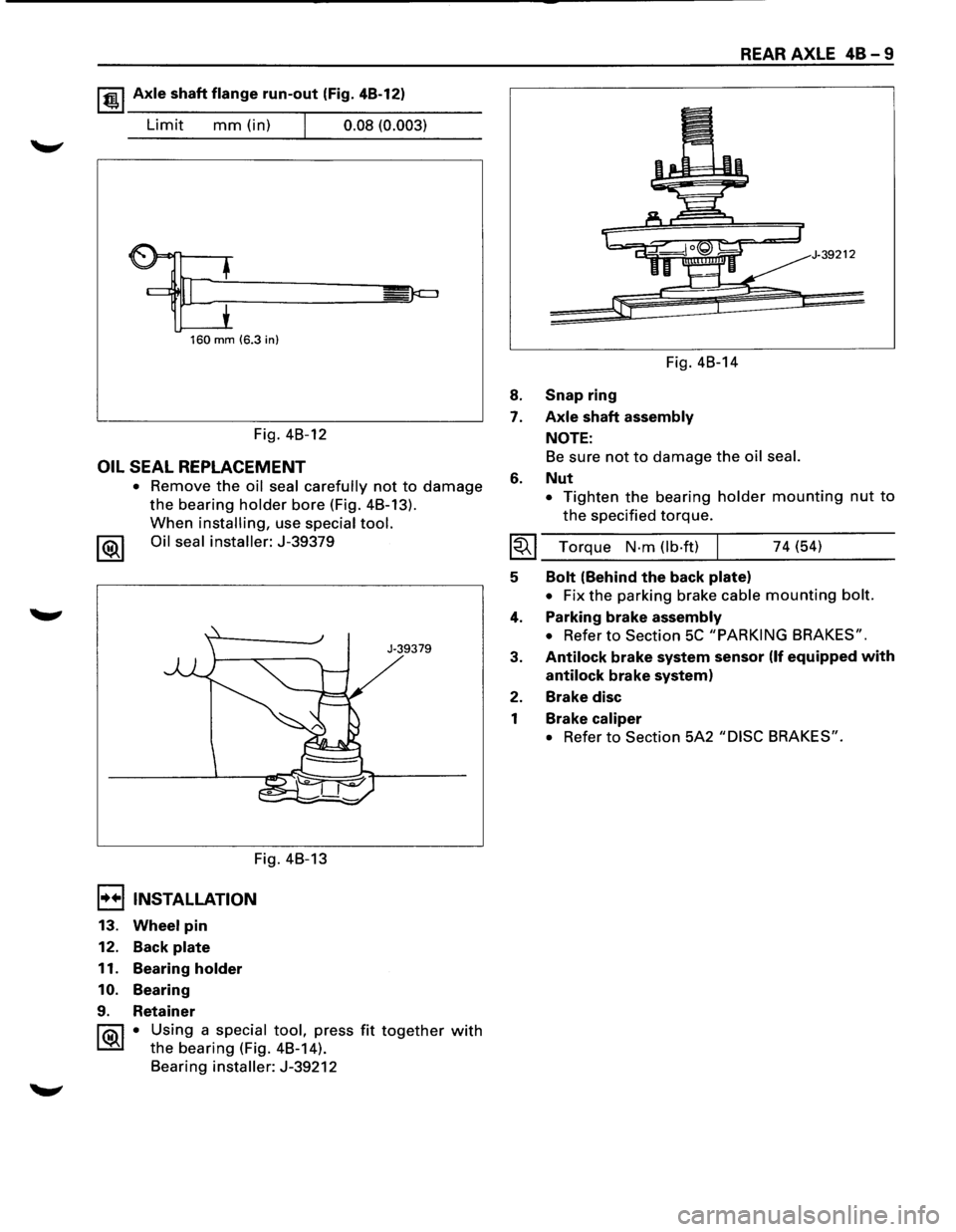
1 t!!.l Axle shaft flange run-out (Fig. 4B-12)
Limit mm (in) I 0.08 (0.003)
160 mm (6.3 in)
Fig. 4B-12
OIL SEAL REPLACEMENT
• Remove the oil seal carefully not to damage
the bearing holder bore (Fig. 4B-13).
When installing, use special tool.
1®1 Oil seal installer: J-39379
Fig. 4B-13
I••IINSTALLATION
13. Wheel pin
12. Back plate
11. Bearing holder
10. Bearing
9. Retainer
J-39379
1 ®I • Using a special tool, press fit together with
the bearing (Fig. 4B-14).
Bearing
installer: J-39212
8.
7.
6.
Fig. 4B-14
Snap ring
Axle shaft assembly
NOTE:
REAR AXLE 48-9
39212
Be sure not to damage the oil seal.
Nut
• Tighten the bearing holder mounting nut to
the specified torque.
I~I ___ T_o_rq_u_e __ N_·_m_(_lb_·f_t)~l _____ 7_4_(~5~4) ____ ___
5
4.
3.
2.
1
Bolt (Behind the back plate)
• Fix the parking brake cable mounting bolt.
Parking brake assembly
• Refer to Section 5C "PARKING BRAKES".
Antilock brake system sensor (If equipped with
antilock brake system)
Brake disc
Brake caliper
• Refer to Section 5A2 "DISC BRAKES".
Page 253 of 1928
E) INSTALLATION
5. Collapsible spacer
• Discard the used collapsible spacer and install
a new one.
4. Outer bearing
NOTE:
• Do not drive in, but just temporarily set in the
outer bearing
by hand, which should be
indirectly pressed in finally by tightening the
flange nut.
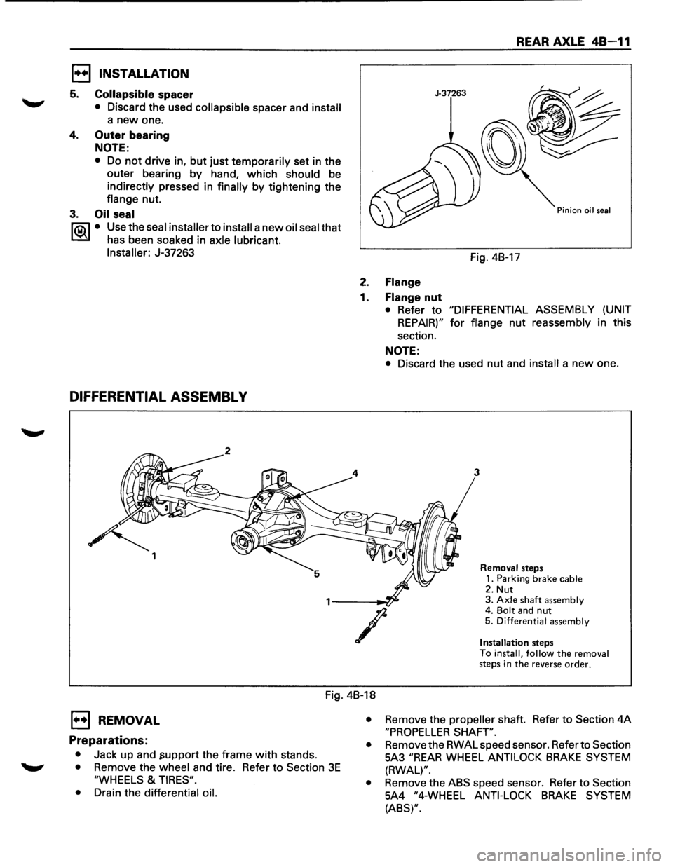
3. Oil seal
1"?.:\1 • Use the seal installer to install a new oil seal that
l.::::'i:il has been soaked in axle lubricant.
Installer:
J-37263
DIFFERENTIAL ASSEMBL V
~ 1
REAR AXLE 48-11
J-37263
Pinion oil seal
Fig. 4B-17
2. Flange
1. Flange nut
• Refer to "DIFFERENTIAL ASSEMBLY (UNIT
REPAIR)" for flange nut reassembly in this
section.
NOTE:
• Discard the used nut and install a new one.
3
/
Removal steps
1. Parking brake cable
2. Nut 3. Axle shaft assembly 4. Bolt and nut 5. Differential assembly
Installation
steps
To install, follow the removal steps in the reverse order.
Fig. 4B-18
E) REMOVAL
Preparations:
• Jack up and .support the frame with stands.
• Remove the wheel and tire. Refer to Section 3E
"WHEELS & TIRES".
•
Drain the differential oil. •
Remove
the propeller shaft. Refer to Section 4A
"PROPELLER SHAFT".
•
Remove the RWAL speed sensor. Refer to Section
5A3
"REAR WHEEL ANTILOCK BRAKE SYSTEM
(RWAL)".
•
Remove the ABS speed sensor. Refer to Section
5A4
"4-WHEEL ANTI-LOCK BRAKE SYSTEM
(ABS)".
Page 254 of 1928
48-12 REAR AXLE
1. Parking brake cable
• Remove the parking brake cable fastening clip
and disconnect the equalizer section. Refer
to
Section SC "PARKING BRAKES".
2. Nut
• Remove the bearing holder fixing nuts.
3. Axle shaft assembly
• Be sure notto damage the oil seal by axle shaft.
4.
Bolt and nut
• Remove differential carrier mounting bolts and
nuts.
5. Differential assembly
1••1 INSTALLATION
5. Differential assembly
• Clean the contact surfaces of the axle and
differential carrier.
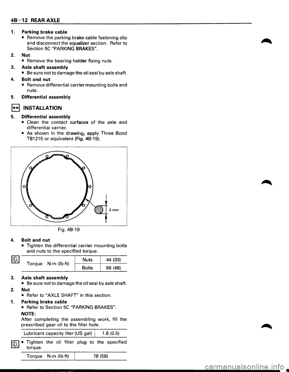
• As shown in the drawing, apply Three Bond
TB1215
or equivalent (Fig. 4B-19).
3mm
Fig. 4B-19
4. Bolt and nut
• Tighten the differential carrier mounting bolts
and nuts
to the specified torque.
Torque
N·m (lb·ft) Bolts Nuts
44
(33)
66 (48)
3. Axle shaft assembly
• Be sure notto damage
the oil seal by axle shaft.
2. Nut
• Refer to "AXLE SHAFT' in this section.
1. Parking brake cable
• Refer to Section 5C "PARKING BRAKES".
NOTE:
After completing the assembling work, fill the
prescribed gear
oil to the filler hole.
~·
Lubricant capacity liter (US gal) j 1.8 (0.5)
Tighten the oil filler plug to the specified
torque.
Torque
N·m (lb·ft) 78 (58)
Page 285 of 1928
l•!•l DISASSEMBLY
•
•
•
Jack up the vehicle and support it using jack
stands.
Remove the
tire and wheel.
Remove the drain bolt to drain differential oil.
NOTE:
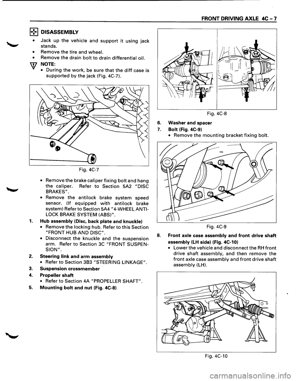
•
During the work, be sure that the diff case is
supported by the jack (Fig. 4C-7).
Fig.
4C-7
• Remov: the brake caliper fixing bolt and hang
the caliper. Refer to Section 5A2 "DISC
BRAKES".
•
Remove the antilock brake system speed
sensor.
(If equipped with antilock brake
system) Refer
to Section 5A4 "4-WHEEL ANTI
LOCK
BRAKE SYSTEM (ABS)".
1. Hub assembly (Disc, back plate and knuckle)
• Remove the locking hub. Refer to this Section
"FRONT HUB AND DISC".
•
Disconnect the knuckle and the suspension
arm. Refer
to Section 3C "FRONT SUSPEN
SION".
2. Steering link and arm assembly
• Refer to Section 3B3 "STEERING LINKAGE".
3. Suspension crossmember
4. Propeller shaft
• Refer to Section 4A "PROPELLER SHAFT".
5. Mounting bolt and nut (Fig. 4C-8)
FRONT DRIVING AXLE 4C-7
Fig. 4C-8
6. Washer and spacer
7. Bolt (Fig. 4C-9)
• Remove the mounting bracket fixing bolt.
Fig. 4C-9
8. Front axle case assembly and front drive shaft
assembly (LH side) (Fig. 4C-10)
• Lower the vehicle and disconnect the RH front
drive shaft assembly, and then remove the
front axle case assembly and front drive shaft
assembly (LH).
Fig. 4C-10
Page 286 of 1928
4C - 8 FRONT DRIVING AXLE
9. Front drive shaft assembly (RH)
l•!•l REASSEMBLY
9. Front drive shaft assembly (RH)
• Lay the assembly on the lower arm.
8. Front axle case assembly and front drive shaft
assembly (LH)
• Place the axle case on the jack, connect to the
front drive shaft assembly (RH) before
installing to the vehicle.
7. Bolt
• Tighten the mounting bracket fixing bolt to
the specified torque.
~~~ Torque N.m (lb.ft) I 116 (85)
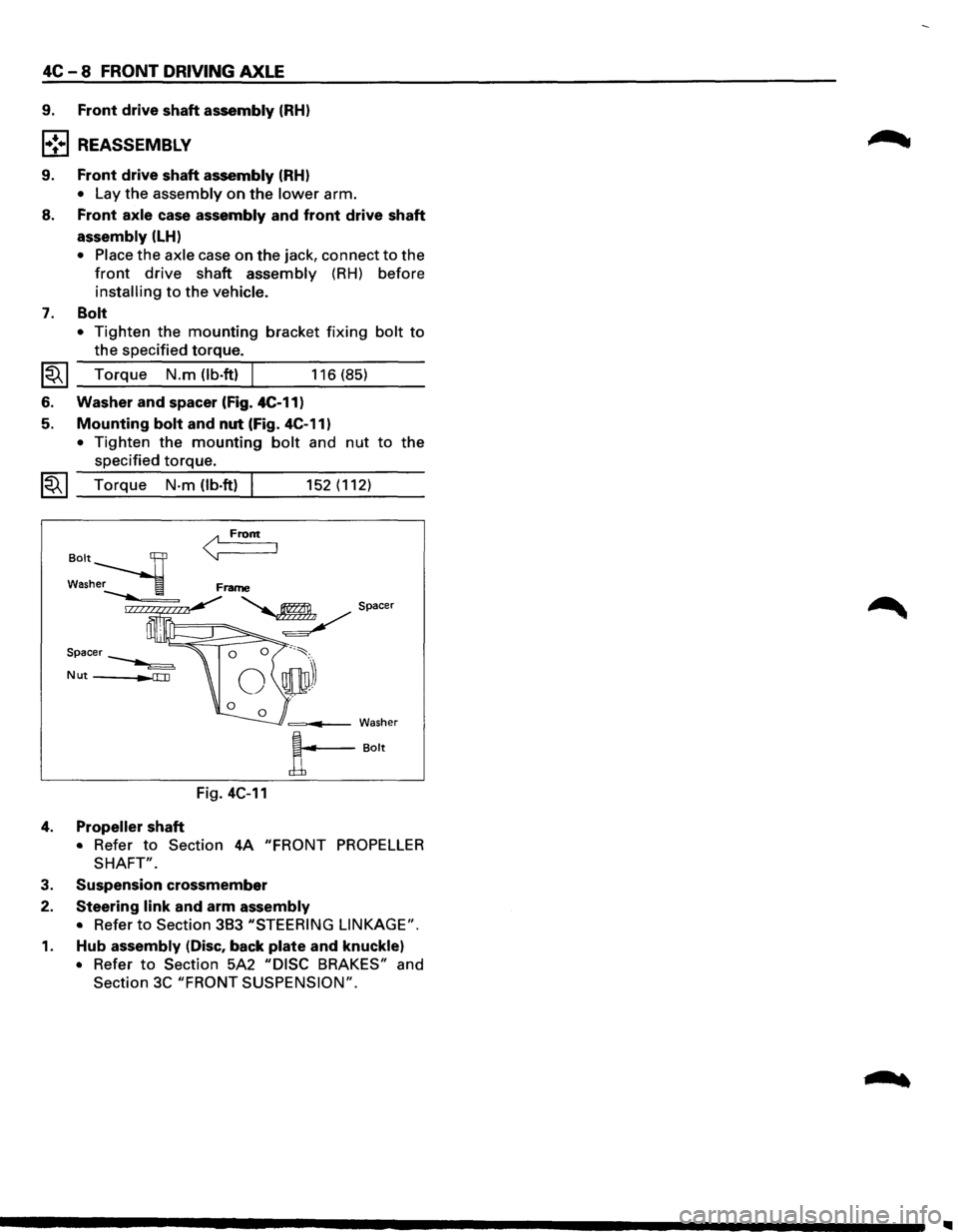
6. Washer and spacer (Fig. 4C-11)
5. Mounting bolt and nut (Fig. 4C-11)
• Tighten the mounting bolt and nut to the
specified torque.
~~~ Torque N·m (lb.ft) I 152 (112)
< From
=---Washer
A--Bolt
Fig. 4C-11
4. Propeller shaft
• Refer to Section 4A "FRONT PROPELLER
SHAFT".
3. Suspension crossmember
2. Steering link and arm assembly
• Refer to Section 383 "STEERING LINKAGE".
1. Hub assembly (Disc, back plate and knuckle)
• Refer to Section 5A2 "DISC BRAKES" and
Section
3C "FRONT SUSPENSION".
Page 307 of 1928
1•! .. 1 DISASSEMBLY
•
Shift the transfer lever to the "2H" position and
move the vehicle forward and rearward about
one meter.
• Remove the 14mm hex bolts.
• Before disassembly, jack up the front of vehicle
and
support frame with jack stands.
• Remove the disc brake caliper assembly and
hang
it on the frame with wires. Refer to Section
5A2
"DISC BRAKES".
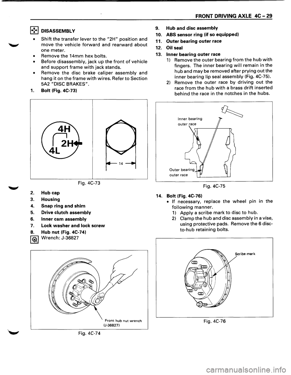
1. Bolt (Fig. 4C-73)
Fig. 4C-73
2. Hub cap
3. Housing
4. Snap ring and shim
5. Drive clutch assembly
6. Inner cam assembly
7. Lock washer and lock screw
8. Hub nut (Fig. 4C-74)
1®.1 Wrench: J-36827
Fig. 4C-74
Front hub nut wrench (J-36827)
FRONT DRIVING AXLE 4C-29
9. Hub and disc assembly
10. ABS
sensor ring (if so equipped)
11.
Outer bearing outer race
12.
Oil seal
13. Inner bearing outer race
1) Remove the outer bearing from the hub with
fingers. The inner bearing will remain in the
hub and may be removed after prying out the
inner bearing lip seal assembly (Fig. 4C-75).
2) Remove the outer race by driving out the
race from the hub with a brass drift inserted
behind
the race in the notches in the hubs.
Inner bearing
outer race
Fig. 4C-75
14.
Bolt (Fig. 4C-76)
• If necessary, replace the wheel pin in the
following manner.
1) Apply a scribe mark to disc to hub.
2) Clamp the hub and disc assembly in a vise,
using protective pads. Remove
the 6 disc
to-hub retaining bolts.
Scribe mark
Fig. 4C-76
Page 308 of 1928
4C -30 FRONT DRIVING AXLE
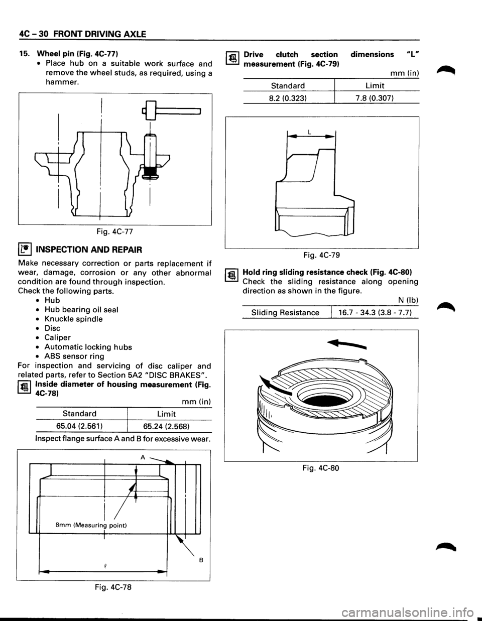
15. Wheel pin (Fig. 4C-77)
• Place
hub on a suitable work surface and
remove the
wheel studs, as required, using a
hammer.
Fig. 4C-77
I L•IINSPECTION AND REPAIR
Make necessary correction or parts replacement if
wear, damage, corrosion or any other abnormal
condition are found through inspection.
Check
the following parts.
• Hub
• Hub bearing oil seal
• Knuckle spindle
•
Disc
• Caliper
•
Automatic locking hubs
• ABS sensor ring
For inspection and servicing
of disc caliper and
related parts, refer to Section 5A2 "DISC BRAKES".
rfil Inside diameter of housing measurement (Fig.
~ 4C-78)
mm(in)
Standard Limit
65.04 (2.561)
65.24 (2.568)
Inspect flange surface A and 8 for excessive wear.
A ---....
1 I
'-/ I
i/ 8mm (Measuring point) I I
~.
e
Fig. 4C-78
rfil Drive clutch section
~ measurement (Fig. 4C-79)
Standard
8.2 (0.323)
L
Fig. 4C-79 dimensions
ulu
mm(in)
Limit
7.8
(0.307)
1@ 1 Hold ring sliding resistance check (Fig. 4C-80)
Check the sliding resistance along opening
direction as shown in the figure.
N (lb)
Sliding Resistance 16.7-34.3 (3.8-7.7)
......
Fig. 4C-80
Page 321 of 1928
HYDRAULIC BRAKES SA-1
BRAKES
w CAUTION:
• All
brake attaching fasteners are an important attaching part in that they could affect performance of vital
parts and systems, and/or could result in major repair expense. They must be replaced with one of the same
part
number or with an equivalent part if replacement becomes necessary. Do not use replacement parts of
lesser quality or substitute design. Torque values must be used as specified during reassembly to assure
proper retention
of these parts.
CONTENTS
Hydraulic Brakes . . . . . . . . . . . . . . . . . . . . . . . . . . . . . . . . . . . . . . . . . . . . . . . . . . . . . . . . . . . . . . Section SA
Brake Booster System ........................................................ Section 5A1
Disc Brakes . . . . . . . . . . . . . . . . . . . . . . . . . . . . . . . . . . . . . . . . . . . . . . . . . . . . . . . . . . . . . . . . . . Section 5A2
Rear
Wheel Antilock Brake System (RWAL) .................................... Section 5A3
4-Wheel Antilock Brake System (ABS) ......................................... Section 5A4
Parking Brakes . . . . . . . . . . . . . . . . . . . . . . . . . . . . . . . . . . . . . . . . . . . . . . . . . . . . . . . . . . . . . . . .
Section 5C
SECTION 5A
HYDRAULIC BRAKES
CONTENTS
Brake System Diagnosis ................ SA-2
Road
Testing the Brakes . . . . . . . . . . . . . . SA-2
Brake
Fluid Leaks . . . . . . . . . . . . . . . . . . . . SA-2
Warning Light Operation . . . . . . . . . . . . . SA-2
Antilock Brake System (RWAL or ABS) . SA- 2
Diagnosis of Brake System . . . . . . . . . . . . . . SA-3
On-Vehicle Service .................... SA- S
Filling Master Cylinder Reservoir . . . . . . . SA-S
Deterioration of Brake Fluid . . . . . . . . . . . SA-S
Leakage
of Brake Fluid . . . . . . . . . . . . . . . SA-S
Bleeding Brake Hydraulic System . . . . . . SA-S
Flushing Brake Hydraulic System . . . . . . SA-6
Brake Pipes
and Hoses . . . . . . . . . . . . . . . SA-6
Brake Hose
Inspection . . . . . . . . . . . . . . . SA-6
Brake Hose
Replacement . . . . . . . . . . . . . SA-7
Brake Pipe
Replacement . . . . . . . . . . . . . . SA-8
Combination Valve/P & B Valve . . . . . . . SA-9
Valve Replacement . . . . . . . . . . . . . . . . . . SA-1 0
Inspection of Brake Pad Lining . . . . . . . . SA-11
Inspection of Brake Rotors . . . . . . . . . . . . SA-11
Brake Pedal Assembly .................. SA-13 •
Checking Pedal Height ................ SA-13
Checking Pedal Travel ................ SA-13
Brake
Pedal Replacement ............. SA-14
Stoplight Switch Replacement ......... SA-1S
Master Cylinder Assembly ............... SA-16
General Description .................. SA-16
On-Vehicle Service ................... SA-17
Unit Repair .......................... SA-19
Main Data and Specifications ............ SA-21
General Specifications ................ SA-21
Torque Specifications ................ SA-21
Special Tools .......................... SA-22