clock ISUZU TROOPER 1995 Workshop Manual
[x] Cancel search | Manufacturer: ISUZU, Model Year: 1995, Model line: TROOPER, Model: ISUZU TROOPER 1995Pages: 1928
Page 53 of 1928
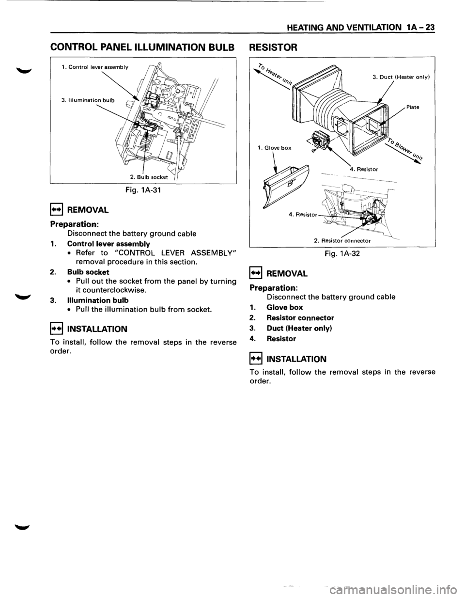
CONTROL PANEL ILLUMINATION BULB
1••1 REMOVAL
Preparation:
Fig. 1A-31
Disconnect
the battery ground cable
1. Control lever assembly
• Refer to "CONTROL LEVER ASSEMBLY"
removal
procedure in this section.
2. Bulb socket
• Pull out the socket from the panel by turning
it counterclockwise.
3.
Illumination bulb
• Pull the illumination bulb from socket.
I••IINSTALLATION
To install, follow the removal steps in the reverse
order.
HEATING AND VENTILATION 1A-23
RESISTOR
1. Glove box
1••1 REMOVAL
Preparation:
3. Duct (Heater only)
Plate
2. Resistor connector
Fig. 1A-32
Disconnect the battery
ground cable
1. Glove box
2. Resistor connector
3. Duct (Heater only)
4. Resistor
I••IINSTALLATION
To install, follow the removal steps in the reverse
order.
Page 85 of 1928
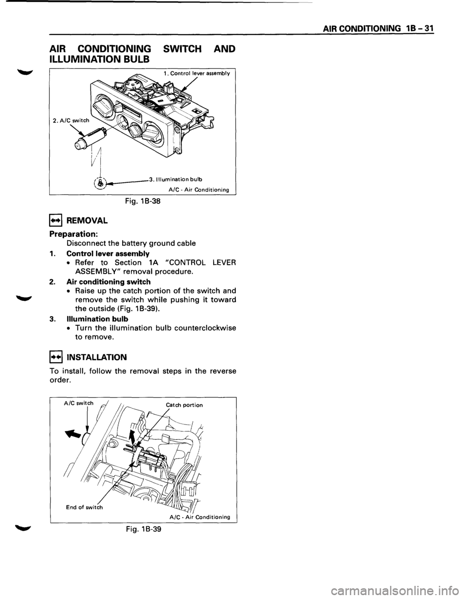
AIR CONDITIONING SWITCH AND
ILLUMINATION BULB
i-..---3. Illumination bulb
1++1 REMOVAL
Preparation:
Fig. 18-38
A/C -Air Conditioning
Disconnect the battery ground cable
1. Control lever assembly
• Refer to Section 1A "CONTROL LEVER
ASSEMBLY" removal procedure.
2. Air conditioning switch
• Raise up the catch portion of the switch and
remove the switch while pushing it toward
the outside (Fig. 1 B-39).
3. Illumination bulb
• Turn the illumination bulb counterclockwise
to remove.
I••IINSTALLATION
To install, follow the removal steps in the reverse
order.
End of switch
Fig. 18-39
AIR CONDITIONING 1 B -31
Page 96 of 1928
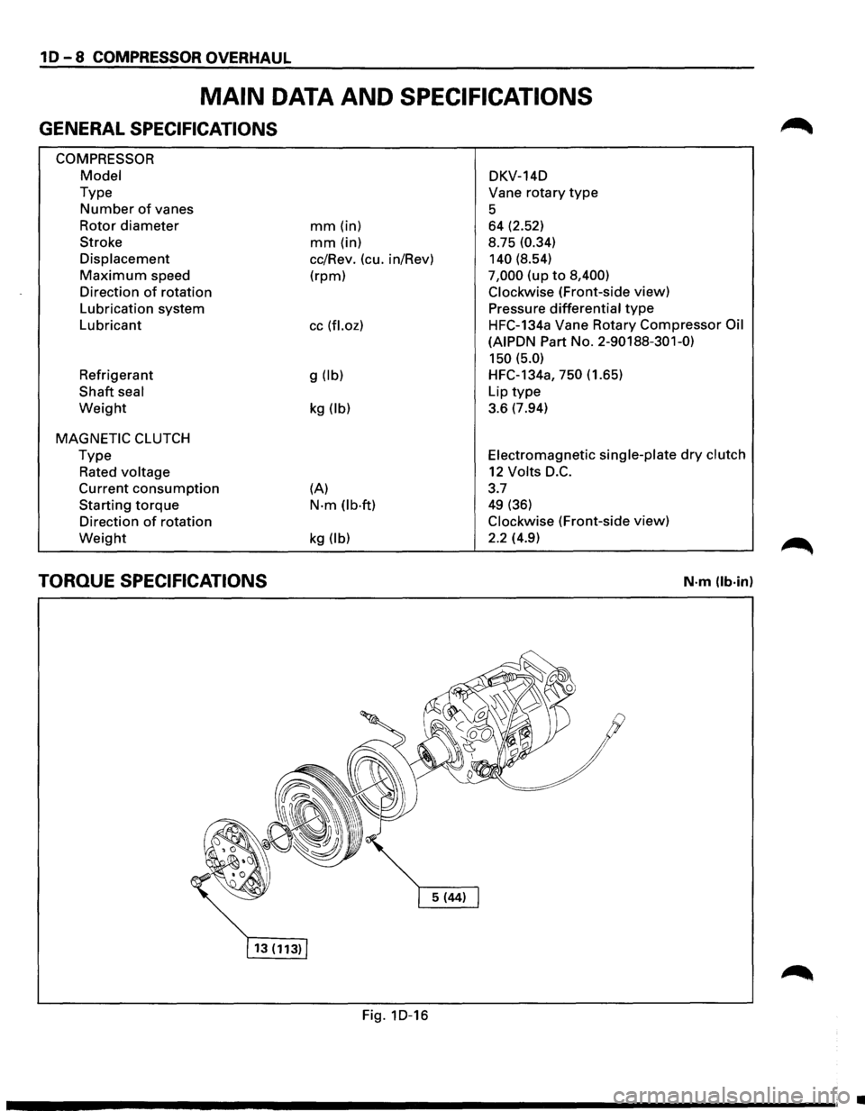
10-8 COMPRESSOR OVERHAUL
MAIN DATA AND SPECIFICATIONS
GENERAL SPECIFICATIONS
COMPRESSOR
Model
Type
Number of vanes
Rotor
diameter
Stroke
Displacement
Maximum speed
Direction
of rotation
Lubrication system
Lubricant
Refrigerant
Shaft seal
Weight
MAGNETIC CLUTCH
Type
Rated voltage
Current consumption
Starting torque
Direction of rotation
Weight
TORQUE SPECIFICATIONS
mm (in)
mm (in)
cc/Rev. (cu. in/Rev)
(rpm)
cc (fl.oz)
g (lb)
kg (lb)
(A)
N·m (lb·ft)
kg (lb)
Fig. 1D-16 DKV-14D
Vane
rotary type
5 64 (2.52)
8.75
(0.34)
140
(8.54)
7,000 (up to 8,400)
Clockwise
(Front-side view)
Pressure
differential type
HFC-134a Vane Rotary Compressor Oil
(AIPDN
Part No. 2-90188-301-0)
150 (5.0)
HFC-134a, 750 (1.65)
Lip
type
3.6 (7.94)
Electromagnetic single-plate dry clutch
12 Volts D.C.
3.7
49 (36)
Clockwise (Front-side view)
2.2 (4.9)
N·m (lb·in)
•
Page 143 of 1928
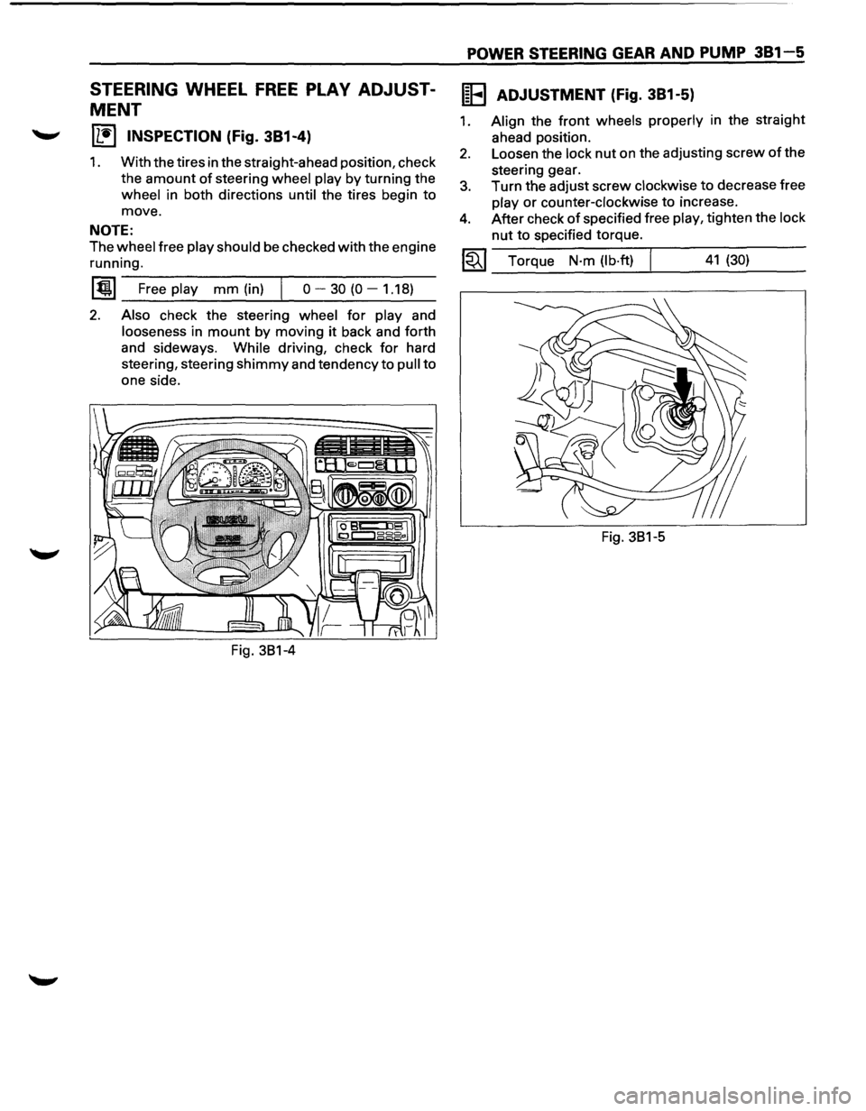
STEERING WHEEL FREE PLAY ADJUST
MENT
IL•I INSPECTION (Fig. 381-4)
1. With the tires in the straight-ahead position, check
the
amount of steering wheel play by turning the
wheel in both directions until the tires begin to
move.
NOTE:
The wheel free play should be checked with the engine
running.
~~~~F-r-ee--pl-ay---m-m--(in_)_,j--o----3-0-(0----1-.1-8~)-
2. Also check the steering wheel for play and
looseness in mount by moving it back and forth
and sideways.
While driving, check for hard
steering, steering
shimmy and tendency to pull to
one side.
POWER STEERING GEAR AND PUMP 381-5
IEEI ADJUSTMENT (Fig. 381-5)
1. Align the front wheels properly in the straight
ahead position.
2. Loosen the lock nut on the adjusting screw of the
steering gear.
3. Turn the adjust screw clockwise to decrease free
play or counter-clockwise to incre~se.
4. After check of specified free play, t1ghten the lock
nut to specified torque.
~~~ Torque N·m (lb·ft) I 41 (30)
Fig. 381-5
Page 148 of 1928
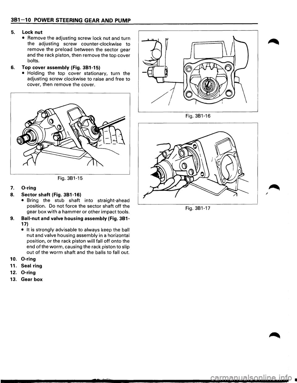
381-10 POWER STEERING GEAR AND PUMP
5. Lock nut
• Remove the adjusting screw lock nut and turn
the adjusting
screw counter-clockwise to
remove the preload between the sector gear
and the rack piston, then remove the
top cover
bolts.
6. Top cover assembly (Fig. 381-15)
• Holding the top cover stationary, turn the
adjusting screw
clockwise to raise and free to
cover, then remove the cover.
Fig. 381-15
7. 0-ring
8. Sector shaft (Fig. 381-16)
• Bring the stub shaft into straight-ahead
position. Do not force the sector shaft
off the
gear
box with a hammer or other impact tools.
9. Ball-nut and valve housing assembly (Fig. 381-
17)
• It is strongly advisable to always keep the ball
nut and valve housing assembly in a horizontal
position, or the rack piston will fall off onto the
end
of the worm, causing the rack piston to slip
out of the worm shaft and the balls to fall out.
10. 0-ring
11. Seal ring
12.
0-ring
13. Gear box
Fig. 381-16
Fig. 381-17
•
Page 160 of 1928
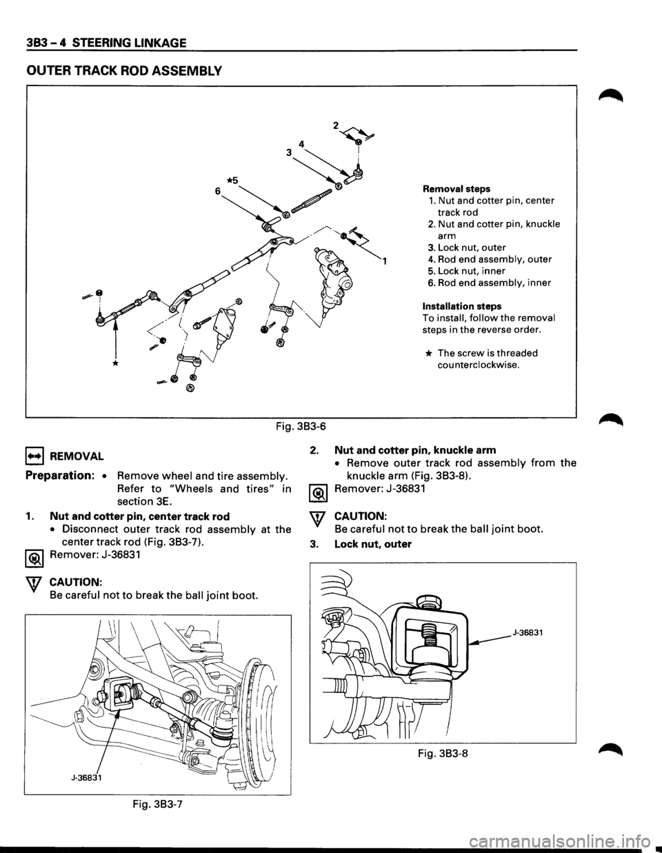
383 - 4 STEERING LINKAGE
OUTER TRACK ROD ASSEMBLY
1+•1 REMOVAL
Fig. 3B3-6
2.
Preparation: • Remove wheel and tire assembly.
Refer to "Wheels and tires" in
section
3E. ~
Removal steps
1. Nut and cotter pin, center
track rod
2. Nut and cotter pin, knuckle
arm
3. Lock nut, outer
4. Rod end assembly, outer
5. Lock nut, inner
6. Rod end assembly, inner
Installation steps
To install, follow the removal
steps in the reverse order.
* The screw is threaded
counterclockwise.
Nut and cotter pin, knuckle arm
• Remove outer track rod assembly from the
knuckle arm (Fig. 3B3-8).
Remover: J-36831
1. Nut and cotter pin, center track rod
• Disconnect outer track rod assembly at the
center track rod (Fig. 3B3-7).
'\f CAUTION:
Be careful not to break the ball joint boot.
3. Lock nut, outer Remover: J-36831
CAUTION:
Be careful not to break the ball joint boot.
J-36831
Fig. 3B3-8
Fig. 3B3-7
Page 161 of 1928
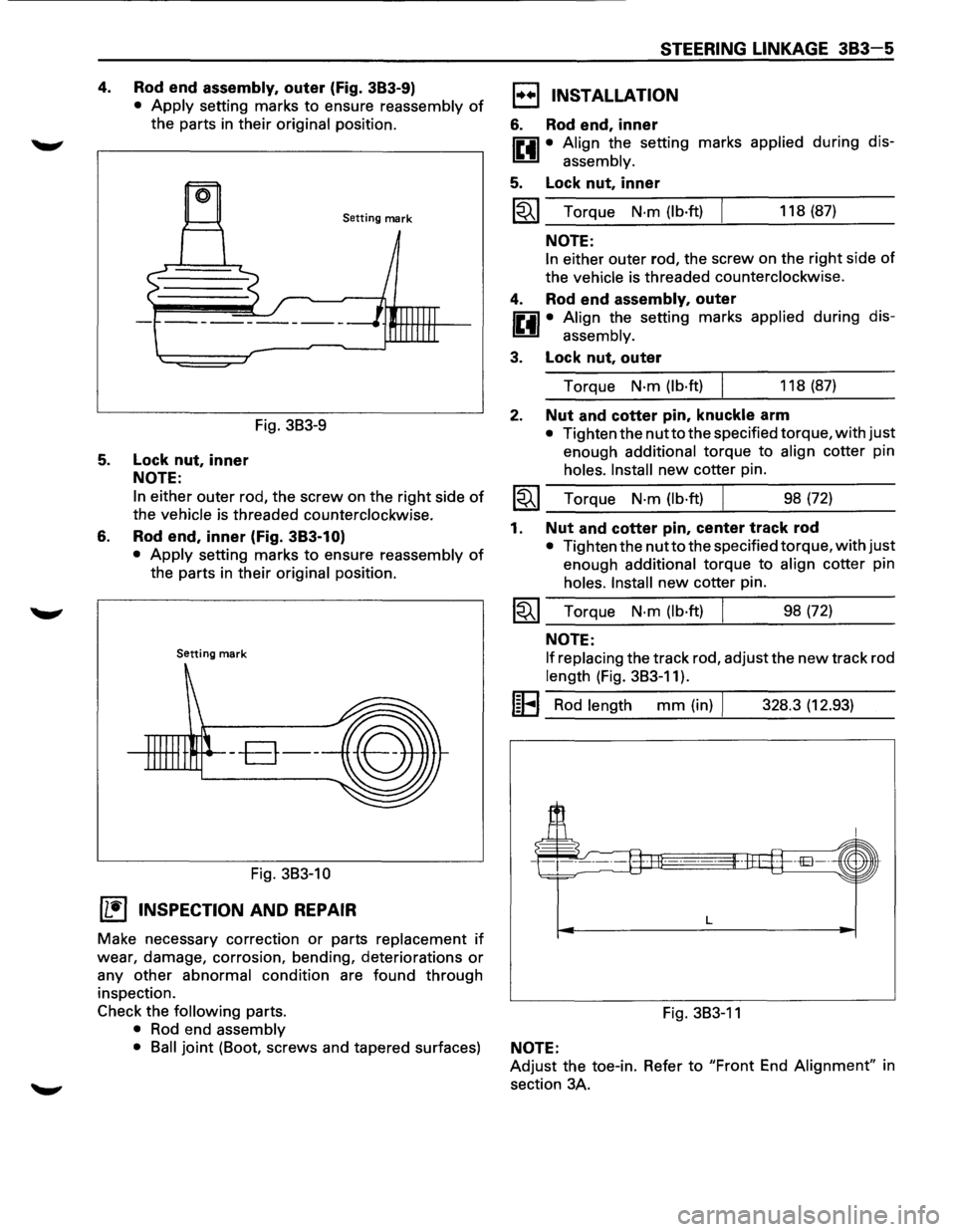
4. Rod end assembly, outer (Fig. 383-9)
• Apply setting marks to ensure reassembly of
the parts in their original position.
Setting mark
Fig. 3B3-9
5. Lock nut, inner
NOTE:
6.
In either outer rod, the screw on the right side of
the vehicle is threaded counterclockwise.
Rod end, inner (Fig. 383-1 O)
• Apply setting marks to ensure reassembly of
the parts in their original position.
Setting mark
--B--
Fig. 3B3-10
(1!] INSPECTION AND REPAIR
Make necessary correction or parts replacement if
wear, damage, corrosion, bending, deteriorations or
any other abnormal condition are found through
inspection.
Check the
following parts.
• Rod end assembly
STEERING LINKAGE 383-5
1••1 INSTALLATION
6. Rod end, inner
IP.il • Align the setting marks applied during dis-
~ assembly.
5. Lock nut, inner
~~~ Torque N·m (lb·ft) 118 (87)
NOTE:
In either outer rod, the screw on the right side of
the vehicle is threaded counterclockwise.
4. Rod end assembly, outer
IP.il • Align the setting marks applied during dis-
~ assembly.
3. Lock nut, outer
Torque N·m (lb·ft) 118 (87)
2. Nut and cotter pin, knuckle arm
• Tighten the nutto the specified torque, with just
enough additional torque to align cotter pin
holes. Install new cotter pin.
~~~ Torque N·m (lb·ft) ___ ______._ ___ _ 98 (72)
1. Nut and cotter pin, center track rod
• Tighten the nutto the specified torque, with just
enough additional torque to align cotter pin
holes. Install new cotter pin.
~~~ Torque N·m (lb·ft) 98 (72)
NOTE:
If replacing
the track rod, adjust the new track rod
length (Fig. 3B3-11).
I~EI Rod length mm (in) I 328.3 (12.93)
L
Fig. 3B3-11
• Ball joint (Boot, screws and tapered surfaces) NOTE:
Adjust the toe-in. Refer to "Front End Alignment" in
section 3A.
Page 219 of 1928
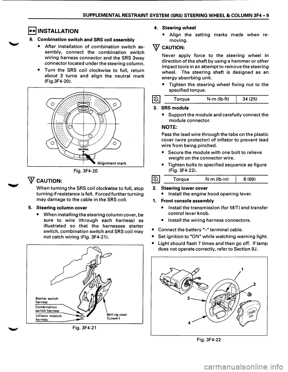
SUPPLEMENTAL RESTRAINT SYSTEM (SRS) STEERING WHEEL & COLUMN 3F4-9
B INSTALLATION
6. Combination switch and SRS coil assembly
•
After installation of combination switch as
sembly, connect the combination switch
wiring harness connector and the SRS 3way
connector located under the steering column.
•
Turn the SRS coil clockwise to full, return
about 3
turns and align the neutral mark
(Fig.3F4-20).
Alignment mark
Fig. 3F4-20
WcAUTION:
When turning the SRS coil clockwise to full, stop
turning if resistance is felt. Forced further turning
may damage to the cable in the SRS coil.
5. Steering column cover
• When installing the steering column cover, be
sure
to wire (through each harness) as
illustrated so that the harnesses starter
switch,
combination switch and SRS coil may
not catch wiring (Fig. 3F4-21 ).
Starter switch
harness
Combination switch harness
Inflator module harness
Fig. 3F4-21
4. Steering wheel
• Align the setting marks made when re
moving.
W CAUTION:
Never apply force to the steering wheel in
direction
of the shaft by using a hammer or other
impact tools in an attempt to remove the steering
wheel. The steering shaft is designed as an
energy absorbing unit.
• Tighten the steering wheel fixing nut to the
specified torque.
Torque
N·m (lb-ft) 34 (25)
3. SRS module
• Support the module and carefully connect the
module connector.
NOTE:
Pass the lead wire through the tabs on the plastic
cover (wire protector) of inflator to prevent lead
wire from being pinched.
• Secure the module with one bolt to relieve
weight on the connector wire.
• Tighten bolts to specified sequence as figure
(Fig. 3F4-22).
Torque
N·m (lb·in) 8 (69)
2. Steering lower cover
• Install the engine hood opening lever.
1. Front console assembly
• Install
the transmission (for MfT) and transfer
control lever knob.
• Install the wiring harness connectors.
• Connect the battery "-"terminal cable.
• Set
ignition to ·oN" while watching warning light.
•
Light should flash 7 times and then go off. If lamp
does not operate correctly, refer to Section 9J.
Fig. 3F4-22
Page 221 of 1928
SUPPLEMENTAL RESTRAINT SYSTEM (SRS) STEERING WHEEL & COLUMN 3F4-11
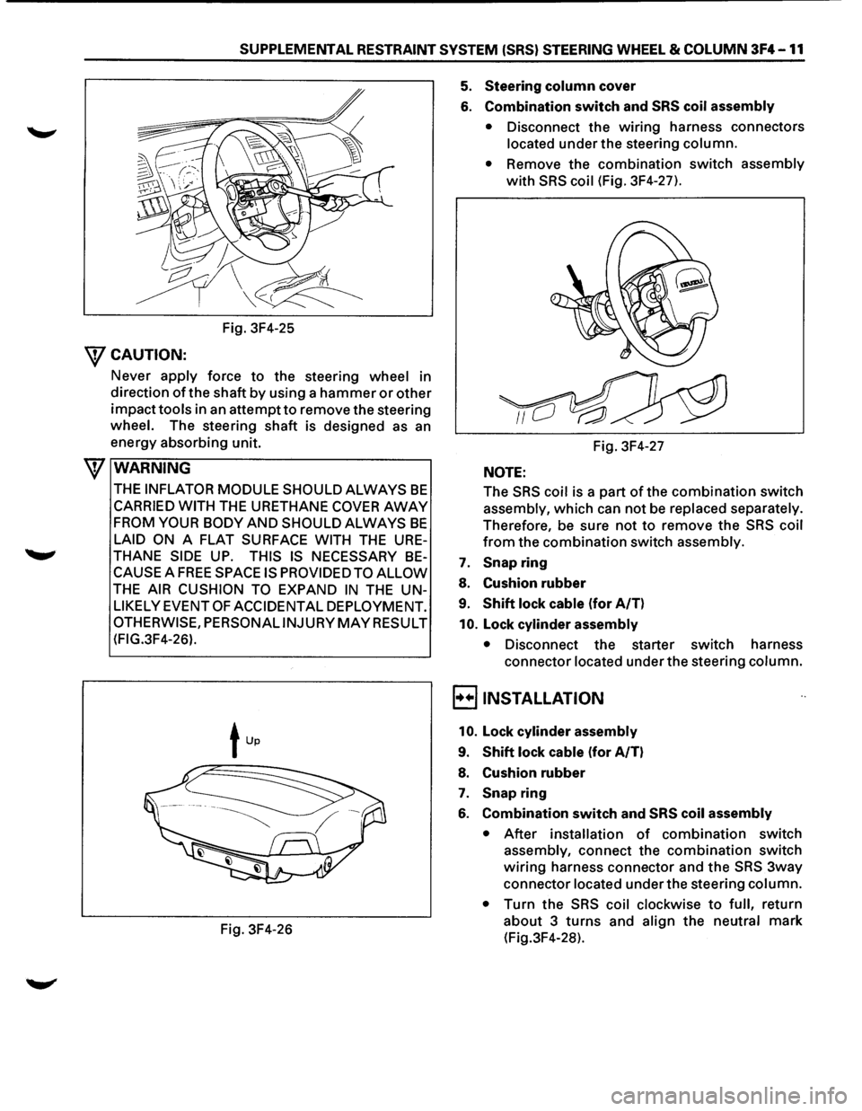
Fig. 3F4-25
WCAUTION:
Never apply force to the steering wheel in
direction
of the shaft by using a hammer or other
impacttools in an attempt to remove the steering
wheel. The steering shaft is designed as an
energy absorbing unit.
\f WARNING
THE INFLATOR MODULE SHOULD ALWAYS BE
CARRIED WITH THE URETHANE COVER AWAY
FROM YOUR BODY AND SHOULD ALWAYS BE
LAID ON A FLAT SURFACE WITH THE URE
THANE SIDE UP. THIS IS NECESSARY BE
CAUSE A FREE SPACE IS PROVIDED TO ALLOW
THE AIR CUSHION TO EXPAND IN THE UN
LIKELY EVENT OF ACCIDENTAL DEPLOYMENT.
OTHERWISE, PERSONALINJURY MAY RESULT
(FIG.3F4-26).
Fig. 3F4-26
5. Steering column cover
6. Combination switch and SRS coil assembly
• Disconnect the wiring harness connectors
located under the steering column.
•
Remove the combination switch assembly
with SRS coil (Fig. 3F4-27).
Fig. 3F4-27
NOTE:
The
SRS coil is a part of the combination switch
assembly, which can not be
replaced separately.
Therefore, be sure not
to remove the SRS coil
from the combination switch assembly.
7. Snapring
8. Cushion rubber
9. Shift lock cable (for A/T)
10. Lock cylinder assembly
• Disconnect the starter switch harness
connector
located under the steering column.
E) INSTALLATION
10. Lock cylinder assembly
9. Shift lock cable (for A/T)
8. Cushion rubber
7. Snap ring
6. Combination switch and SRS coil assembly
• After installation of combination switch
assembly, connect the combination switch
wiring harness connector and the SRS 3way
connector
located under the steering column.
•
Turn the SRS coil clockwise to full, return
about 3
turns and align the neutral mark
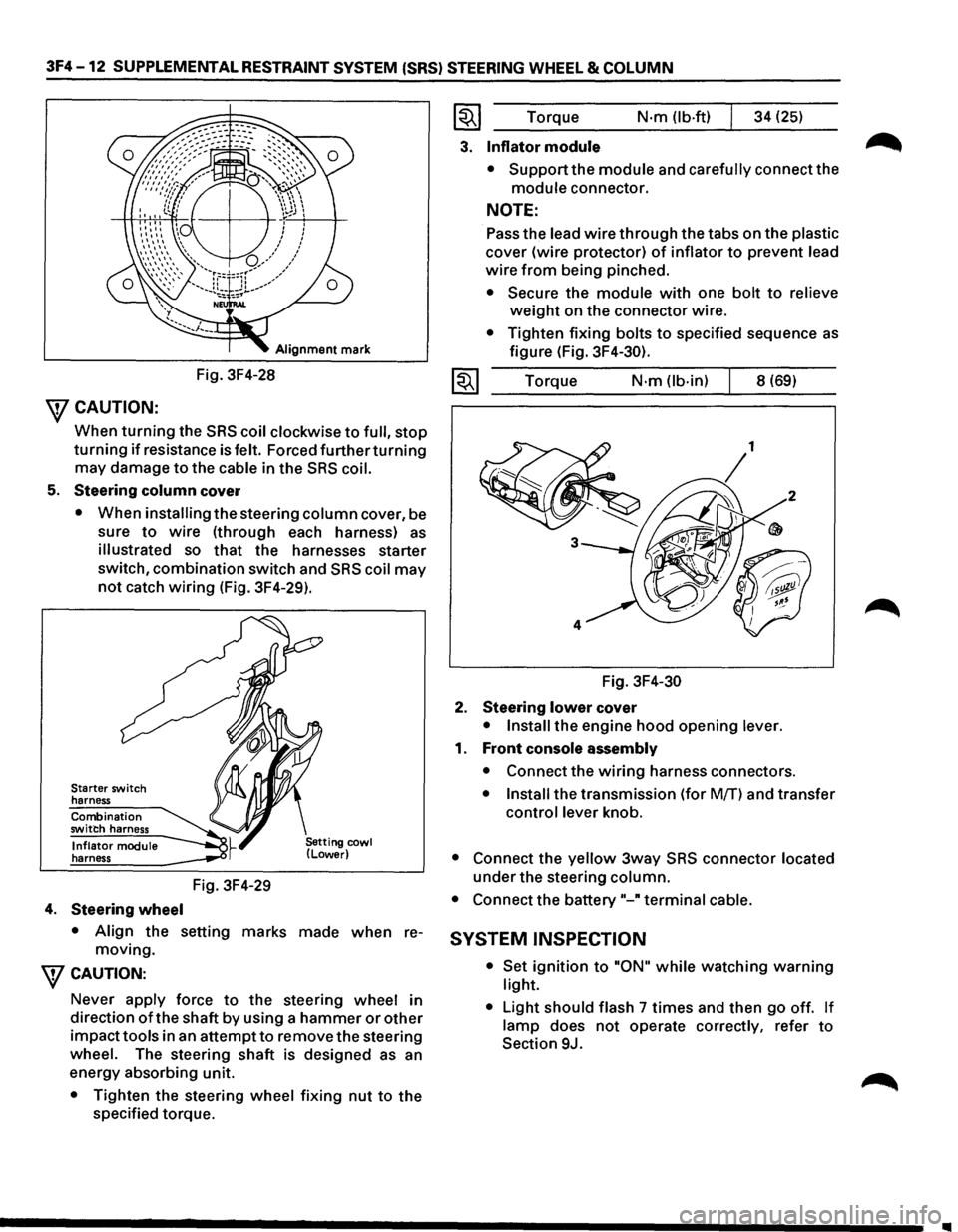
(Fig.3F4-28).
Page 222 of 1928
3F4 -12 SUPPLEMENTAL RESTRAINT SYSTEM (SRS) STEERING WHEEL & COLUMN
Alignment mark
Fig. 3F4-28
\fCAUTION:
When turning the SRS coil clockwise to full, stop
turning if resistance is felt. Forced further turning
may damage to the cable in the SRS coil.
5. Steering column cover
• When installing the steering column cover, be
sure
to wire (through each harness) as
illustrated so that the harnesses starter
switch,
combination switch and SRS coil may
not catch wiring (Fig. 3F4-29).
Starter switch
harness
Combination
switch harness
Inflator module
harness
4. Steering wheel
Fig. 3F4-29
• Align the setting marks made when re
moving.
\fCAUTION:
Never apply force to the steering wheel in
direction
of the shaft by using a hammer or other
impacttools in an attemptto remove the steering
wheel. The steering shaft is designed as an
energy absorbing unit.
• Tighten the steering wheel fixing nut to the
specified torque.
~~~ Torque N·m (lb-ft) 34 (25)
3. Inflator module
• Support the module and carefully connect the
module connector.
NOTE:
Pass the lead wire through the tabs on the plastic
cover (wire protector) of inflator to prevent lead
wire from being pinched.
• Secure the module with one bolt to relieve
weight on the connector wire.
• Tighten fixing bolts to specified sequence as
figure (Fig. 3F4-30).
1~1 Torque N·m (lb-in) 8 (69)
Fig.
3F4-30
2. Steering lower cover
• Install the engine hood opening lever.
1. Front console assembly
• Connect the wiring harness connectors.
• Install the transmission (for Mff) and transfer
control lever knob.
• Connect the yellow 3way SRS connector located
under the steering column.
• Connect the battery"-" terminal cable.
SYSTEM INSPECTION
• Set ignition to "ON" while watching warning
light.
•
Light should flash 7 times and then go off. If
lamp does not operate correctly, refer to
Section 9J.