change time ISUZU TROOPER 1995 Owner's Guide
[x] Cancel search | Manufacturer: ISUZU, Model Year: 1995, Model line: TROOPER, Model: ISUZU TROOPER 1995Pages: 1928
Page 992 of 1928
7A-120 AUTOMATIC TRANSMISSION (4L30-E)
DIAGNOSTIC
TROUBLE CODE (DTC) 51
ENGINE COOLANT SWITCH SHORT TO GROUND, PLUS OR OPEN
This DTC does NOT flash the CHECK TRANS
indicator and does NOT set the BACKUP MODE.
Circuit Description:
• The Engine Coolant Temperature is measured by
a sensor in the coolant system. This information
is used by the Engine Control Module (ECM) for
the engine. The ECM provides the information:
Engine Warm to the Transmission Control
Module (TCM) when the ECM measures a
temperature
higher than 70°C (158°F).
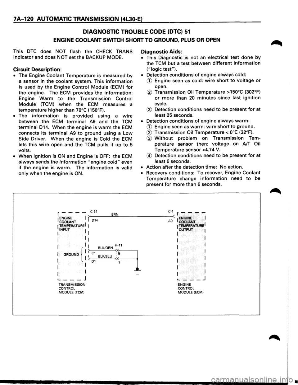
• The information is provided using a wire
between the ECM terminal A9 and the TCM
terminal D14. When the engine is warm the ECM
connects its terminal A9 to ground using a Low
Side Driver. When the engine is Cold the ECM
lets this wire open and the TCM pulls it up to 5
volts.
•
When Ignition is ON and Engine is OFF: the ECM
always sends the information "engine cold" even
if the engine is warm. The information is valid
only when the engine is ON.
Diagnostic Aids:
• This Diagnostic is not an electrical test done by
the TCM but a test between different information
("logic test").
• Detection conditions of engine always cold:
CD Engine! seen as cold: wire short to voltage or
open.
@ Transmission Oil Temperature >150°C (302°F)
or more than 20 minutes since last ignition
cycle.
@ Detection conditions need to be present for at
least 25 seconds.
• Detection conditions of engine always warm:
CD Engine! seen as warm: wire short to ground.
@ Transmission Oil Temperature< ooc (32°F).
@ Without problem on Transmission Tem
perature sensor then:
voltage on AfT Oil
Temperature sensor <4.74 V.
@ Detection conditions need to be present for at
least 6 seconds.
• Action after the detection time: No action.
• Recovery conditions: To recover, Engine Coolant
Temperature change information need to be
present
for more than 6 seconds.
r - - - -C·91 BRN C-1 r - - - -
I ~~~ENT I f,_D_1_4 __ ~.!__--------~-: I ~NGt~~ I
1 teMPERAtuRE I 1
1 t=R'ATJJRel
I INPUT I I I OUTP\:IT l
I 1
1 I I
I I I H-11 I l
I
GROUND 11 ? C1 BLKJORN ~9 I I I I BLKJBLU ( 1 I > o1 I
I I 1 I I
I I I I
~---J ~---J TRANSMISSION ENGINE
CONTROL CONTROL
MODULE
(TCM) MODULE (ECM)
•
Page 1004 of 1928
7A-132 AUTOMATIC TRANSMISSION (4L30-E)
DIAGNOSTIC TROUBLE CODE (DTC) 61
GEAR ERROR
This DTC flashes the CHECK TRANS indicator and
sets the BACKUP MODE.
Circuit Description:
• The Transmission Control Module (TCM) is
calculating the slippage of the Converter and
transmission based upon the Engine Speed, the
Output Speed and the current gear ratio.
• The slippage of the converter at a high enough
engine speed is low. Then the transmission
should not slip more than a given value when
there is no shift.
Diagnostic Aids:
• This Diagnostic is not an electrical test done by
the TCM but a test between different information
("logic test").
• Detection conditions:
CD Engine Speed > 3500 RPM
@ Using the ratio of the current gear the
Converter Slippage is calculated based upon
the engine speed and the output speed. This
slippage must be more than:
528
RPM in 4th gear
536 RPM in 3rd gear
556 RPM in 2nd gear
595 RPM in 1st gear
@ No malfunction: Engine Speed (DTC13).
Output Speed (DTC11 ). Downshift Protection
(DTC62).
@ The last change of shift solenoid was more
than 3 seconds ago.
® The conditions need to be present for at least
5.5 seconds.
• Action after the detection time: BACKUP MODE.
•
Recovery conditions: To recover, do an IGNITION
CYCLE.
NOTE:
The TCC slip data is a calculated value, and not an
accurate one.
This value should be used to see if the TCC is
engaged or not.
•
Page 1006 of 1928
7A-134 AUTOMATIC TRANSMISSION (4L30-E)
DIAGNOSTIC TROUBLE CODE (DTC) 62
DOWNSHIFT PROTECTION
This DTC flashes the CHECK TRANS indicator and
sets the
BACKUP MODE.
Circuit Description:
• The output speed information is used to
determine if the transmission has to upshift or
downshift.
• If this information suddenly changes due to an
open circuit or some electrical interference the
transmission
would downshift.
• To avoid this the Transmission Control Module
(TCM) is constantly checking the variations of the
Output Speed. If this variation is too great (too
much decrease
or increase) DTC62 is set. This
variation is taken into
amount only when the
output speed is more than : 90 KPH.
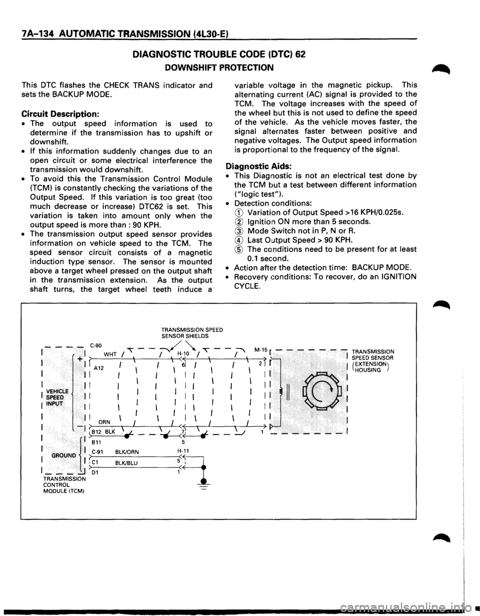
• The transmission output speed sensor provides
information on vehicle speed to the TCM. The
speed sensor circuit consists
of a magnetic
induction
type sensor. The sensor is mounted
above a target wheel pressed on the output shaft
in the transmission extension. As the
output
shaft turns, the target wheel teeth induce a
TRANSMISSION SPEED SENSOR SHIELDS
variable voltage in the magnetic pickup. This
alternating current (AC) signal is provided to the
TCM. The
voltage increases with the speed of
the wheel but this is not used to define the speed
of the vehicle. As the vehicle moves faster, the
signal alternates faster between positive and
negative
voltages. The Output speed information
is proportiional to the frequency of the signal.
Diagnostic Aids:
• This Diagnostic is not an electrical test done by
the TCM but a test between different information
("logic test").
• Detection conditions:
G) Variation of Output Speed >16 KPH/0.025s.
@ Ignition ON more than 5 seconds.
@ Mode Switch not in P, N or R.
@ Last Output Speed > 90 KPH.
@ The conditions need to be present for at least
0.1 second.
• Action after the detection time: BACKUP MODE.
•
Recovery Gonditions: To recover, do an IGNITION
CYCLE.
- - - -C-90 / " I ,---:-"'\. '-. ~---+I WHT I I I I ~-10 I 'I I 'I M-1
5 r - - - - - - -TRANSMISSION ) f I SPEED SENSOR I . I f A 12 I I I I ~ I I I I
I II I I I I I I I I I
I II I I I I 1 I I
~~~~rie II I Ill I I
IINPUT II I I I I
1 1 1 I l I I I I -? ORN I I < I I
I l: ):~~ BLK \~ __ ~~ __ ~
I GROUNO I C-91 BLK/ORN H-11
I I I C1 BLK/BLU ~ 9_ I ____ I D1
TRANSMISSION
CONTROL MODULE (TCM)
2 I I (EXTENSION)
: : .·(C},h.·.. ,.·, .. ·.,· .. : HOUSING
II II ·<;',~ . I
I I . 'I ' . . I
I I I
) I> 1 ________ I
•
Page 1027 of 1928
... ......,.
AUTOMATIC TRANSMISSION (4L30-E) 7A-155
ON-VEHICLE SERVICE
CHECKING TRANSMISSION FLUID
LEVEL
1. Park the vehicle on level ground.
2. Apply the parking brake.
3. Place the automatic transmission in "Park" and
start the engine.
Allow the engine to idle for
two minutes.
4. With the brakes applied, move the shifter lever
through all the gear ranges, ending in "Park".
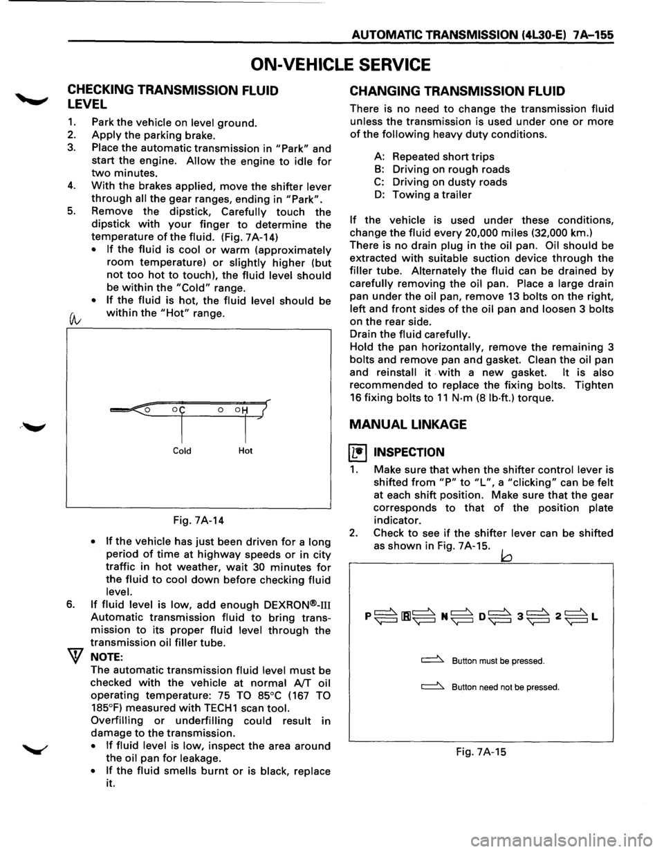
5. Remove the dipstick, Carefully touch the
dipstick with your finger to determine the
temperature of the fluid. (Fig. 7A-14)
• If the fluid is cool or warm (approximately
room temperature) or slightly higher (but
not too hot to touch), the fluid level should
be within the "Cold" range.
• If the fluid is hot, the fluid level should be
(A; within the "Hot" range.
6.
Cold Hot
Fig. 7A-14
• If the vehicle has just been driven for a long
period of time at highway speeds or in city
traffic in hot weather, wait 30 minutes for
the fluid to cool down before checking fluid
level.
If fluid level is low, add enough DEXRON®-m
Automatic transmission fluid to bring trans
mission
to its proper fluid level through the
transmission oil filler tube.
NOTE:
The automatic transmission fluid level must be
checked
with the vehicle at normal AfT oil
operating temperature: 75 TO 85°C (167 TO
185°F)
measured with TECH1 scan tool.
Overfilling or underfilling could result in
damage
to the transmission.
• If fluid level is low, inspect the area around
the oil pan for leakage.
•
If the fluid smells burnt or is black, replace
it.
CHANGING TRANSMISSION FLUID
There is no need to change the transmission fluid
unless the transmission is used under one or more
of the following heavy duty conditions.
A: Repeated
short trips
B: Driving on rough roads
C: Driving on dusty roads
D: Towing a trailer
If the vehicle is used under these conditions,
change the fluid every 20,000 miles (32,000 km.)
There is
no drain plug in the oil pan. Oil should be
extracted
with suitable suction device through the
filler tube. Alternately the fluid can be drained by
carefully removing the oil pan. Place a large drain
pan
under the oil pan, remove 13 bolts on the right,
left and front sides of the oil pan and loosen 3 bolts
on the rear side.
Drain
the fluid carefully.
Hold
the pan horizontally, remove the remaining 3
bolts and remove pan and gasket. Clean the oil pan
and
reinstall it . with a new gasket. It is also
recommended to replace the fixing bolts. Tighten
16 fixing bolts to 11 N·m (8 lb·ft.) torque.
MANUAL LINKAGE
~ INSPECTION
1. Make sure that when the shifter control lever is
shifted
from "P" to "L", a "clicking" can be felt
at each shift position. Make sure that the gear
corresponds
to that of the position plate
indicator.
2. Check to see if the shifter lever can be shifted
as
shown in Fig. 7A-15. jQ
~ Button must be pressed.
~ Button need not be pressed.
Fig. 7A-15
Page 1237 of 1928
CHASSIS ELECTRICAL 8-47
ENGINE CONTROL MODULE (ECM)
GENERAL DESCRIPTION
The ECM is used to control the fuel system of the
vehicle, especially in controlling the following items.
1. FUEL CONTROL
The amount of fuel and air sent into the combus
tion chamber is controlled by controlling the fuel
sent through the injector.
2. ELECTRIC FUEL PUMP (INSTALLED IN
THE FUEL TANK)
The in-tank fuel pump is controlled by the ECM.
When starter switch is turned on, the pump will
run for 2 seconds, then stop unless the engine is
cranking
or running.
3. IGNITION CONTROL
The system is controlled by the spark timing con
trol function of the ECM.
4. CIRCULATION OF EXHAUST GAS
The system controls the formation of NOx by
returning a small amount of exhaust gas to the
intake manifold
through the control valve.
'-" lAC: Idle air control
5. CONTROL OF AIR CONDITIONING (A/C)
For improved engine idling performance, the sys
tem controls the operation of the air conditioner
by regulating the
clutch operation ofthe A/C com
pressor in accordance
with changes in operation.
6. IDLE AIR CONTROL
The system controls the lAC Valve for the desired
idle speed in accordance
with changes in
operation.
7. DIAGNOSIS OF TROUBLES
When a sensor detects any signal that the ECM is
in
an abnormal condition, the ECM turns on the
malfunction
indicator (CHECK ENGINE) light in
the meter, and stores at the same
time the corre
sponding diagnostic
trouble code (DTC) in the
memory to indicate to which system or circuit the
trouble represented by the
DTC belongs.
The ECM inspection connector (data link connec
tor) is used
to retrieve the DTCs stored from the
ECM.
Refer to Section 6 "ENGINE DIAGNOSIS" for de
tails.
Page 1454 of 1928
8-264 CHASSIS ELECTRICAL
STARTER SWITCH
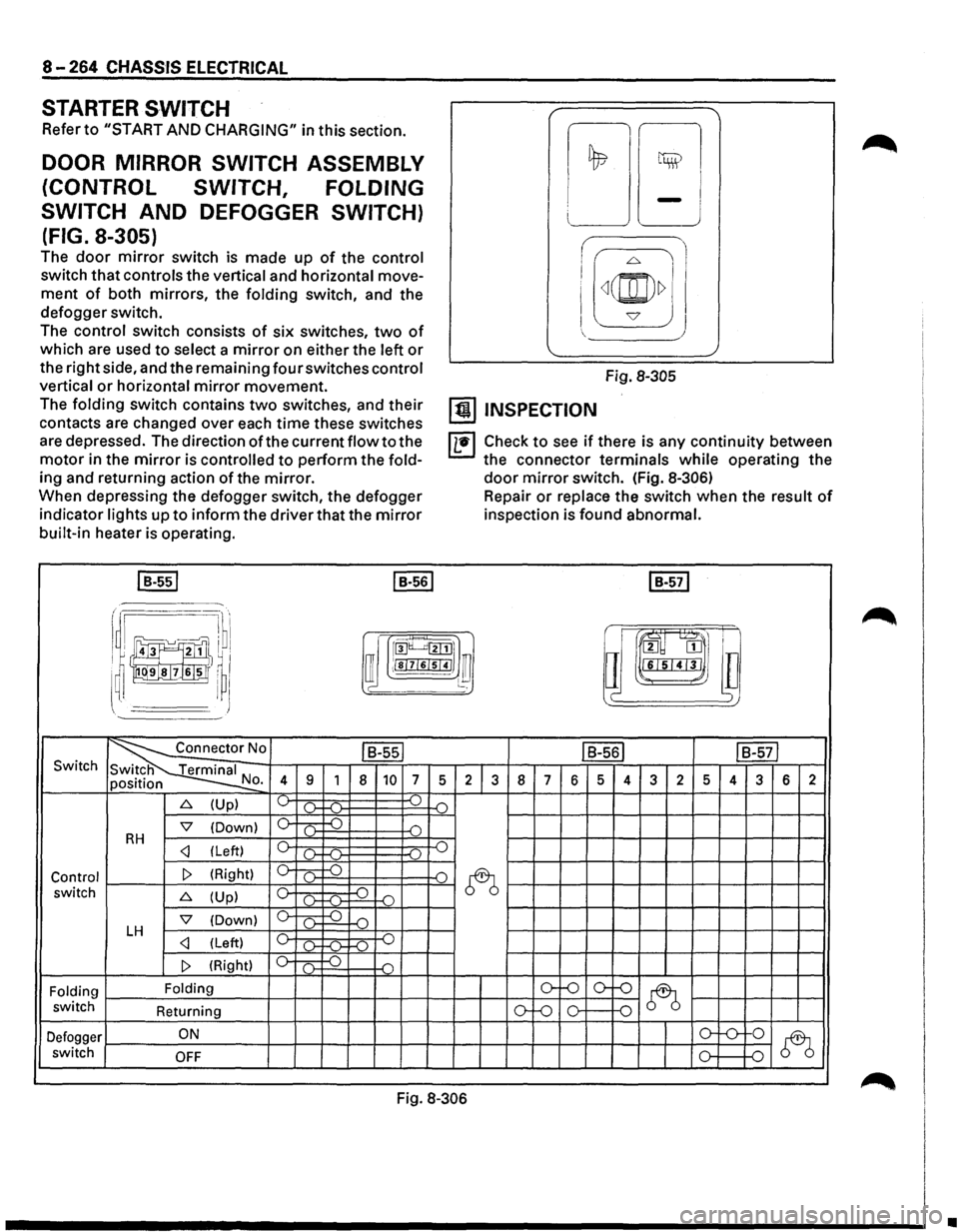
Refer to "START AND CHARGING" in this section.
DOOR MIRROR SWITCH ASSEMBLY
(CONTROL SWITCH, FOLDING
SWITCH
AND DEFOGGER SWITCH)
(FIG. 8-305)
The door mirror switch is made up of the control
switch that controls the vertical and horizontal move
ment of both mirrors, the folding switch, and the
defogger switch.
The control switch consists of six switches, two of
which are used to select a mirror on either the left or
the right side, and the remaining four switches control
vertical or horizontal mirror movement.
The folding switch contains two switches, and their
contacts are changed over each time these switches
are depressed. The direction of the current flow to the
motor in the mirror is controlled to perform the fold
ing and returning action of the mirror.
When depressing the defogger switch, the defogger
indicator lights up to inform the driver that the mirror
built-in heater is operating.
I B-551 I B-561
i I I
!;l ~
LJ -J
I
I[~(@)~] J
Fig. 8-305
[!) INSPECTION
IL•I Check to see if there is any continuity between
the connector terminals while operating the
door mirror switch. (Fig. 8-306)
Repair or replace the switch when the result of
inspection is found abnormal.
I B-571
r .·~·· I ~ru·l
~~J!]}I ~ rroo~~l]
i !)~~1,1
a m
I ~ I ffi ;!sl7l6lsl41 ~ l~ lll"L•I'J'I•J ~~~
~' I J )
~0 ls-ssl IB-561 IB-571 Switch
N 4 9 1 8 10 7 5 2 3 8 7 6 5 4 3 2 5 4 3 6 2 o.
6. (Up) ~ ).. ...( ) .(")
'7 (Down) 0 c .) D RH c _.)
~ switch 6. (Up) c ~ -o ()-f-(l-
'7 (Down) 0 ( ) D LH c _.)
Folding Folding o-f-0 o--()
~ switch
Returning ()-Lo 0 0
Defogger ON o-'-0-
0
~ switch OFF 0 D
Fig. 8-306
•
Page 1496 of 1928
8-306 CHASSIS ELECTRICAL
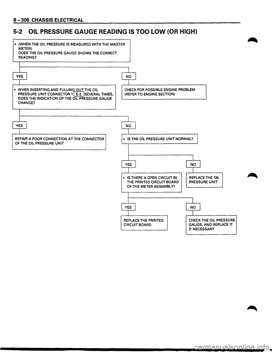
5-2 OIL PRESSURE GAUGE READING IS TOO LOW (OR HIGH)
• (WHEN THE OIL PRESSURE IS MEASURED WITH THE MASTER METER)
DOES THE OIL PRESSURE GAUGE SHOWS THE CORRECT READING?
I
I
YES I NO I
I
• WHEN INSERTING AND PULLING OUT THE OIL CHECK FOR POSSIBLE ENGINE PROBLEM PRESSURE UNIT CONNECTOR 1 [IDSEVERAL TIMES, (REFER TO ENGINE SECTION) DOES THE INDICATION OF THE OIL PRESSURE GAUGE CHANGE?
I
I
YES I NO I
I
REPAIR A POOR CONNECTION AT THE CONNECTOR • IS THE OIL PRESSURE UNIT NORMAL? I OF THE OIL PRESSURE UNIT
I
YES J NO I
I
• IS THERE A OPEN CIRCUIT IN REPLACE THE OIL
THE PRINTED CIRCUIT BOARD PRESSURE UNIT
OF THE METER ASSEMBLY?
I
YES I NO I
I
REPLACE THE PRINTED CHECK THE OIL PRESSURE
CIRCUIT BOARD GAUGE, AND REPLACE IT
IF NECESSARY
Page 1630 of 1928
9J-6 Supplemental Restraint System <
COMPONENT DESCRIPTION
DERM
CAUTION: DO NOT OPEN THE DERM CASE FOR
ANY REASON. TOUCHING THE CONNECTOR PINS
OR SOLDERED COMPONENTS MAY CAUSE
ELECTROSTATIC DISCHARGE DAMAGE. REPAIR
OF A MALFUNCTIONING DERM IS BY
REPLACEMENT ONLY.
The DERM is designed to perform the following functions
in the SRS:
1. Energy Reserve- The DERM maintains two 36-Volt
Loop Reserve(36VLR) energy supplies to provide
deployment energy when the vehicle voltage is low
or lost in a frontal crash.
2. Malfunction Detection-The DERM performs
diagnostic monitoring of SRS electrical components.
3. Malfunction Recording- The DERM provides SRS
diagnostic trouble code information through a scan
tool.
4. Driver Notification- The DERM warns the vehicle
driver of SRS malfunctions by controlling the "AIR
BAG"
warning lamp.
5. Frontal Crash Recording- The DERM records the
SRS status during a frontal crash.
The DERM is connected to the
SRS wiring harness by
a
24-way connector. This harness connector uses a
shorting
clip across certain terminals in the contact area.
This shorting
clip connects the "AIR BAG" warning lamp
to ground when the DERM harness connector is
disconnected. This will cause the "AIR BAG" warning
lamp to come "ON" steady whenever the ignition switch
is at the RUN,BULB
TEST or START positions with the
DERM disconnected.
"AIR BAG"WARNING LAMP
Ignition voltage is applied to the "AIR BAG" warning lamp
when the ignition switch is at the RUN,BULB TEST or
START positions. The DERM controls the lamp by
providing ground with a
lamp driver. The "AIR BAG"
warning lamp is used in the SRS to do the following:
1. Verify lamp and DERM operation by flashing SEVEN
times when the ignition switch is first turned"ON".
2. Warn the vehicle driver of SRS electrical system
malfunctions which could potentially affect the
operation of the
SRS. These malfunctions could
result
in non-deployment in case of a frontal crash
or deployment for conditions less severe than
intended.
The "AIR BAG" warning lamp is the key to driver
notification of SRS malfunctions. For proper lamp
operation, refer to the "SRS Diagnostic System Check"
in this section.
DUAL POLE ARMING SENSOR ~
The dual pole arming sensor is a protective switch
located in the high side(power side) of the deployment
loops.
The dual pole arming sensor is calibrated to close
at low level velocity changes(lower than the
discriminating sensors).
This ensures that the
inflator modules are connected
directly to the "36 VLR" outputs of the DERM or "Ignition
1" voltage
when any discriminating sensor closes.
The dual pole arming sensor consists of: a sensing
element, two sets of normally open switch contacts,
diagnostic resistors and diodes. The sensing
element
closes
both sets of switch contacts when the velocity of
the
vehicle changes at a rate indicating a potential need
for
deployment.
Two of the diagnostic resistors are connected in parallel
with the switch contacts. This allows a small amount of
current to
flow through each of the deployment loops
during normal, non-deployment operation. This current
flow results in voltage drops across each component in
the
deployment loops. The DERM monitor these voltage
drops to detect circuit or component malfunctions. There
are two
additional diagnostic resistors within the dual
pole
arming sensor which allow the DERM to monitor the
voltage supplied to the high side ofthe deployment loops.
These monitored voltages are used by the diagnostic
logic of the DERM to make a more precise determination
of the
actual deployment loop malfunction. ~
The diodes within the dual pole arming sensor provide
isolation between the "36VLR" outputs of the DERM and
the
vehicle electrical system "Ignition 1" voltage. The
presence of the diodes prevents a direct continuity
measurement through the
dual pole arming sensor
resistors to
terminals"3","4" or "5".
DISCRIMINATING SENSORS
The discriminating sensors are protective switches wired
in parallel on the low side(ground side) of the deployment
loops.
These sensors are calibrated to close with velocity
changes which are severe enough to warrant
deployment.
The discriminating sensors consist of a sensing element
and normally open switch contacts when the vehicle
velocity changes are severe enough to warrant
deployment.
A diagnostic resistor is connected in parallel with the
switch contacts within the
LH forward discriminating
sensor and
RH forward discriminating sensor. These
parallel resistors supply the ground path for the current
passing through the
deployment loops during normal,
non-deployment operation. This current flow results in
voltage drops across each component within the
deployment loops. The DERM monitors these voltage
drops to detect circuit or component malfunctions.
II
Page 1632 of 1928
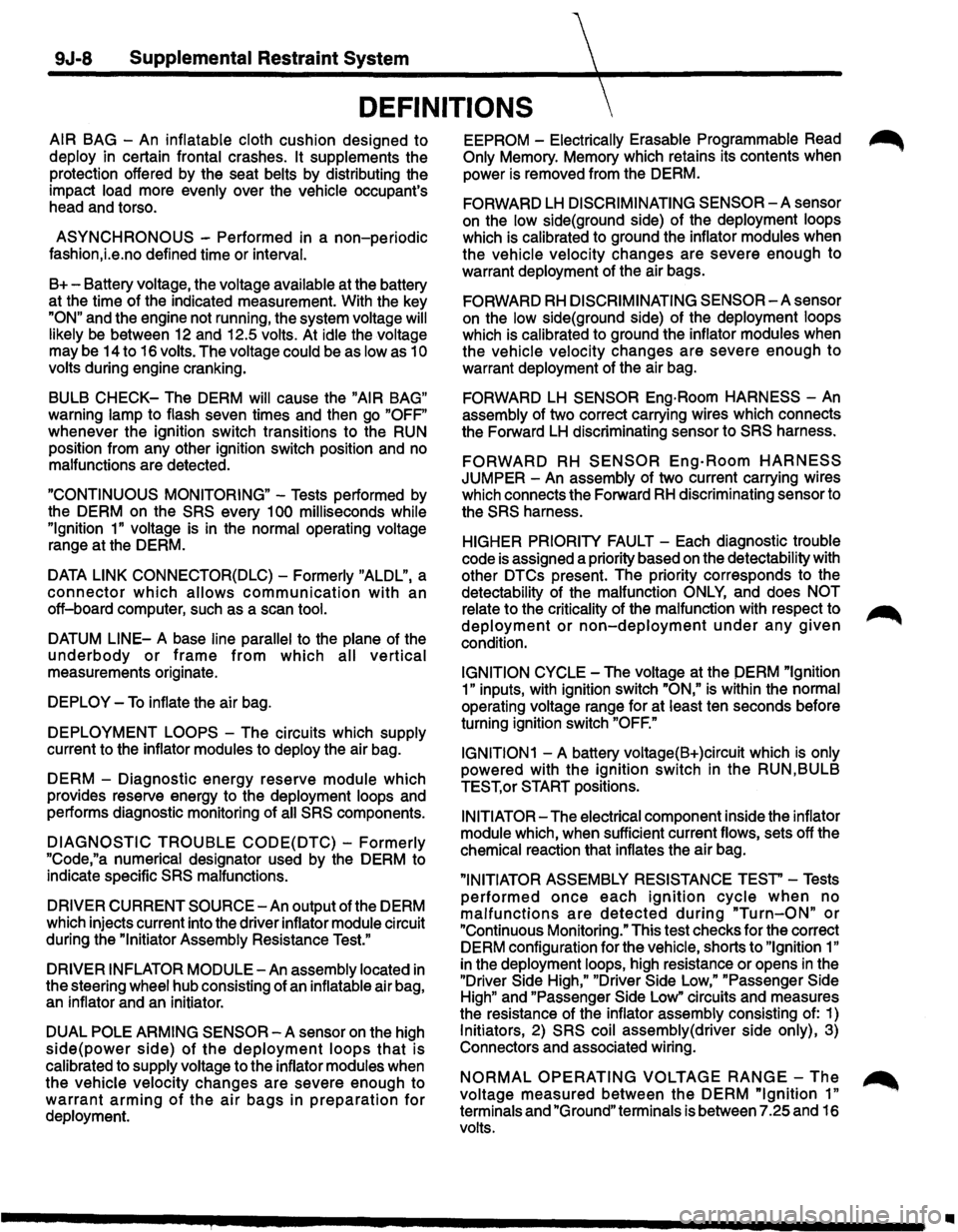
9J-8 Supplemental Restraint System
DEFINITIONS
AIR BAG -An inflatable cloth cushion designed to
deploy in certain frontal crashes. It supplements the
protection offered by the seat belts by distributing the
impact load more evenly over the vehicle occupant's
head and torso.
ASYNCHRONOUS -Performed in a non-periodic
fashion,i.e.no defined time or interval.
B+-Battery voltage, the voltage available at the battery
at the time of the indicated measurement. With the key
"ON" and the engine not running, the system voltage will
likely be between 12 and 12.5 volts. At idle the voltage
may be 14 to 16 volts. The voltage could be as low as 1
0
volts during engine cranking.
BULB
CHECK-The DERM will cause the "AIR BAG"
warning lamp to flash seven times and then go "OFF"
whenever the ignition switch transitions to the RUN
position from any other ignition switch position and no
malfunctions are detected.
"CONTINUOUS MONITORING"-Tests performed by
the DERM on the
SRS every 1 00 milliseconds while
"Ignition
1" voltage is in the normal operating voltage
range at the DERM.
DATA LINK CONNECTOR(DLC)-Formerly "ALDL'', a
connector which allows communication with an
off-board computer, such as a scan
tool.
DATUM LINE-A base line parallel to the plane of the
underbody or frame from which all vertical
measurements originate.
DEPLOY-To inflate the air bag.
DEPLOYMENT
LOOPS - The circuits which supply
current to the inflator modules to deploy the air bag.
DERM -Diagnostic
energy reserve module which
provides reserve energy to the deployment loops and
performs diagnostic monitoring of
all SRS components.
DIAGNOSTIC TROUBLE CODE(DTC) -Formerly
"Code,"a numerical designator used by the DERM to
indicate specific
SRS malfunctions.
DRIVER CURRENT SOURCE-An output of the DERM
which injects current into the driver inflator module circuit
during the "Initiator Assembly Resistance
Test."
DRIVER INFLATOR
MODULE-An assembly located in
the steering wheel hub consisting of an inflatable air bag,
an inflator and an initiator.
DUAL
POLE ARMING SENSOR-A sensor on the high
side(power side) of the deployment loops that is
calibrated to supply voltage to the inflator modules when
the vehicle velocity changes are severe enough to
warrant arming of the air bags in preparation for
deployment.
EEPROM -Electrically Erasable Programmable Read ~
Only Memory. Memory which retains its contents when
power
is removed from the DERM.
FORWARD LH DISCRIMINATING SENSOR-A sensor
on the low side(ground side) of the deployment loops
which is calibrated to ground the inflator modules when
the vehicle velocity changes are severe enough to
warrant deployment of the air bags.
FORWARD RH DISCRIMINATING SENSOR-A sensor
on the low side(ground side) of the deployment loops
which
is calibrated to ground the inflator modules when
the vehicle velocity changes are severe enough
to
warrant deployment of the air bag.
FORWARD LH SENSOR Eng-Room HARNESS-An
assembly of two correct carrying wires which connects
the Forward
LH discriminating sensor to SRS harness.
FORWARD RH SENSOR Eng-Room HARNESS
JUMPER-An assembly of two current carrying wires
which connects the Forward
RH discriminating sensor to
the
SRS harness.
HIGHER PRIORITY FAULT-Each diagnostic trouble
code
is assigned a priority based on the detectability with
other DTCs present. The priority corresponds to the
detectability of the malfunction ONLY, and does NOT
relate to the criticality of the malfunction with respect to ~
deployment or non-deployment under any given
condition.
IGNITION CYCLE -The voltage at the PERM "Ignition
1"
inputs, with ignition switch "ON," is within the normal
operating voltage range for at least ten seconds before
turning ignition switch
"OFF."
IGNITION1
-A battery voltage(B+)circuit which is only
powered with the ignition switch in the RUN,BULB
TEST,or START positions.
INITIATOR-The electrical component inside the inflator
module which, when sufficient current flows, sets off the
chemical reaction that inflates the air bag.
"INITIATOR ASSEMBLY RESISTANCE TEST"-Tests
performed once each ignition cycle when no
malfunctions are detected during "Turn-ON" or
"Continuous Monitoring." This test checks for the correct
DERM configuration for the vehicle, shorts to
"Ignition 1"
in the deployment loops, high resistance or opens in the
"Driver
Side High," "Driver Side Low," "Passenger Side
High"
and "Passenger Side Low" circuits and measures
the resistance of the inflator assembly consisting of: 1)
Initiators, 2) SRS coil assembly(driver side only), 3)
Connectors and associated wiring.
NORMAL OPERATING VOLTAGE RANGE-The ~
voltage measured between the DERM "Ignition 1" ·
terminals and "Ground" terminals is between 7.25 and 16
volts.
•
Page 1708 of 1928
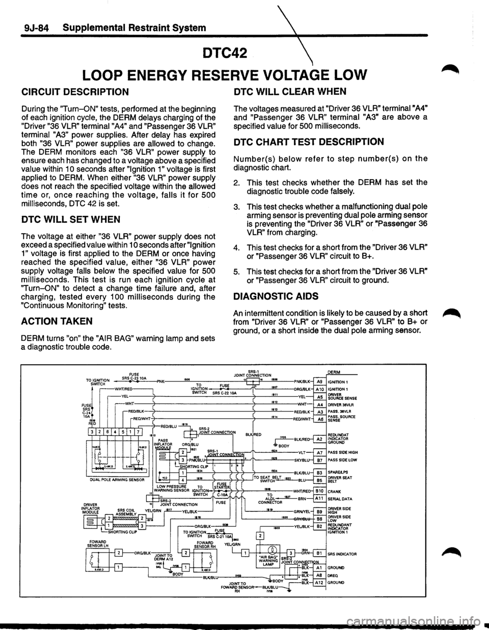
9J-84 Supplemental Restraint System
DTC42
LOOP ENERGY RESERVE VOLTAGE LOW
CIRCUIT DESCRIPTION
During the "Turn-ON" tests, performed at the beginning
of each ignition
cycle, the DERM delays charging of the
"Driver "36
VLR" terminal "A4" and "Passenger 36 VLR"
terminal
"A3" power supplies. After delay has expired
both "36
VLR" power supplies are allowed to change.
The DERM monitors each
"36 VLR" power supply to
ensure each has changed to a
voltage above a specified
value within 1 0 seconds after "Ignition 1" voltage is first
applied to DERM. When either "36 VLR" power supply
does not reach the specified voltage within the allowed
time or, once reaching the voltage, falls it for 500
milliseconds, DTC 42 is set.
DTC WILL SET WHEN
The voltage at either "36 VLR" power supply does not
exceed a specified
value within 10 seconds after "Ignition
1" voltage is first applied to the DERM or once having
reached the specified
value, either "36 VLR" power
supply voltage falls below the specified value for 500
milliseconds.
This test is run each ignition cycle at
"Turn-ON" to detect a change time failure and, after
charging, tested every
100 milliseconds during the
"Continuous Monitoring" tests.
ACTION TAKEN
DERM turns "on" the "AIR BAG" warning lamp and sets
a diagnostic
trouble code.
DTC WILL CLEAR WHEN
The voltages measured at "Driver 36 VLR" terminal "A4"
and "Passenger 36
VLR" terminal "A3" are above a
specified
value for 500 milliseconds.
DTC CHART TEST DESCRIPTION
Number(s) below refer to step number(s) on the
diagnostic chart.
2. This test checks whether the DERM has set the
diagnostic
trouble code falsely.
3. This test checks whether a malfunctioning dual pole
arming sensor is preventing dual pole arming sensor
is preventing the "Driver 36
VLR" or "Passenger 36
VLR" from charging.
4. This test checks for a short from the "Driver 36 VLR"
or "Passenger 36 VLR" circuit to 8+.
5. This test checks for a short from the "Driver 36 VLR"
or "Passenger 36 VLR" circuit to ground.
DIAGNOSTIC AIDS
An intermittent condition is likely to be caused by a short
from "Driver 36
VLR" or "Passenger 36 VLR" to B+ or
ground, or a short inside the
dual pole arming sensor.
SRS~1 JOINT CONNECTION IBOii 12 1G IGNITION 1
DRIVER 36VLR PASS.31VLR PASS. SOURCE SENSE
REDUNDAT INDICATOR GROUND
PASS SIDE HIGH PASS SIDE LOW
SPAREilPS
SERIAL DATA
DRIVER SIDE HIGH DRIVER SIDE LOW REDUNDANT INDICATOR IGNmON 1
1111