change time ISUZU TROOPER 1995 Workshop Manual
[x] Cancel search | Manufacturer: ISUZU, Model Year: 1995, Model line: TROOPER, Model: ISUZU TROOPER 1995Pages: 1928
Page 3 of 1928
•:1
SECTION TABLE OF CONTENTS
. GENERAL INFORMATION OA General Information OB Maintenance and Lubrication
WORKSHOP MANUAL
HEATING AND AIR CONDITIONING 1A Heating and Ventilation
1B Air Conditioning 1D Compressor Overhaul
TROOPER
FRAME, BUMPERS AND SHEET METAL
2A Frame 2B Bumpers
(UX) 2C Sheet Metal
STEERING, SUSPENSION, WHEELS AND TIRES
3 Diagnosis 3A Front End Alignment 3B1 Power Steering Gear and Pump 3B3 Steering Linkage 3C Front Suspension 3D Rear Suspension 3E Wheels and Tires 3F4 Supplemental Restraint System Steering Wheel
FOREWORD and Column
PROPELLER SHAFT AND AXLE 4A Propeller Shaft This manual includes special notes, important points, service 4B Rear Axle
data, precautions, etc. that are needed for the maintenance, 4C Front Driving Axle
adjustments, service, removal and installation of vehicle BRAKES components. 5A Hydraulic Brakes
·~ m rmation, illustrations and specifications contained in 5A1 Brake Booster System
.. _,. 5A2 Disc Brakes ~ this ma. ~-based D.fl the latest product information 5A3 Rear Wheei_Antilock Brake System (RWAL)
available at the tirrHHrl·publication. 5A4 4-wheel Antilock Brake System (ABS)
5C Parking Brakes All rights are reserved to make changes at any time without ENGINE notice. 6· Engine General Information Arrangement of the material is shown in the table of contents &A General Engine Mechanical
on the right-hand side of this page. A black spot on the first 6A1 3.2L VB Engine
page of each section can be seen on the edge of the book &B Engine Cooling
6C Engine Fuel below each section title. These point to a more detailed table &D Engine Electrical of contents preceding each section. 6D1 Battery 6D2 Cranking System
This manual applies to 1995 models. 6D3 Charging System 6D4-Ignition System 6E2. Driveability and Emissions 6F Engine Exhaust
TRANSMISSION 7A-Automatic Transmission (4L30·E) 7B Manual Transmission 7C Clutch 7D Transfer Case
8 CHASSIS ELECTRICAL
ACCESSORIES 9A Radio 9B Cruise Control 9J Supplemental Restraint System (SRS)-AIR BAG
10 BODY
APPENDIX A CONVERSION TABLES PUBLICATION NO. UXOO-WSM-L0001-00
APPENDIXB HYDRAULIC CIRCUIT DIAGRAM (Automatic Transmission)
© 1994 ISUZU MOTORS LIMITED
Page 21 of 1928
FLUID LEVEL CHECK
A fluid loss in any system (except windshield
washer) may indicate a problem. Repair the system
at once.
Engine
oil level -Check level and add if
necessary. The best time to check the engine oil
level is
when the oil is warm. After stopping the
engine with the vehicle on a level surface, wait a
few minutes for the oil to drain back to the oil pan.
Pull
out the oil level indicator (dipstick). Wipe it
clean and push the oil level indicator back down all
the
way. Pull out the oil level indicator, keeping the
tip down, and look at the oil level on it.
Add oil, if needed, to keep the oil level above
the
"ADD" mark and between the "ADD" and
"FULL" marks in the operating range area. Avoid
overfilling the engine since this may cause engine
damage. Push
the oil level indicator back down all
the
way after taking the reading.
If you check the oil level when the oil is cold, do
not run the engine first. The cold oil will not drain
back
to the pan fast enough to give a true oil level.
Engine coolant level and condition -Check
engine coolant level in the coolant reservoir and
add engine
coolant if necessary. Inspect the engine
coolant and replace it if dirty or rusty.
Windshield washer fluid level -Check washer
fluid level in reservoir and add if necessary.
Power steering system reservoir level-Check
and keep at
proper level.
Brake master cylinder reservoir level -Check
fluid. Keep fluid at proper level. A low fluid level
can indicate
worn disc brake pads which may need
to be serviced.
Hydraulic clutch system -Check fluid l~vel in
the reservoir.
Add fluid as required.
Battery fluid level -Check fluid level in the
battery.
FLUID LEAK CHECK
Check for fuel, water, oil or other fluid leaks by
looking at the surface beneath the vehicle after it
has been parked for a while. Water dripping from
the air conditioning system after use is normal. If
you notice gasoline fumes or fluid at any time,
locate the source and correct it at once.
ENGINE OIL AND OIL FILTER
REPLACEMENT
Always use API SE, SF, SG, SH or ILSAC GF-1
quality oils of the proper viscosity.
When choosing an oil, consider the range of
temperatures the car will be operated in before the
next oil change. Then, select the recommended oil
viscosity
from the chart (Fig. OB-1).
Always change the oil and the oil filter as soon as
possible after driving in a dust storm.
MAINTENANCE AND LUBRICATION OB-5
ENGINE COOLING SYSTEM INSPECTION
Inspect coolant/anti-freeze. If coolant is dirty or
rusty, drain, flush and refill with new coolant. Keep
coolant at the proper mixture for proper freeze
protection,
corrosion inhibitor level and best engine
operating temperature.
Inspect hoses and replace if
cracked, swollen or deteriorated. Tighten hose
clamps if equipped with screw-type clamps. Clean
outside of radiator and air conditioning condenser.
Wash
filler cap and neck. To help ensure proper
operation, a pressure test of both the cooling
system and cap is also recommended.
EXHAUST SYSTEM INSPECTION
Visually inspect the exhaust pipes, muffler, heat
shields and hangers
for cracks, deterioration, or
damage.
Be alert to any changes in the sound of the exhaust
system
or any smell of fumes. These are signs the
system may be leaking or overheating. Repair the
system at once,
if these conditions exist. (See also
"Engine Exhaust Gas Safety" and "Three Way
Catalytic Converter" in Owner's manual.)
FUEL CAP, FUEL LINES, AND FUEL TANK
INSPECTION
Inspect the fuel tank, the fuel cap and the fuel lines
every
60,000 miles (96,000 km) for damage which
could cause leakage.
Inspect the fuel cap and the gasket for correct sealing
and physical damage. Replace any damaged parts.
DRIVE BELT INSPECTION
Check the belts driving the steering oil pump, the air
conditioning compressor, and the generator
for
cracks, fraying, wear, and correct tension every 30,000
miles (48,000 km). Adjust or replace as necessary.
WHEEL ALIGNMENT, BALANCE AND
TIRES OPERATION
Uneven or abnormal tire wear, or a pull right or left
on a straight and level road may show the need for
a wheel alignment. A vibration of the steering
wheel or seat at normal highway speeds means a
wheel balancing is needed. Check tire pressure
when the tires are "cold" (include the spare).
Maintain pressure as shown in the tire placard,
which is located on the driver's door lock pillar.
STEERING SYSTEM OPERATION
Be alert for any changes in steering action. An
inspection
or service is needed when the steering
wheel is harder
to turn or has too much free play, or
if there are unusual sounds when turning or parking.
Page 22 of 1928
OB-6 MAINTENANCE AND LUBRICATION
BRAKE SYSTEMS OPERATION
Watch for the "BRAKE" light coming on. Other
signs of possible brake trouble are such things as
repeated pulling to one side when braking, unusual
sounds
when braking or between brake
applications,
or increased brake pedal travel. If you
note one of these conditions, repair the system at
once.
For convenience, the
following should be done
when wheels are removed for rotation: Inspect lines
and hoses
for proper hookup, bindings, leaks, crack,
chafing etc.
Inspect disc brake pads for wear and
rotors
for surface condition.
Inspect other brake parts, including parking brake
drums, linings etc., at the same time. Check parking
brake adjustment.
Inspect brakes more often if habit or
conditions
result in frequent braking.
PARKING BRAKE AND TRANSMISSION
PARK MECHANISM OPERATION
Park on a fairly steep hill and hold the vehicle with
the parking brake only. This checks holding ability.
On
automatic transmission vehicles, shifting from
"P" position to the other positions cannot be made
unless
the brake pedal is depressed when the key
switch is in
"ON" position or the engine running.
WARNING
•
Before checking starter safety switch
operation below,
be sure to have enough
room around the
vehicle. Then firmly apply
both the parking brake and the regular brake.
Do not
use the accelerator pedal. If the engine
starts, be ready
to turn off the key promptly.
Take these precautions because the vehicle
could move
without warning and possibly
cause personal injury
or property damage.
STARTER SAFETY SWITCH OPERATION
(AUTOMATIC TRANSMISSION)
Check by trying to start the engine in each gear
while setting the parking brake and the foot brake.
The starter
should crank only in "P" (Park) or "N"
(Neutral).
STARTER SAFETY SWITCH OPERATION
(MANUAL TRANSMISSION)
To check, place the shift lever in "Neutral", push
the clutch pedal halfway and try to start. The starter
should not crank. The starter should crank only
when the clutch pedal is fully depressed.
ACCELERATOR LINKAGE LUBRICATION
Lubricate the accelerator pedal fulcrum pin with
chassis grease.
STEERING AND SUSPENSION
INSPECTION
Inspect front and rear suspension and steering
system
for damaged, loose or missing parts or signs
of wear. Inspect power steering lines and hoses for
proper hookup, binding, leaks, cracks, chafing, etc.
BODY AND CHASSIS LUBRICATION
Lubricate the key lock cylinders, the hood latch, the
hood and door hinges, the door check link, the
parking cable guides,
the underbody contact points,
and the linkage.
PROPELLER SHAFT INSPECTION AND
LUBRICATION
Lubricate sliding yoke and universal joints with
grease containing MOS2 (disulfide molybdenum
type grease) at the interval shown in the
Maintenance Schedule. Check for play in normal
direction of rotation of sliding yoke and universal
joints. Also check
propeller shaft flange-to-pinion
bolts for proper torque of 63 N·m (46 lb·ft) for front
and rear propeller shaft.
AUTOMATIC TRANSMISSION FLUID
INSPECTION
Check the lubricant level every 7,500 miles (12,000
km) and add lubricant
if necessary.
Under harsh operating conditions, such as constant
driving in heavy city traffic during
hot weather, or in
hilly or mountainous terrain, change the transmission
fluid and service the
sump filter after every 20,000
miles (32,000 km) of operation.
AUTO CRUISE CONTROL INSPECTION
Check to see if the clearance between cruise link and
accelerator is normal. Also check that the vacuum
hoses are routed and connected properly.
CLUTCH LINES AND HOSES INSPECTION
Check lines and hoses for proper attachment,
binding, leaks, cracks, chafing, deterioration, etc.
Any questionable parts should be replaced or
repaired at once. When abrasion or wear is evident
on lines or hoses, the cause must be corrected.
..
Page 57 of 1928
The refrigeration cycle includes the following four
processes as the refrigerant changes repeatedly
from liquid to gas and back to liquid while circulat
ing.
EVAPORATION
The refrigerant is changed from a liquid to a gas in
side
the evaporator. The refrigerant mist that enters
the evaporator vaporizes readily. The liquid refrige
rant removes
the required quantity of heat (latent
heat of vaporization) from the air around the evap
orator core cooling fins and rapidly vaporizes.
Removing the heat cools the air, which is then
radiated
from the fins and lowers the temperature of
the air inside the vehicle.
The refrigerant liquid sent from the expansion valve
and the vaporized refrigerant gas are both present
inside the
evaporator and the liquid is converted to
gas.
With this change from liquid to gas, the pressure
inside
the evaporator must be kept low enough for
vaporization to occur at a lower temperature.
Because of that, the vaporized refrigerant is sucked
into the compressor.
COMPRESSION
The refrigerant is compressed by the compressor
until it is easily liquefied at normal temperature.
The vaporized
refrigerant in the evaporator is sucked
into the compressor. This action maintains the
refrigerant inside the evaporator at a low pressure
so
that it can easily vaporize, even at low tempera
tures close to ooc (32°F).
Also, the refrigerant sucked into the compressor is
compressed inside the
cylinder to increase the
pressure and temperature to values such that the
refrigerant can easily liquefy at normal ambient
temperatures.
CONDENSATION
The refrigerant inside the condenser is cooled by the
outside air and changes from gas to liquid.
The high temperature, high pressure gas coming
from the compressor is cooled and liquefied by the
condenser with outside air and accumulated in the
receiver/drier. The heat radiated to the outside air by
the high temperature, high pressure gas in the
compressor is called heat of condensation. This is
the total quantity of heat (heat of vaporization) the
refrigerant removes
from the vehicle interior via the
evaporator and the work (calculated as the quantity
of heat) performed for compression.
'-' EXPANSION
The expansion valve lowers the pressure of the
refrigerant liquid so that it can easily vaporize.
AIR CONDITIONING 1 B -3
The process of lowering the pressure to encourage
vaporization before the
liquefied refrigerant is sent
to the evaporator is called expansion. In addition,
the expansion valve controls the flow rate of the
refrigerant liquid while decreasing the pressure.
That is, the quantity of refrigerant liquid vaporized
inside
the evaporator is determined by the quantity
of heat which must be removed at a prescribed
vaporization temperature.
It is important that the
quantity of refrigerant be controlled to exactly the
right value.
COMPRESSOR
It compressor performs two main functions:
It compresses low-pressure and low-temperature
refrigerant vapor from the evaporator into high
pressure and high-temperature
refrigerant vapor to
the condenser. And it pumps refrigerant and
refrigerant
oil through the air conditioning system.
This vehicle is equipped with five-vane rotary com
pressor.
The
thermo sensor is installed to the front head of
the compressor to protect it by stopping its
operation when the refrigerant gas is insufficient or
when the temperature is abnormally high.
• OFF ...... 160 ±soc (320.0 ± 9.0°F)
• ON
...... 135 ±soc (27S.O ± 9.0°F)
The specified amount of the compressor oil is 1SOcc
(S.O fl.oz.).
The oil used in the HFC-134a system compressor
differs from that used in R-12 systems.
Also, compressor oil to be used varies according to
the compressor model. Be sure to avoid mixing two
or more different types of oil.
If the wrong oil is used, lubrication will be poor and
the compressor will seize or malfunction.
The magnetic clutch connector is a waterproof
type.
MAGNETIC CLUTCH
The compressor is driven by the drive belt from the
crank
pulley of the engine. If the compressor is ac
tivated each
time the engine is started, this causes
too much load to the engine. The magnetic clutch
transmits the power from the engine to the com
pressor and activates it when the air conditioning is
"ON". Also, it cuts off the power from the engine to
the compressor when the air conditioning is "OFF".
(Magnetic clutch repair procedure can be found in
Section 1 D.)
Page 89 of 1928
COMPRESSOR OVERHAUL 1 D - 1
SECTION 10
COMPRESSOR OVERHAUL
CONTENTS
General Description . . . . . . . . . . . . . . . . . . . . . 1 D-1
Diagnosis . . . . . . . . . . . . . . . . . . . . . . . . . . . . . 1
D-2
General Information . . . . . . . . . . . . . . . . . . . . 1 D-3
Compressor Oil . . . . . . . . . . . . . . . . . . . . . . 1 D-3
Service Procedures . . . . . . . . . . . . . . . . . . . . . 1D-5
Magnetic Clutch Assembly . . . . . . . . . . . . . 1 D-5
Main Data and Specifications . . . . . . . . . . . . . 1 D-8
General Specifications . . . . . . . . . . . . . . . . . 1 D-8
Torque Specifications . . . . . . . . . . . . . . . . . 1 D-8
Special Tools . . . . . . . . . . . . . . . . . . . . . . . . . . 1D-9
GENERAL DESCRIPTION
When servicing the compressor, keep dirt or foreign
material from getting on or into the compressor
parts and system. Clean tools and a clean work area
are
important for proper service. The compressor
connections and the outside of the compressor
should be cleaned before any "On-Vehicle" repair,
or before removal of the compressor. The parts must
be kept clean at all times and any parts to be
reassembled
should be cleaned with Trichloro
ethane, naphtha, kerosene, or equivalent solvent,
and
dried with dry air. Use only lint free cloths to
wipe parts.
The
operations described below are based on bench
overhaul
with compressor removed from the
vehicle, except as noted. They have been prepared
in
order of accessibility of the components. When
the compressor is removed from the vehicle for
servicing, the oil remaining in the compressor
should be discarded and new compressor oil added
to the compressor.
Magnetic clutch assembly repair procedures require
that the system be discharged of refrigerant. (Refer
to Section 1 B for "REFRIGERANT RECOVERY".)
Compressor malfunction will appear in one of four
ways: noise, seizure, leakage or low discharge
pressure. Resonant
compressor noises are not
cause for alarm; however, irregular noise or rattles
may indicate broken parts or excessive clearances
due to wear. To check seizure, de-energize the
magnetic clutch and check to see if the drive plate
can be rotated.
If rotation is impossible, the com
pressor is seized. Low discharge pressure may be
due to a faulty internal seal of the compressor, or a
restriction in the compressor.
Low discharge pres
sure
may also be due to an insufficient refrigerant
charge
or a restriction elsewhere in the system.
These possibilities
should be checked prior to
servicing the compressor. If the compressor is
inoperative,
but is not seized, check to see if current
is being supplied to the magnetic clutch coil
terminals.
This vehicle is equipped with five-vane rotary com
pressor.
The
compressor has vanes built into a rotor which is
mounted on a shaft.
When the shaft rotates, the vanes built into the
cylinder block assembly are opened by centrifugal
force.
This changes the volume of the space formed by the
rotor and cylinder, resulting in the intake and
compression of the refrigerant gas. The discharge
valve and the
valve stopper, which protects the
discharge valve, are
built into the cylinder block
assembly. There is no suction valve but a shaft seal
is
installed between the shaft and head; a trigger
valve, which applies back pressure to the vanes, is
installed in the cylinder block and a refrigerant gas
temperature sensor is installed in the front head.
The specified
quantity of compressor oil is contained
in
the compressor to lubricate the various parts
using
the refrigerant gas discharge pressure.
The thermo sensor is installed to the front head of
the compressor to protect it by stopping its
operation when the refrigerant gas is insufficient or
when the temperature get abnormally high.
•OFF ..... 160 ±soc (320.0 ± 9.0°F)
•ON ..... 135 ±soc (275.0 ± 9.0°F)
The oil used in the HFC-134a system compressor
differs from that used in R-12 systems.
Also, compressor
oil to be used varies according to
the compressor model. Be sure to avoid mixing two
or more different types of oil.
If the wrong oil is used, lubrication will be poor and
the compressor will seize or malfunction.
The specified
amount of the compressor oil is
150cc (5.0 fl.oz.).
Page 92 of 1928
1 D-4 COMPRESSOR OVERHAUL
6. Perform oil return operation.
7. Remove the compressor and recheck the
amount of oil.
8. Adjust the compressor oil, if necessary.
Collected Amount
more than 90cc
(3.0
fl.oz.)
Charging Amount
same as collected amount
less than 90cc (3.0 fl.oz.) 90cc (3.0 fl.oz.)
Checking and Adjusting for Compressor
Replacement
150cc (5.0 fl.oz.) of oil is charged in compressor
(service parts).
So it is necessary to drain the
proper
amount of oil from the new compressor.
1. Perform oil return operation.
2. Discharge and recover refrigerant and remove
the compressor.
3. Drain the compressor oil and measure the
extracted
oil.
4. Check the compressor oil for contamination.
5. Adjust oil level as required.
Amount of oil drained
from used compressor
less than 90cc
(3.0
fl.oz.)
Draining amount of oil
from new compressor
Same as drained
amount
more than 90cc (3.0 fl.oz.) 90cc (3.0 fl.oz.)
6. Evacuate, charge and perform oil return oper
ation.
7. Check system operation.
CONTAMINATION OF COMPRESSOR OIL
Unlike engine oil, no cleaning agent is added to the
compressor
oil. Even if the compressor runs for a
long period
of time (approximately 1 season), the
oil never becomes contaminated as long
as there is
nothing
wrong with the compressor or its method
of use.
Inspect the extracted oil for any of the following
conditions:
• The capacity of the oil has increased.
• The oil has changed color to red.
• Foreign substances, metal powder, etc., are
present in the oil.
If any of these conditions exists, compressor oil
is contaminated. Whenever contaminated com
pressor
oil is discovered, the receiver/dryer must
be
replaced.
OIL RETURN OPERATION
There is close affinity between the oil and the
refrigerant. During normal operation, part
of the oil
recirculates
with the refrigerant in the system.
When checking the
amount of oil in the system, or
replacing any component of the system, the com
pressor
must be run in advance for oil return oper
ation. The procedure is as
follows:
1. Open the all doors and engine hood.
2. Start the engine and air conditioning switch is
"ON" and Set the fan control knob at its hig
hest position.
3. Run the compressor for more than 20 minutes
between
800 and 1,000 rpm in order to operate
the system.
4. Stop the engine.
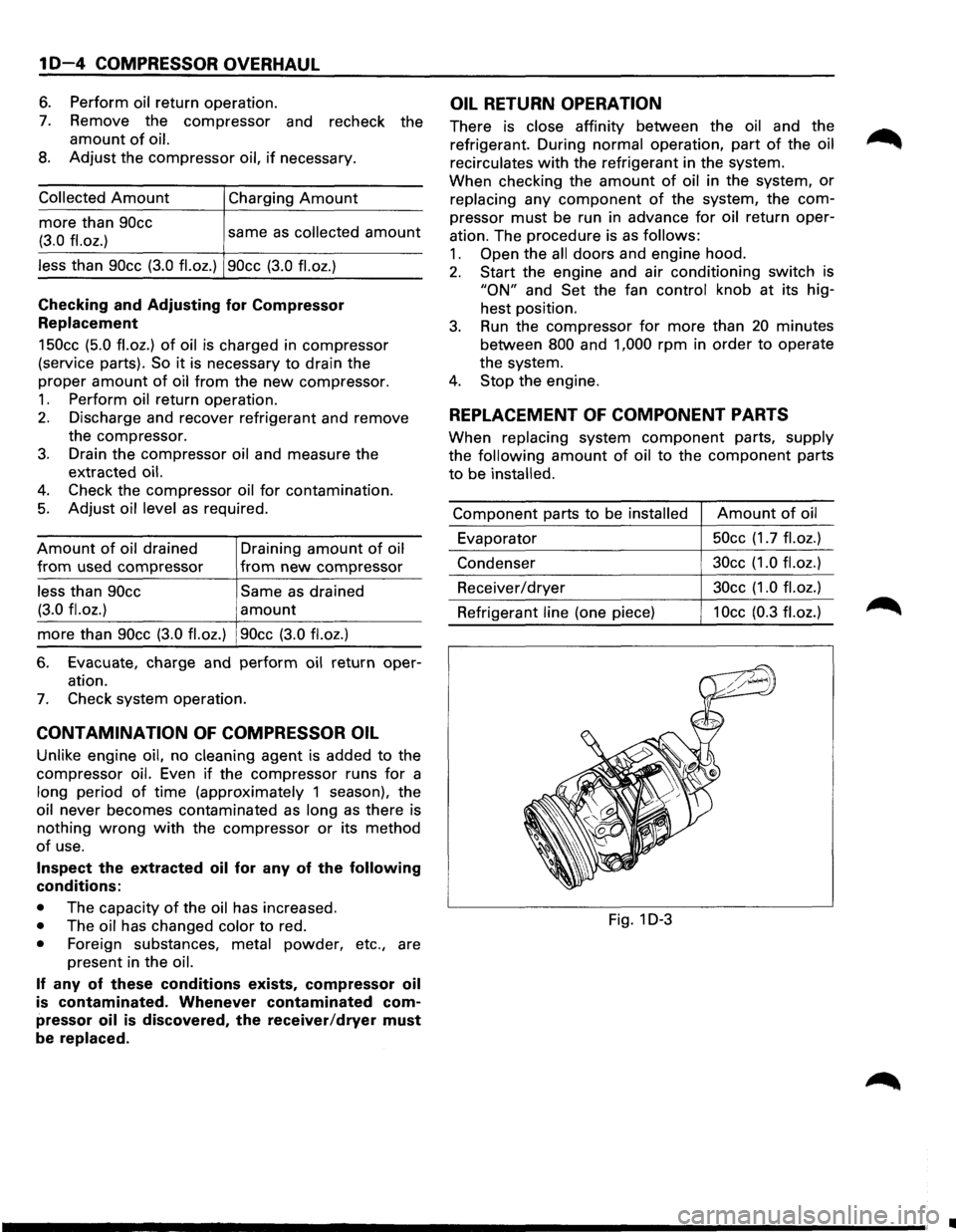
REPLACEMENT OF COMPONENT PARTS
When replacing system component parts, supply
the following
amount of oil to the component parts
to be installed.
Component parts to be installed Amount of oil
Evaporator 50cc
(1.7
fl.oz.)
Condenser 30cc
(1.0 fl.oz.)
Receiver/dryer 30cc
(1.0 fl.oz.)
Refrigerant line (one piece) 1 Occ (0.3 fl. oz.)
Fig. 1 D-3
•
Page 135 of 1928
FRONT END ALIGNMENT 3A-3
ON-VEHICLE SERVICE
INSPECTION
Before making any adjustments affecting caster,
camber or toe-in, the following front end inspection
should be made.
I L•IINSPECT
1. Tires for proper inflation pressure. Refer to
"Wheels and Tires" in section 3E.
2. Front wheel bearings for proper adjustment.
Refer to "Front Wheel Drive" in section 4C.
3. Ball joints, tie rod ends and relay rods. If
excessive looseness is noted, correct before
adjusting. Refer
to "Steering Linkage" in section
3B3.
4. Wheel and tires for run-out. Refer to "Wheels
and Tires" in section 3E.
5. Trim height. If not within specifications, the
correction
must be made before adjusting caster.
6. Steering gear for looseness at the frame.
7. Shock absorbers for leaks or any noticeable
noise.
Refer
to "Front Suspension" in section 3C.
8. Control arms or stabilizer bar attachment for
looseness. Refer to "Front Suspension" in section
3C.
9. Alignment equipment. Follow the manufacturer's
instructions.
10. Level of the vehicle. The vehicle must be on a
level surface.
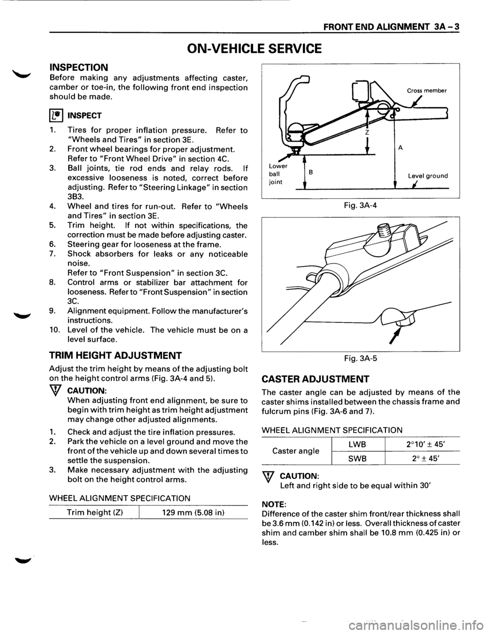
TRIM HEIGHT ADJUSTMENT
Adjust the trim height by means of the adjusting bolt
on the height control arms (Fig. 3A-4 and 5).
W CAUTION:
When adjusting front end alignment, be sure to
begin with trim height as trim height adjustment
may change other adjusted alignments.
1. Check and adjust the tire inflation pressures.
2. Park the vehicle on a level ground and move the
front of the vehicle up and down several times to
settle the suspension.
3. Make necessary adjustment with the adjusting
bolt on the height control arms.
WHEEL
ALIGNMENT SPECIFICATION
Trim height (Z) 129 mm (5.08 in)
Lower
ball joint
B
Fig. 3A-4
Fig. 3A-5
CASTER ADJUSTMENT
Level ground
The caster angle can be adjusted by means of the
caster shims installed between the chassis frame and
fulcrum pins (Fig. 3A-6 and 7).
WHEEL
ALIGNMENT SPECIFICATION
LWB
Caster angle
SWB
W CAUTION:
Left and right side to be equal within 30'
NOTE:
Difference of the caster shim front/rear thickness shall
be 3.6
mm (0.142 in) or less. Overall thickness of caster
shim and camber shim shall be 10.8 mm (0.425 in) or
less.
Page 433 of 1928
4-WHEEL ANTILOCK BRAKE SYSTEM (ABS) 5A4-23
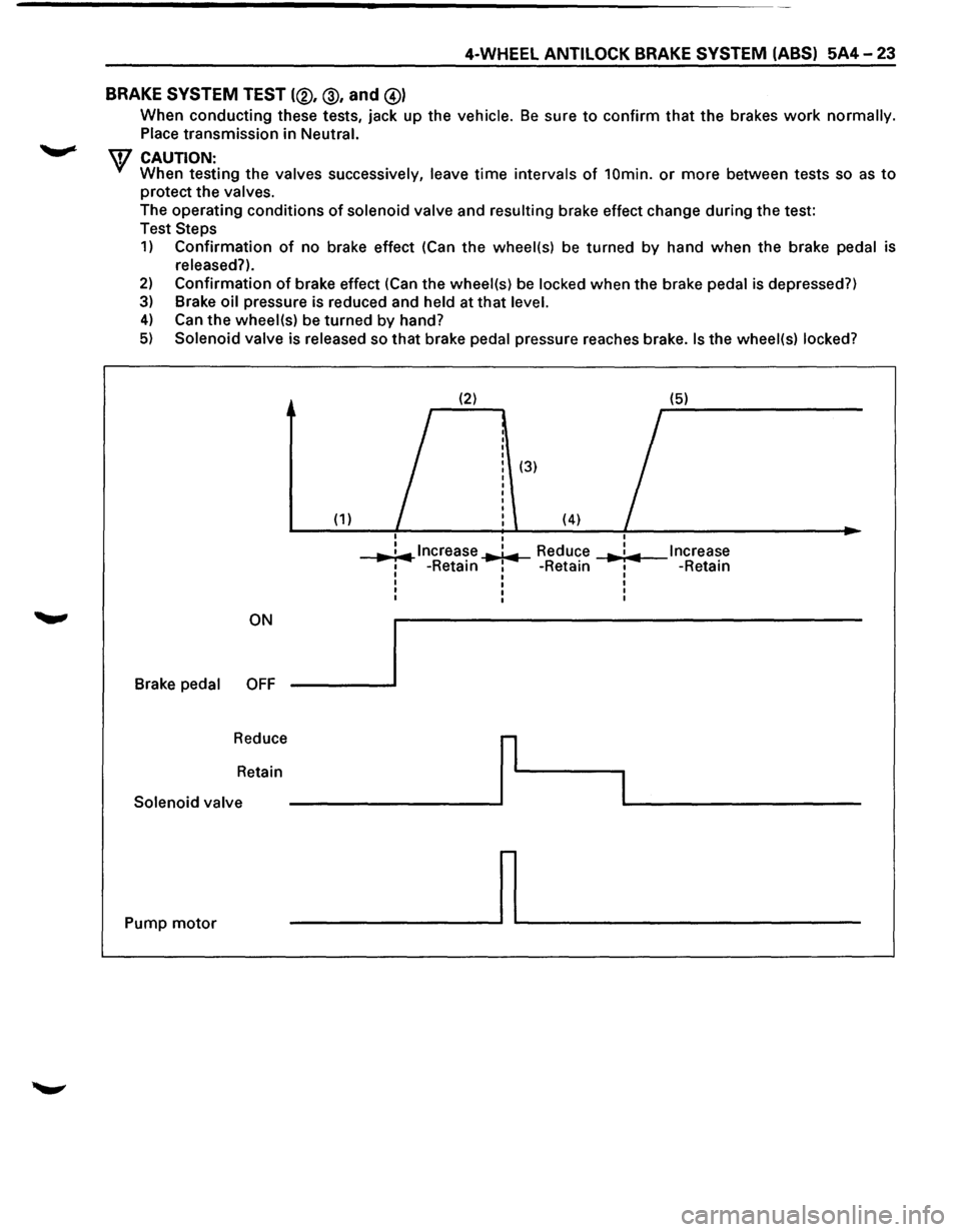
BRAKE
SYSTEM TEST (®, @, and @)
When conducting these tests, jack up the vehicle. Be sure to confirm that the brakes work normally.
Place transmission
in Neutral.
\V CAUTION: When testing the valves successively, leave time intervals of 10min. or more between tests so as to
protect the valves.
The operating conditions
of solenoid valve and resulting brake effect change during the test:
Test
Steps
1) Confirmation of no brake effect (Can the wheel(s) be turned by hand when the brake pedal is
released?).
2) Confirmation of brake effect (Can the wheel(s) be locked when the brake pedal is depressed?)
3) Brake oil pressure is reduced and held at that level.
4) Can the wheel(s) be turned by hand?
5) Solenoid valve is released so that brake pedal pressure reaches brake. Is the wheel(s) locked?
(2) (5)
I
(3)
(1) (4) I
I
..,. ;.,.. lncrea~e ..,.1.,.. Reduce I Increase ... : ... 1 -Retam 1 -Retain I -Retain I I I
I I I
I I I
I I I
ON
Brake
pedal OFF
Reduce
r
Retain
I Solenoid valve
Pump
motor ~
Page 508 of 1928
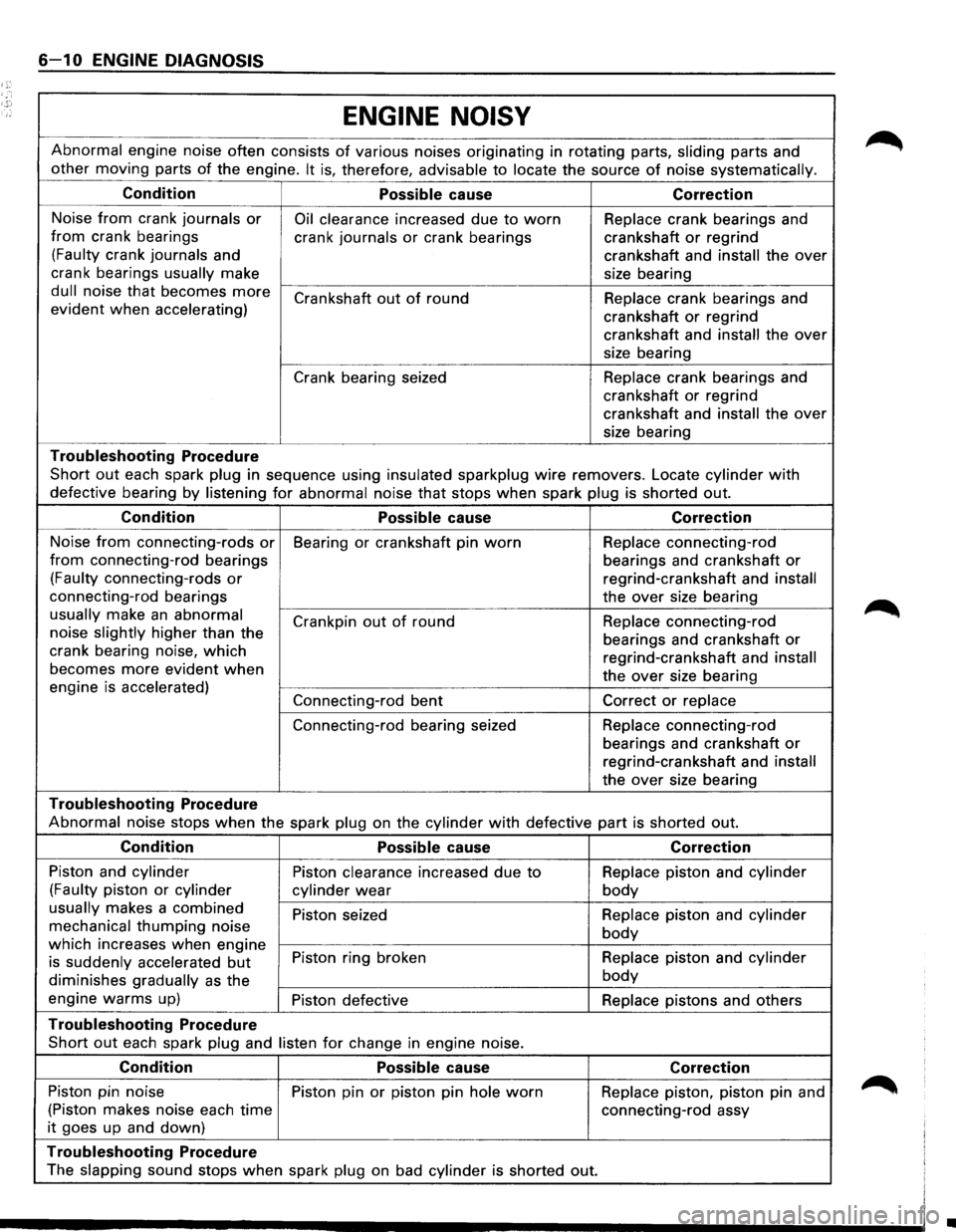
6-10 ENGINE DIAGNOSIS
ENGINE
NOISY
Abnormal engine noise often consists of various noises originating in rotating parts, sliding parts and
other moving parts
of the engine. It is, therefore, advisable to locate the source of noise systematically.
Condition
Possible cause Correction
Noise from crank journals or Oil clearance increased due to worn Replace crank bearings and
from crank bearings
crank journals
or crank bearings crankshaft or regrind
(Faulty crank journals and
crankshaft and
install the over
crank bearings
usually make
size bearing
dull noise that becomes more Crankshaft out of round
Replace crank bearings and
evident when accelerating)
crankshaft
or regrind
crankshaft and
install the over
size bearing
Crank bearing seized Replace crank bearings and
crankshaft or regrind
crankshaft and
install the over
size bearing
Troubleshooting Procedure
Short out each spark plug in sequence using insulated sparkplug wire removers. Locate cylinder with
defective bearing by listening for abnormal noise that stops when spark plug is shorted out.
Condition
Possible cause Correction
Noise from connecting-rods or Bearing or crankshaft pin worn Replace connecting-rod
from connecting-rod bearings
bearings and crankshaft or
(Faulty connecting-rods or regrind-crankshaft and install
connecting-rod bearings
the over size bearing
usually make an abnormal
Crankpin out of round Replace
connecting-rod
noise slightly higher than the
bearings and crankshaft
or crank bearing noise, which regrind-crankshaft and install becomes more evident when the over size bearing
engine is accelerated)
Connecting-rod bent
Correct or replace
Connecting-rod bearing seized Replace
connecting-rod
bearings and crankshaft
or
regrind-crankshaft and install
the over size bearing
Troubleshooting Procedure
Abnormal noise stops when the spark plug on the cylinder with defective part is shorted out.
Condition
Possible cause Correction
Piston and cylinder Piston clearance increased due to Replace piston and cylinder
(Faulty piston or cylinder
cylinder
wear body
usually makes a combined Piston seized Replace piston and cylinder
mechanical thumping noise body which increases when engine Piston ring broken Replace piston and cylinder
is suddenly accelerated but
diminishes gradually as the body
engine warms up) Piston defective Replace pistons and others
Troubleshooting Procedure
Short out each spark plug and listen for change in engine noise.
Condition
Possible cause Correction
Piston pin noise Piston pin or piston pin hole worn Replace piston, piston pin and
(Piston makes noise each time connecting-rod assy
it goes up and down)
Troubleshooting Procedure
The slapping sound stops when spark plug on bad cylinder is shorted out.
•
Page 644 of 1928
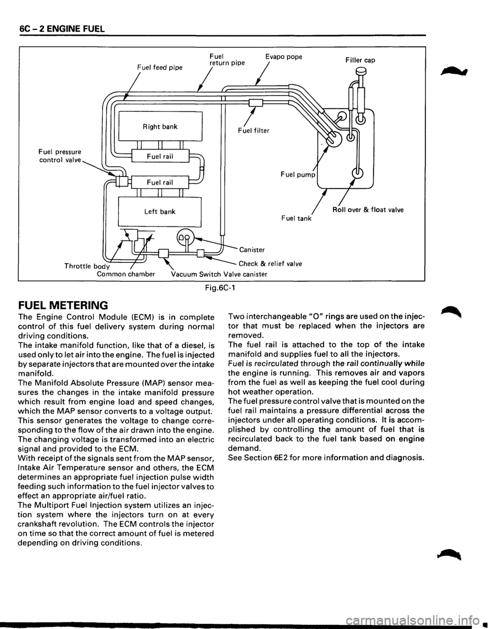
6C - 2 ENGINE FUEL
Fuel
Fuel
feed pipe return pipe Evapo pope
Fuel pressure
control valve Right
bank
Left bank Fuel tank
Canister
Throttle body Common chamber
Check & relief
valve
Vacuum Switch Valve canister
Fig.6C-1
FUEL METERING
The Engine Control Module (ECM) 1s 1n complete
control of this fuel delivery system during normal
driving conditions.
The intake manifold function, like that of a diesel, is
used
only to let air into the engine. The fuel is injected
by separate injectors that are mounted over the intake
manifold.
The Manifold Absolute Pressure (MAP) sensor mea
sures
the changes in the intake manifold pressure
which result from engine load and speed changes,
which the MAP sensor converts to a voltage output.
This sensor generates the voltage to change corre
sponding to the flow ofthe air drawn into the engine.
The
changing voltage is transformed into an electric
signal and provided to the ECM.
With receipt of the signals sent from the MAP sensor,
Intake Air Temperature sensor and others, the ECM
determines an appropriate fuel injection pulse width
feeding such information to the fuel injector valves to
effect an appropriate air/fuel ratio.
The
Multipart Fuel Injection system utilizes an injec
tion system where the injectors turn on at every
crankshaft revolution. The ECM controls the injector
on time so that the correct amount of fuel is metered
depending on driving conditions.
Two interchangeable "0" rings are used on the injec
tor that must be replaced when the injectors are
removed.
The fuel rail is attached to the top of the intake
manifold and supplies fuel to all the injectors.
Fuel is recirculated
through the rail continually while
the engine is running. This removes air and vapors
from the fuel as well as keeping the fuel cool during
hot weather operation.
The fuel pressure control valve that is mounted on the
fuel rail maintains a pressure differential across the
injectors under all operating conditions. It is accom
plished by controlling the amount of fuel that is
recirculated back
to the fuel tank based on engine
demand.
See Section 6E2 for more information and diagnosis.
;au
•