fuse ISUZU TROOPER 1995 Owner's Guide
[x] Cancel search | Manufacturer: ISUZU, Model Year: 1995, Model line: TROOPER, Model: ISUZU TROOPER 1995Pages: 1928
Page 723 of 1928
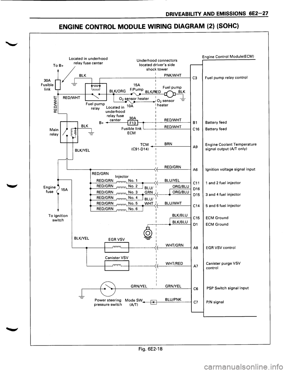
DRIVEABILITY AND EMISSIONS 6E2-27
ENGINE CONTROL MODULE WIRING DIAGRAM (2) (SOHC)
Located in underhood Engine Control
Module(ECM) Underhood connectors
To B+ relay fuse center located driver's side
/r BLK r----------s-ho-c-1-:-t-ow_:_::...:~.:..:K!Wc..:...:..:H:...:T.:..__---I C3 Fuel pump relay control
30A
Fusible
link
15A I F/P 1 Fuel pump BLK/ORG ~~
02 sensor heater 1 1 0 -2 sensor -10A 1 heater Fuel pump
BLK/YEL
relay Located in underhood relay fuse
center
B+ ------1
I
REO/WHT t---.-----t--:..:.::::..=.!...:...:..:..:...:_.:..._--1 B 1 Battery feed
REO/WHT
'-----t--..:.:..::-=:!....:c.:.:...:.-=-------1 C16 Battery feed
TCM BRN (C91-014) -_.:..._--=..:..:..:...:----1 A9 Engine Coolant Temperature signal output (A/T only)
L----~-----------~~-.:..:R.:::EO~/~G~R~N_:_--IA6 Ignition
voltage signal input
Engine
fuse 15A
To
ignition switch BLK/YEL
=
REO/GRN
REO/GRN
REO/GRN
REO/GRN
REO/GRN
REO/GRN
REO/GRN
ORG/BLU 016
ORG/BLU 015
L:...:..::..:-=---.....-:..:.:....:...!._{ L_B::..:L:..:U:c..IW:..:..:...:.HT_:__--l c " 14
BLK/BLU C15
,--.----<.._.:::B.:::LKI=B.::.LU=---1 01
GRN/YEL GRN/YEL
~--~~~~--~~~~--~C6
Power steering Mode SW--+*-f--=-8=-LU~/.:..P.:..:N~K:___---l pressure switch (A/T) C7
Fig. 6E2-18
1 and 2 fuel injector
3 and 4 fuel injector
5 and 6 fuel injector
ECM Ground
ECM Ground
EGR VSV control
Canister purge VSV
control
PSP Switch signal input
P/N signal
Page 724 of 1928
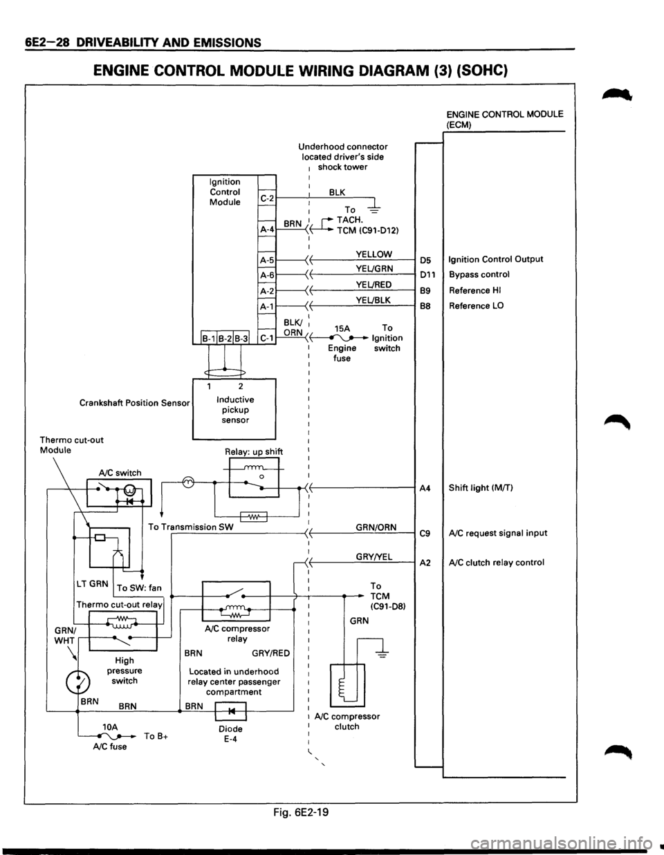
6E2-28 DRIVEABILITV AND EMISSIONS
ENGINE CONTROL MODULE WIRING DIAGRAM (3) (SOHC)
Ignition Control
Module Underhood
connector
located driver's side
1 shock tower I I 1:-2~--~~--~B~L~K~--~
- : To -4-
-BRN 1. r--TACH.
A-4 ~ TCM IC91-D12) -I
I
YELLOW
·~ YEL!GRN \ VEL/RED YEL!BLK
I--B-1IB-2IB-3l C-1
l
1 2
Crankshaft Position Sensor Inductive pickup
sensor I
I
I
I
Thermo cut-out I
I
I
I
I
n I
Mo\\I•Silj ~~
To Transmission SW ~ r-------------------~ -
'---<
LT GRN To SW: fan
Thermo cut-out relay'
GRN/
WHT
....--+-----~
BRN
High
pressure switch
BRN
NC compressor relay
BRN GRY/RED
Located in underhood relay center passenger
compartment
BRN r::-1
I
I
r
I
I
I
I
I
I
I
I
I
I
I
I
I
I
GRN/ORN
GRY!YEL To
TCM IC91-D8)
GRN
n
l
I I 1 NC compressor 10A ~ToB+ NCfuse
Diode E-4
I clutch I
I
' ' '
Fig. 6E2-19
A4
C9
A2
~
ENGINE CONTROL MODULE (ECM)
Reference HI
Reference LO
Shift light (MfT)
NC request signal input
NC clutch relay control
..
Page 725 of 1928
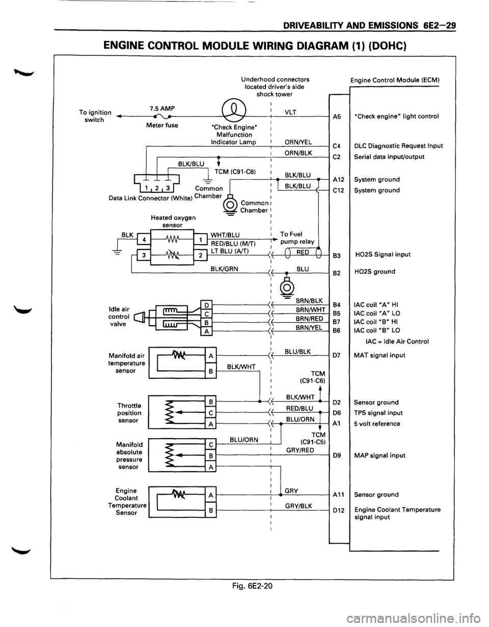
DRIVEABILITY AND EMISSIONS 6E2-29
ENGINE CONTROL MODULE WIRING DIAGRAM (1) (DOHC)
Underhood connectors
located driver's side
shock
tower
To ignition
switch 7.5AMP ,.... ~ ®
I
I
Meter fuse I "Check Engine" I Malfunction I Indicator Lamp I
I
'
I 8LK/8LU I
D
I l TCM (C91-C8) 1
~ 1 2 ~ ~ co.;;mo~~ : ata Link Connector (White) Chamber 1 0 Common1 Chamber 1 Heated oxygen -= I
rg
=F
leair s ontrol C] alve
ld c v
M
te anifold
air
mperature sensor
Throttle position sensor
Manifold absolute pressure sensor
Engine
Coolant
T emperature
Sensor
sensor I
I
-A/IN-1:'1 WHT/8LU I
~ RED/8LU (M/TI I
~ ""21 L T 8LU (A/TI II ....::....1 ,1,
8LK/GRN :,
I
I
I
I
cam l:
I
I
Au A )I y"-\1 r--
8 8LK/WHT I I
I
I
I
8 ~ 1--II
~ r£ \ 'I A ,1,
8LU/ORN I
r£ ~ I
8 ~ f--I A I
I
I
_A& a A I y"-I r--I 8 I
I
I
Fig. 6E2-20
VLT
ORNNEL
ORN/8LK
8LK/8LU
I 8LK/8LU
To Fuel
pump relay
( ) RED ( v v
8LU
~ -8RN/8LK
8RN/WHT
8RN/RED
8RNNEL
8LU/8LK
TCM (C91-C6)
8LK/WHT !
RED/8LU
8LU/ORN
TCtM
(C91-C5)
GRY/RED
GRY
GRY/8LK Engine
Control
Module (ECMI
.-----
AS "Check engine" light control
C4 DLC Diagnostic Request lnpu
C2 Serial data input/output
A12 System ground
C12 System ground
83
H02S Signal input
82 H02S ground
84
lAC coil "A" HI
85 lAC coil "A" LO
87 lAC coil "8" HI
86 lAC coil "8" LO
lAC = Idle Air Control
D7 MAT signal input
D2 Sensor ground
D6 TPS signal input
A1 5 volt reference
D9 MAP signal input
A11 Sensor ground
D12 Engine Coolant Temperatur e signal input
......__
Page 726 of 1928
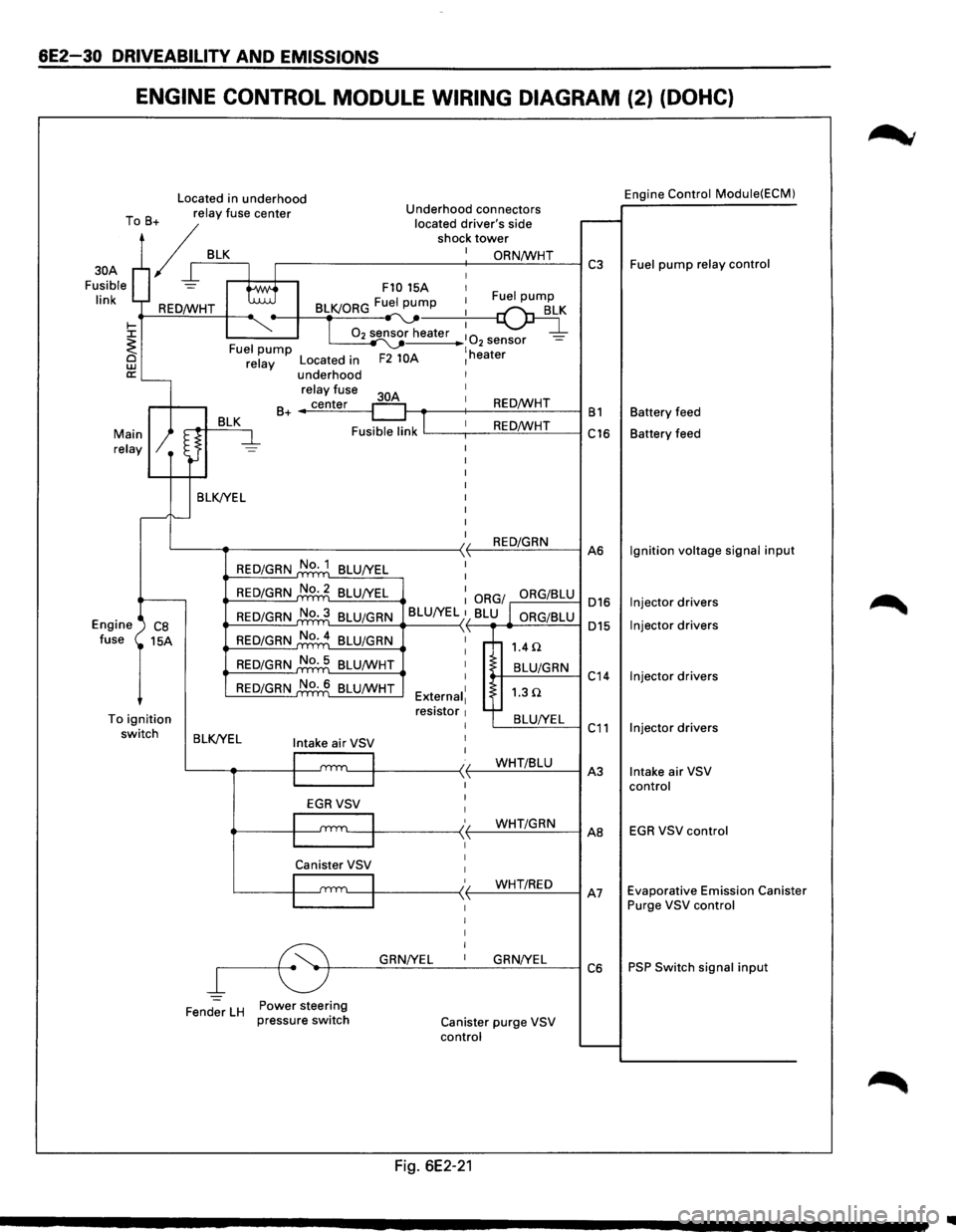
6E2-30 DRIVEABILITY AND EMISSIONS
ENGINE CONTROL MODULE WIRING DIAGRAM (2) (DOHC)
Located in underhood Engine Control Module(ECM)
T B relay
fuse center Underhood connectors
o + located
driver's side r--. / shock tower
/ I BLK.---+-I_: ~==-----------+-: __ O_R_N...:./W_H_T_--1 C3 Fuel pump relay control
Fusible
= tti F10 15A 1
30A
I' k I 1 Fuel pump In REO/WHT BLK/ORG Fu:.._pu~
~ ~-T 02 sensor heater :
0 _ ~ I ~ 2 sensor -<. Fuel pump ~ lh @ relay Located in F2 10A 1 eater
a:'---underhood
relay fuse I
BLK 30A
1 B+ _..;c:..::ec:..:n-=.:te:.:..r_-1 REO/WHT B1 Battery
feed
Fusible link
lL---,--1 _ _:.:R:.=E-==O'-'fW:..:..:....:H-=-T---i C16 Battery feed Main relay
BLK/YEL I
I
I
I
I
I
I
L---~--------------<)1 REO/GRN ,1, A6
Engine ') CB fuse 15A
To ignition switch
REO/GRN No. 1
BLU/YEL I
REO/GRN No.2 BLU/YEL : ORG/ ORG/BLU 016
015
REO/GRN No.3 BLU/GRN
BLU/YEL }1 BLU l ORG/BLU L....::-=-=.:...=.:._.._ __ -<
REO/GRN No.4
BLU/GRN \'
REO/GRN No. 5
BLU/WHT
REO/GRN No. 6 BLU/WHT I
I
External1 resistor 1 I
1.4 n
t-+--B_L-'U/_G_R_N--1 C
14
1.3Q
'---=B:..::L:..::U_:_IY;_:E:.:L~ C 11 BLK/YEL Intake air VSV I
I
l
I I t.__-1~-----< t--...:...W:..:.H.:....:.T.:...::/B:..::Lc::.U_-1 A
3
I
I
I
EGRVSV
'---111 ____ -<' (-_...:...W.:....:.H.:....:.T.:...c/G=-R_N_-1 AB
Canister VSV 1
I 1
/ WHT/REO I '---1~-----<,f--,--"------1 A7 ~------~ I I I I
~r---G~RN~/Y~E_L __ 1 __ G~R_N...:.!Y_EL_~ C 6
Fender
LH Power steering
pressure switch Canister purge VSV
control
Fig. 6E2-21
Ignition voltage signal input
Injector drivers
Injector drivers
Injector drivers
Injector drivers
Intake air VSV
control
EGR VSV control
Evaporative Emission Canister
Purge VSV control
PSP Switch signal input
1111
Page 727 of 1928
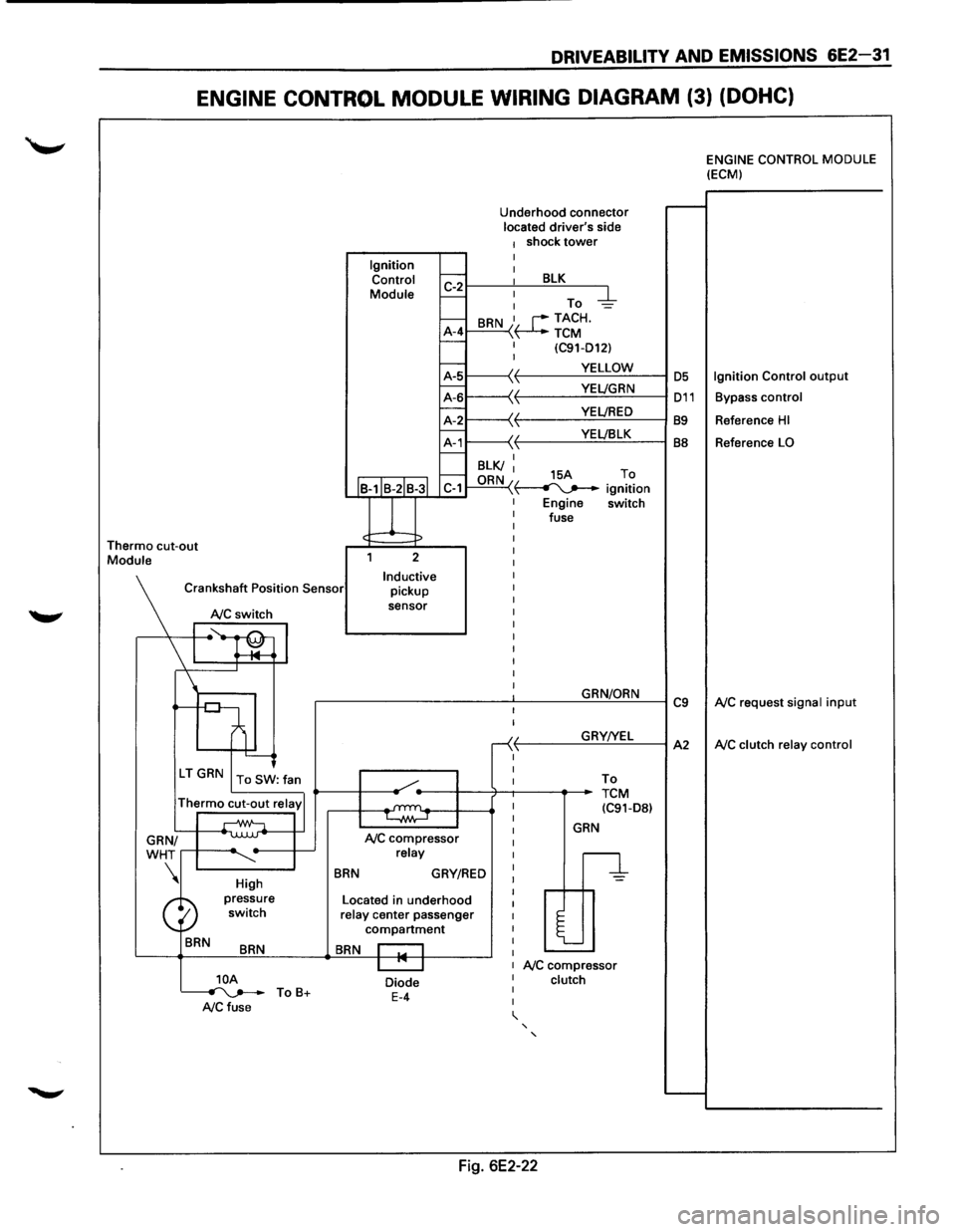
DRIVEABILITV AND EMISSIONS 6E2-31
ENGINE CONTROL MODULE WIRING DIAGRAM (3) (DOHC)
Thermo cut-out Module Ignition
Control
Module
J
Underhood connector located driver's side 1 shock tower I
~r---~: ___ B~L=K~--~
I-: To -d::-1--A-4 I-
BRN I, r--TACH. \~TCM I (C91-D12) I
~1-----\(. f-------...:.Y.=.E:::LL:.:O:..:W:..:._--1 OS
~L-----'~
11---\-{' t----Y:..::E~LJ:..:::B.:::LK~--l BB f.---I BLK/ I f.---ORN 15A To C-1 "\~ ignition
Engine switch
fuse
2
Inductive pickup
sensor
Crankshaft
Position Sensor
NC switch
I ~~ l '--------J
\'r-----.
High
BRN
BRN
]_OA ~ ToB+ A/C fuse
BRN
NC compressor relay
GRY/RED
Located in underhood relay center passenger compartment
BRN I I I "' I
Diode E-4
I
I
-<( ,1,
I
I
GRN/ORN
GRY!YEL
To
TCM (C91-D8l
GRN
n
l
NC compressor clutch
' '
Fig. 6E2-22
C9
A2
ENGINE CONTROL MODULE (ECM)
Ignition Control output
Bypass control
Reference HI
Reference LO
NC request signal input
NC clutch relay control
Page 734 of 1928
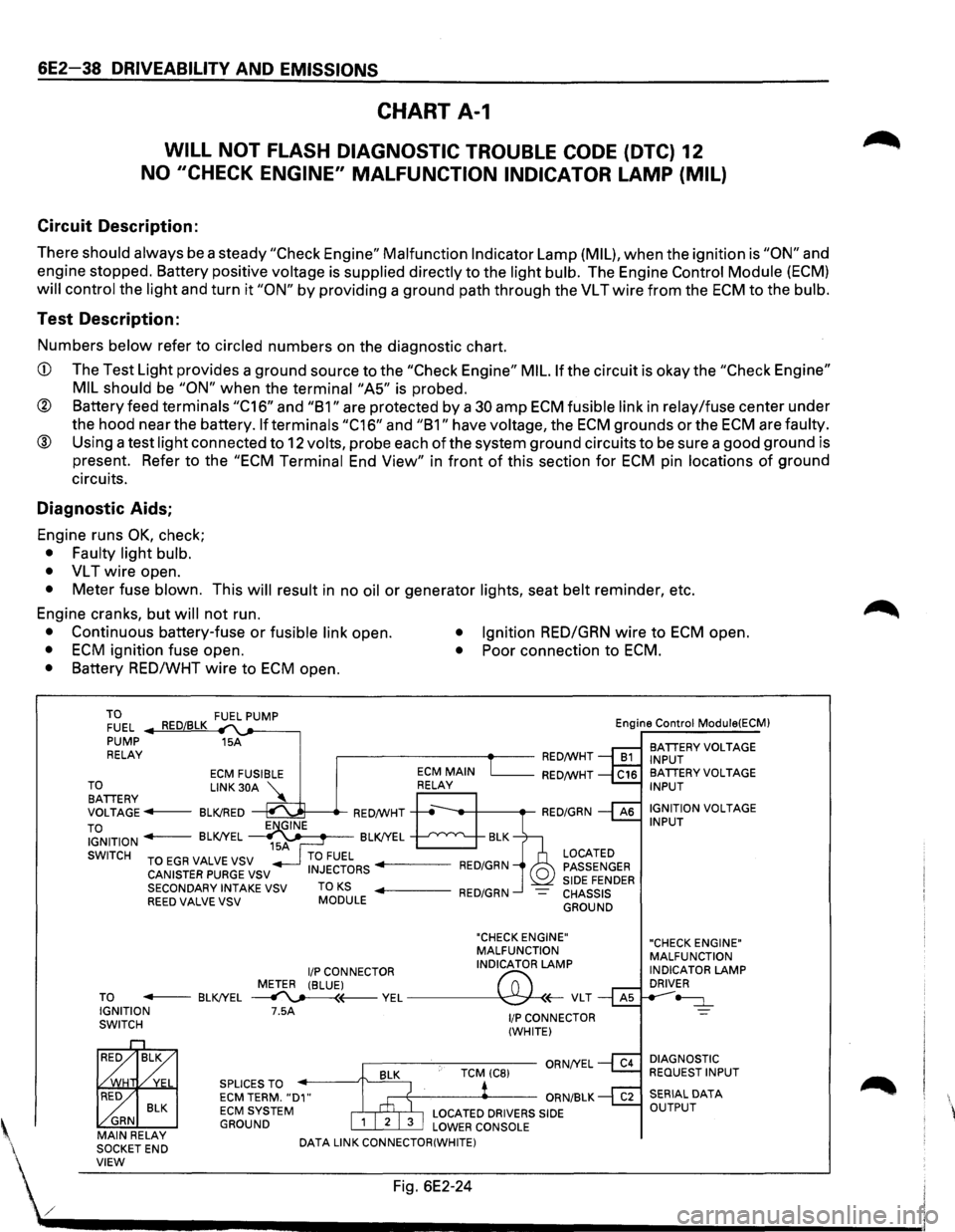
6E2-38 DRIVEABILITV AND EMISSIONS
CHART A-1
WILL NOT FLASH DIAGNOSTIC TROUBLE CODE (DTC) 12
NO "CHECK ENGINE" MALFUNCTION INDICATOR LAMP (MIL)
Circuit Description:
There should always be a steady "Check Engine" Malfunction Indicator Lamp (MIL), when the ignition is "ON" and
engine stopped. Battery positive
voltage is supplied directly to the light bulb. The Engine Control Module (ECM)
will control the light and turn it "ON" by providing a ground path through the VL T wire from the ECM to the bulb.
Test Description:
Numbers below refer to circled numbers on the diagnostic chart.
CD The Test Light provides a ground source to the "Check Engine" MIL. If the circuit is okay the "Check Engine"
MIL should
be "ON" when the terminai"A5" is probed.
® Battery feed terminals "C16" and "B1" are protected by a 30 amp ECM fusible link in relay/fuse center under
the hood near the battery.
If terminals "C16" and "B1" have voltage, the ECM grounds or the ECM are faulty.
® Using a test light connected to 12 volts, probe each of the system ground circuits to be sure a good ground is
present. Refer to the
"ECM Terminal End View" in front of this section for ECM pin locations of ground
circuits.
Diagnostic Aids;
Engine runs OK, check;
• Faulty light bulb.
•
VL T wire open.
• Meter fuse blown. This will result in no oil or generator lights, seat belt reminder, etc.
Engine cranks, but
will not run.
• Continuous battery-fuse or fusible link open. • Ignition RED/GRN wire to ECM open.
• ECM ignition fuse open. • Poor connection to ECM.
• Battery RED/WHT wire to ECM open.
TO FUEL .._..,==~ ,__,__-----, PUMP 15A
RELAY .--------~~-RED/WHT Engine
Control
Module(ECM)
BATIERY VOLTAGE
INPUT
ECM FUSIBLE RED/WHT TO LINK 30A '\.. BATIERY ~ VOLTAGE---BLK!RED ~---.-RED/WHT
TO IGNITION - BLK!YEL ~~~-BLK!YEL --'--'~"'---..__
SWITCH TO EGR VALVE VSV
CANISTER PURGE VSV
SECONDARY INTAKE VSV
REED VALVE VSV TO KS MODULE
LOCATED
PASSENGER
SIDE FENDER CHASSIS GROUND
"CHECK ENGINE"
MALFUNCTION
I/P CONNECTOR INDICATOR LAMP
METER (BLUE)
("";:; TO - BLK!YEL ~(---VEL~(;-VLT IGNITION 7.5A SWITCH
BLK ~ GRN MAIN RELAY
SOCKETEND SPLICES
TO ECM TERM. "D1" ECM SYSTEM GROUND
DATA
LINK CONNECTOR(WHITE)
1/P CONNECTOR
(WHITE)
BA TIERY VOLTAGE INPUT
IGNITION
VOLTAGE INPUT
"CHECK ENGINE"
MALFUNCTION
INDICATOR
LAMP DRIVER
~
DIAGNOSTIC REQUEST INPUT
' VIEW Fig. 6E2-24
./ .................................... __________________________ _
Page 735 of 1928
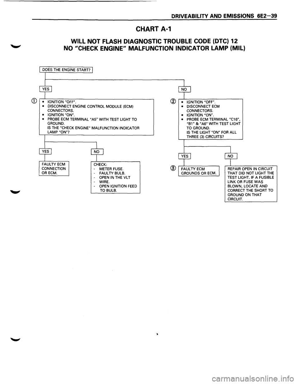
DRIVEABILITV AND EMISSIONS 6E2-39
CHART A-1
WILL NOT FLASH DIAGNOSTIC TROUBLE CODE (DTC) 12
NO 11CHECK ENGINE" MALFUNCTION INDICATOR LAMP (MIL)
CD • IGNITION "OFF".
• DISCONNECT ENGINE CONTROL MODULE (ECM) CONNECTORS.
• IGNITION "ON". • PROBE ECM TERMINAL "A5" WITH TEST LIGHT TO GROUND. IS THE "CHECK ENGINE" MALFUNCTION INDICATOR LAMP "ON"?
FAULTY ECM CONNECTION OR ECM. CHECK:
- METER FUSE. FAUL TV BULB. OPEN IN THE VL T
-WIRE. -OPEN IGNITION FEED TO BULB.
@ • IGNITION "OFF".
®
• DISCONNECT ECM CONNECTORS.
• IGNITION "ON".
• PROBE
ECM TERMINAL "C16", "B1" & "A6" WITH TEST LIGHT
TO GROUND. IS THE LIGHT "ON" FOR ALL THREE (3) CIRCUITS?
REPAIR OPEN IN CIRCUIT
THAT DID NOT LIGHT THE TEST LIGHT. IF A FUSIBLE
LINK OR FUSE WAS BLOWN, LOCATE AND CORRECT THE SHORT TO
GROUND ON THAT CIRCUIT.
Page 744 of 1928
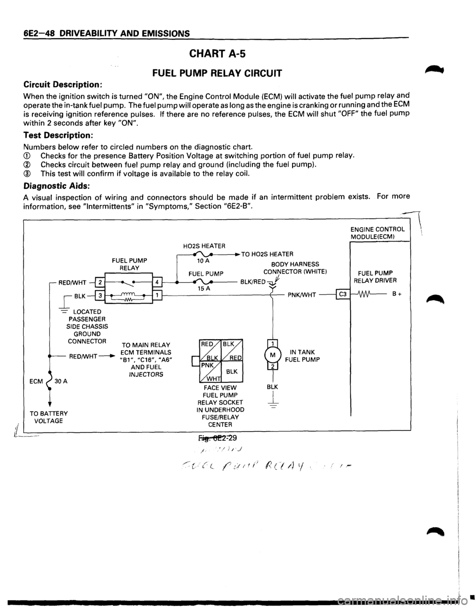
6E2-48 DRIVEABILITY AND EMISSIONS
CHART A-5
FUEL PUMP RELAY CIRCUIT
Circuit Description:
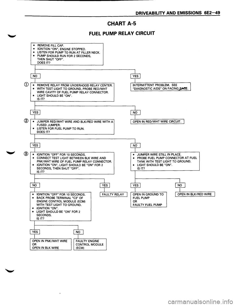
When the ignition switch is turned "ON", the Engine Control Module (ECM) will activate the ft:Jel pump relay and
operate the in-tank
fuel pump. The fuel pump will operate as long as the engine is cranking or running and the ECM
is receiving ignition reference pulses. If there are no reference pulses, the ECM will shut "OFF" the fuel pump
within 2 seconds after key
"ON".
Test Description:
Numbers below refer to circled numbers on the diagnostic chart.
CD Checks for the presence Battery Position Voltage at switching portion of fuel pump relay.
® Checks circuit between fuel pump relay and ground (including the fuel pump).
® This test will confirm if voltage is available to the relay coil.
Diagnostic Aids:
A visual inspection of wiring and connectors should be made if an intermittent problem exists. For more
information, see
"lntermittents" in "Symptoms," Section "6E2-B".
ECM
FUEL PUMP
RELAY
H02S HEATER _. ___ .,.TO H02S HEATER
10 A BODY HARNESS CONNECTOR (WHITE)
RED/WHT 1---_.__.., '"..._.. __ BLK!RED...J
_[BLK
-= LOCATED PASSENGER SIDE CHASSIS
GROUND
CONNECTOR
TO MAIN RELAY
RED/WHT---+-ECM TERMINALS "81", "C16", 11A6" AND FUEL INJECTORS
FACE VIEW FUEL PUMP RELAY SOCKET
BLK
j__
IN TANK FUEL PUMP
TO BATIERY IN UNDERHOOD ENGINE
CONTRO:-- MODULE(ECM) ·.
FUEL PUMP RELAY DRIVER
8+
VOLTAGE
FUSE/RELAY
i L---------------------------C-EN_T_E_R _______________________ ~
lL---f~. 6E2=29
/
'"·:c·t( (7.::!11t.~ l<(/1) 1/. i-
•
Page 745 of 1928
DRIVEABILITV AND EMISSIONS 6E2-49
CHART A-5
FUEL PUMP RELAY CIRCUIT
• REMOVE FILL CAP. • IGNITION "ON", ENGINE STOPPED.
• LISTEN FOR PUMP TO RUN AT FILLER NECK. • PUMP SHOULD RUN FOR 2 SECONDS, THEN SHUT "OFF". DOES IT?
I
CD
$ $
• REMOVE RELAY FROM UNDERHOOD RELAY CENTER. INTERMITTENT PROBLEM. SEE I • WITH TEST LIGHT TO GROUND, PROBE RED/WHT "DIAGNOSTIC AIDS" ON FACING~. WIRE CAVITY OF FUEL PUMP RELAY CONNECTOR.
• LIGHT SHOULD BE "ON". IS IT?
I
$
$
• JUMPER RED/WHT WIRE AND BLK/RED WIRE WITH A OPEN IN RED/WHT WIRE CIRCUIT. I FUSED JUMPER. • LISTEN FOR FUEL PUMP TO RUN. DOES IT?
I
$ $
• IGNITION "OFF" FOR 10 SECONDS. • JUMPER WIRE STILL IN PLACE. ® • CONNECT TEST LIGHT BETWEEN BLK WIRE AND • PROBE FUEL PUMP CONNECTOR AT FUEL
PNK/WHT WIRE OF FUEL PUMP RELAY CONNECTOR. TANK WITH TEST LIGHT TO GROUND. • IGNITION "ON", LIGHT SHOULD BE "ON" FOR 2 • LIGHT SHOULD BE "ON". SECONDS, THEN SHUT "OFF". IS IT? IS IT?
I
$
$ ~ $
• IGNITION "OFF" FOR 10 SECONDS. I FAULTY RELAY I OPEN IN GROUND TO I OPEN IN BLK/RED WIRE I • BACK PROBE TERMINAL "C3" OF FUEL PUMP ENGINE CONTROL MODULE (ECM) OR WITH TEST LIGHT TO GROUND. FAULTY FUEL PUMP • IGNITION "ON". • LIGHT SHOULD BE "ON" FOR 2 SECONDS.
IS IT?
I
$ $
OPEN IN PNK/WHT WIRE FAULTY ENGINE OR CONTROL MODULE
OPEN IN BLK WIRE (ECM)
Page 746 of 1928
6E2-50 DRIVEABILITY AND EMISSIONS
Circuit Description:
CHART A-7
FUEL SYSTEM PRESSURE TEST
(Page 1 of 3)
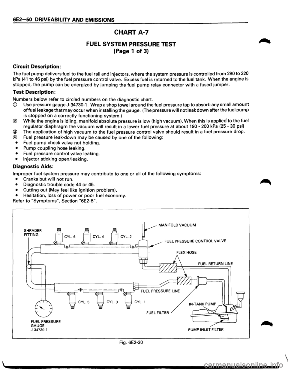
The fuel pump delivers fuel to the fuel rail and injectors, where the system pressure is controlled from 280 to 320
kPa (41 to 46 psi) by the fuel pressure control valve. Excess fuel is returned to the fuel tank. When the engine is
stopped, the
pump can be energized by jumping the fuel pump relay connector with a fused jumper.
Test Description:
Numbers below refer to circled numbers on the diagnostic chart.
CD Use pressure gauge J-34730-1. Wrap a shop towel around the fuel pressure tap to absorb any small amount
offuelleakage that may occur when installing the gauge. (The pressure will not leak down after the fuel pump
is stopped on a correctly functioning system.)
® While the engine is idling, manifold absolute pressure is low (high vacuum). When this is applied to the fuel
regulator
diaphragm the vacuum will result in a lower fuel pressure at about 190-200 kPa (25-30 psi)
@ The application of high vacuum to the fuel pressure control valve should result in a fuel pressure drop.
@ Fuel pressure leak-down may be caused by one of the following:
• Fuel
pump check valve not holding.
•
Pump coupling hose leaking.
• Fuel
pressure control valve leaking.
• Injector
sticking open/leaking.
Diagnostic Aids:
Improper fuel system pressure may contribute to one or all of the following symptoms:
• Cranks but will not run.
• Diagnostic trouble code 44 or 45.
• Cutting out (May feel like ignition problem).
•
Hesitation, loss of power or poor fuel economy.
Refer
to "Symptoms", Section "6E2-B".
SHRADER FITTING
FUEL PRESSURE
GAUGE
J-34730-1
Fig. 6E2-30
MANIFOLD VACUUM
FUEL PRESSURE CONTROL VALVE
FUEL RETURN LINE
FUEL FILTER
PUMP INLET FILTER