fuse ISUZU TROOPER 1995 Repair Manual
[x] Cancel search | Manufacturer: ISUZU, Model Year: 1995, Model line: TROOPER, Model: ISUZU TROOPER 1995Pages: 1928
Page 832 of 1928
6E2-136 DRIVEABILITY AND EMISSIONS
CHART C-3
EVAPORATIVE EMISSION CANISTER PURGE VALVE CHECK
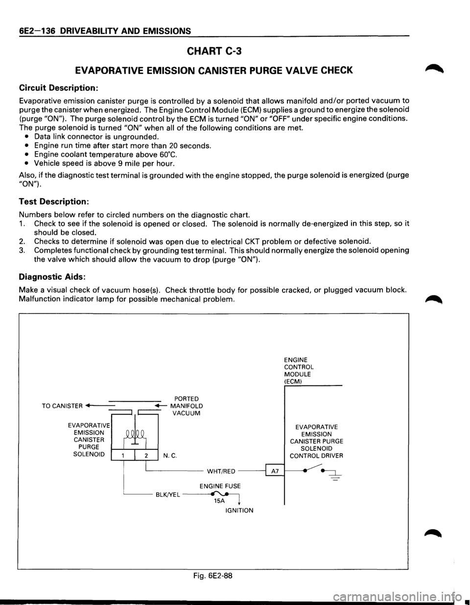
Circuit Description:
Evaporative emission canister purge is controlled by a solenoid that allows manifold and/or ported vacuum to
purge the canister when energized. The Engine Control Module (ECM) supplies a ground to energize the solenoid
(purge "ON"). The purge solenoid control by the ECM is turned "ON" or "OFF" under specific engine conditions.
The purge
solenoid is turned "ON" when all of the following conditions are met.
• Data link connector is ungrounded.
• Engine run time after start more than 20 seconds.
• Engine coolant temperature above 60°C.
• Vehicle speed is above 9 mile per hour.
Also, if the diagnostic test terminal is grounded with the engine stopped, the purge solenoid is energized (purge
"ON").
Test Description:
Numbers below refer to circled numbers on the diagnostic chart.
1. Check to see if the solenoid is opened or closed. The solenoid is normally de-energized in this step, so it
should be closed.
2. Checks to determine if solenoid was open due to electrical CKT problem or defective solenoid.
3. Completes functional check by grounding test terminal. This should normally energize the solenoid opening
the
valve which should allow the vacuum to drop (purge "ON").
Diagnostic Aids:
Make a visual check of vacuum hose(s). Check throttle body for possible cracked, or plugged vacuum block.
Malfunction
indicator lamp for possible mechanical problem.
EVAPORATIVE
EMISSION CANISTER
PURGE SOLENOID N.C.
L__ _____ WHT/RED -----;
ENGINE FUSE
BLKJYEL~ 15A ~
IGNITION
Fig. 6E2-88
ENGINE
CONTROL
MODULE (ECM)
EVAPORATIVE EMISSION
CANISTER
PURGE SOLENOID
CONTROL DRIVER
•
Page 838 of 1928
6E2-142 DRIVEABILITY AND EMISSIONS
CHART C-40-1
ELECTRONIC IGNITION (EI) MISFIRE AT IDLE
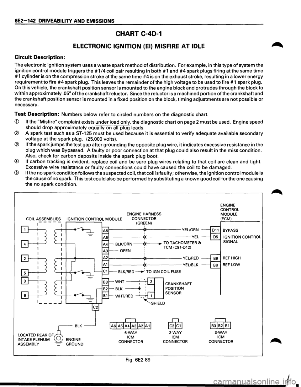
Circuit Description:
The electronic ignition system uses a waste spark method of distribution. For example, in this type of system the
ignition
control module triggers the #1 /4 coil pair resulting in both #1 and #4 spark plugs firing at the same time
# 1
cylinder is on the compression stroke at the same time #4 is on the exhaust stroke, resulting in a lower energy
requirement
to fire #4 spark plug. This leaves the remainder of the high voltage to be used to fire # 1 spark plug.
On this vehicle, the crankshaft position sensor is mounted to the engine block and protrudes through the block to
within approximately .05" ofthe crankshaft reluctor. Since the reluctor is a machined portion ofthe crankshaft and
the crankshaft position sensor is mounted in a fixed position on the
block, timing adjustments are not possible or
necessary.
Test Description: Numbers below refer to circled numbers on the diagnostic chart.
CD If the "Misfire" complaint exists under load only, the diagnostic chart on page 2 must be used. Engine speed
should drop approximately equally on all plug leads.
® A spark test such as a ST-125 must be used because it is essential to verify adequate available secondary
voltage at the spark plug. (25,000 volts).
@ If the spark jumps the test gap after grounding the opposite plug wire, it indicates excessive resistance in the
plug which was Bypassed. A faulty or poor connection at that plug could also result in the miss condition.
Also, check for carbon deposits inside the spark plug boot.
@ If carbon tracking is evident, replace coil and be sure plug wires relating to that coil are clean and tight.
Excessive
wire resistance or faulty connections could have caused the coil to be damaged.
@ If the no spark condition follows the suspected coil, that coil is faulty; otherwise, the ignition control module is
the cause
of no spark. This test could also be performed by substituting a known good coil for the one causing
the no spark condition.
ENGINE HARNESS
COIL ASSEMBLIES IGNITION CONTROL MODULE CONNECTOR
1-- - - -(GREEN)
~ '--1-1 -+---,
I
:TI
:D
r---------~~----------YE~GRN
~--------~~-------------VEL ' BLKJORN -----4---+-TO TACHOMETER & •
TCM (C91-D12) OPEN ! ' r---------~~----------YE~RED
r-----------<1~----------YEL!BLK ' BLKJRED ___..,TO IGN COIL FUSE
IAsiAsl;rJIA21A 1!
6-WAY ICM
CONNECTOR
Fig. 6E2-89
CRANKSHAFT
POSITION
SENSOR
lc0§,1
2-WAY ICM
CONNECTOR ENGINE
CONTROL
MODULE
(ECM)
BYPASS IGNITION CONTROL
SIGNAL
REF HIGH
REF LOW
IB!IB2I~1I
3-WAY ICM CONNECTOR
Page 840 of 1928
6E2-144 DRIVEABILITY AND EMISSIONS
CHART C-40-2
ELECTRONIC IGNITION (EI) MISFIRE UNDER LOAD
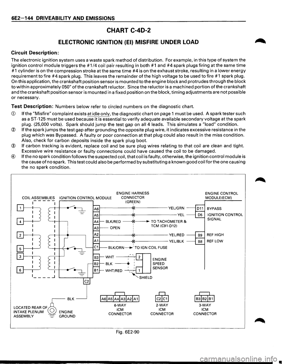
Circuit Description:
The electronic ignition system uses a waste spark method of distribution. For example, in this type of system the
ignition
control module triggers the # 1/4 coil pair resulting in both # 1 and #4 spark plugs firing at the same time
# 1 cylinder is on the compression stroke at the same time #4 is on the exhaust stroke, resulting in a lower energy
requirement
to fire #4 spark plug. This leaves the remainder of the high voltage to be used to fire #1 spark plug.
On this application, the crankshaft position sensor is mounted to the engine block and protrudes through the block
to within approximately 050" of the crankshaft reluctor. Since the reluctor is a machined portion of the crankshaft
and the crankshaft position sensor is mounted in a fixed position on the
block, timing adjustments are not possible
or necessary.
Test Description: Numbers below refer to circled numbers on the diagnostic chart.
CD If the "Misfire" complaint exists at idle only, the diagnostic chart on page 1 must be used. A spark tester such
as a ST-125 must be used because it is essential to verify adequate available secondary voltage at the spark
plug. (25,000 volts). Spark should jump the test gap on all 4 leads. This simulates a "load" condition.
® If the spark jumps the test gap after grounding the opposite plug wire, it indicates excessive resistance in the
plug which was Bypassed. A faulty or poor connection at that plug could also result in the miss condition.
Also, check for carbon deposits inside the spark plug boot.
® If carbon tracking is evident, replace coil and be sure plug wires relating to that coil are clean and tight.
Excessive
wire resistance or faulty connections could have caused the coil to be damaged.
® If the no spark condition follows the suspected coil, that coil is faulty, otherwise, the ignition control module is
the cause
of no spark. This test could also be performed by substituting a known good coil for the one causing
the no spark condition.
COIL ASSEMBLIES IGNITION CONTROL MODULE
ENGINE HARNESS
CONNECTOR
(GREEN) -----
:TI '--+I -l-----,
I
:TI
~
~--------~~-----------YE~GRN
~--------~~--------------VEL ' BLK/RED ------«--TO TACHOMETER &
OPEN ' TCM (C91-D12)
~--------~~-----------YE~RED
1------------((-----------YE~BLK ' BLK/ORN_.' TO IGN COIL FUSE
ENGINE SPEED
1 SENSOR
~SHIELD
IAsiAsii4ibiA21A11
6-WAY ICM
CONNECTOR
Fig. 6E2-90
lcik,l
2-WAY ICM
CONNECTOR ENGINE
CONTROL
MODULE(ECM)
BYPASS
IGNITION CONTROL
SIGNAL
REF HIGH
REF LOW
I
BJIB2I~1I
3-WAY ICM
CONNECTOR
•
Page 858 of 1928
6E2-162 DRIVEABILITY AND EMISSIONS
CHART C-10
AIR CONDITIONING (A/C) SYSTEM FUNCTIONAL CHECK
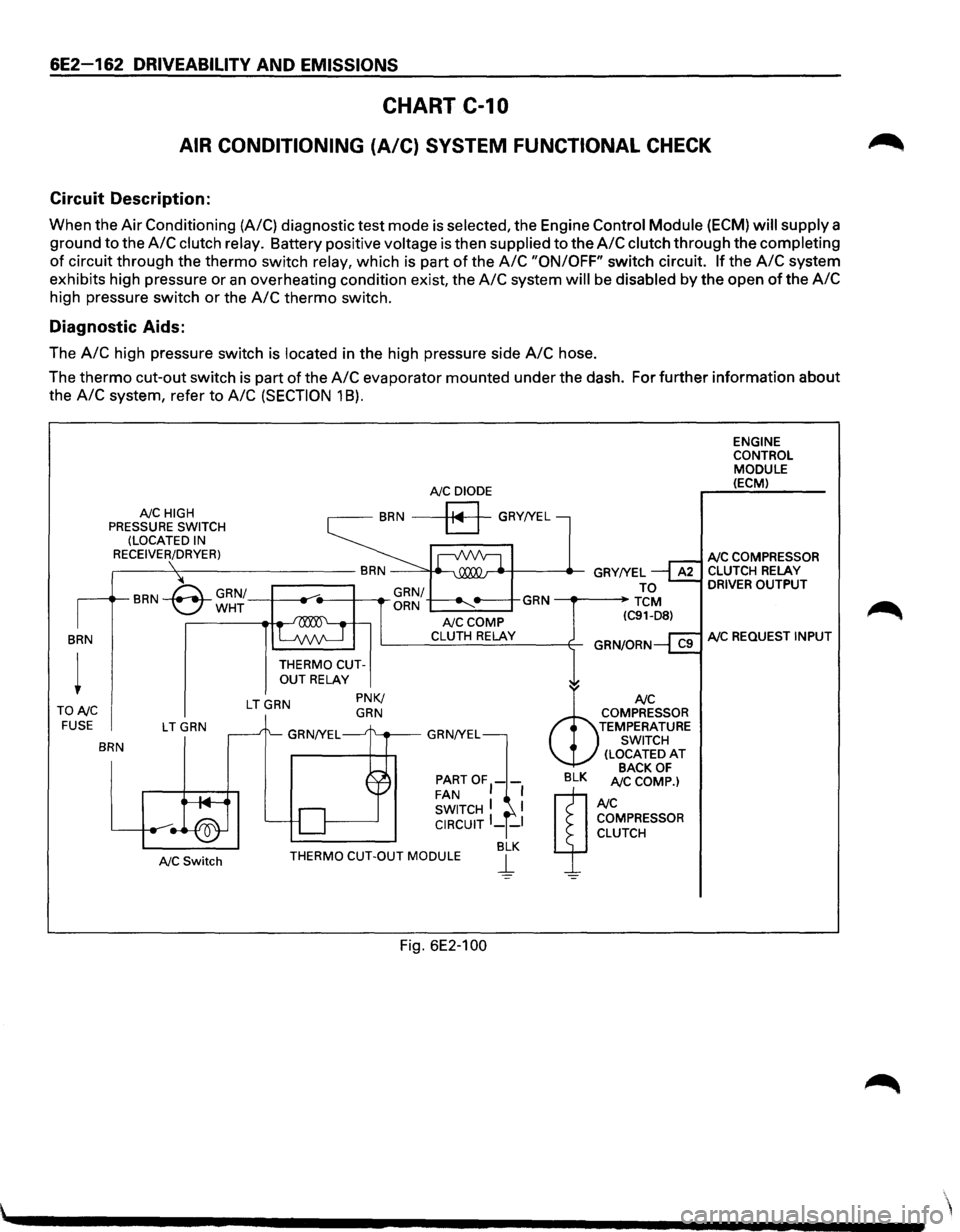
Circuit Description:
When the Air Conditioning (A/C) diagnostic test mode is selected, the Engine Control Module (ECM) will supply a
ground to the
A/C clutch relay. Battery positive voltage is then supplied to the A/C clutch through the completing
of circuit through the thermo switch relay, which is part of the A/C "ON/OFF" switch circuit. If the A/C system
exhibits high pressure or
an overheating condition exist, the A/C system will be disabled by the open of the A/C
high pressure switch or the A/C thermo switch.
Diagnostic Aids:
The A/C high pressure switch is located in the high pressure side A/C hose.
The
thermo cut-out switch is part of the A/C evaporator mounted under the dash. For further information about
the
A/C system, refer to A/C (SECTION 1 8).
BRN
TONC FUSE
NC HIGH
PRESSURE SWITCH
(LOCATED IN
RECEIVER/DRYER)
LTGRN
BRN
NC Switch
NC DIODE
BRN a GRY!YEL
THERMO CUTOUT RELAY
LTGRN PNK/ GRN
NCCOMP CLUTH RELAY
PARTOF1-FAN I SWITCH I I CIRCUIT I __ I
BLK THERMO CUT-OUT MODULE j_
Fig. 6E2-100
ENGINE
CONTROL
MODULE (ECM)
NC COMPRESSOR CLUTCH RELAY DRIVER OUTPUT
NC REQUEST INPUT
Page 894 of 1928
7 A-22 AUTOMATIC TRANSMISSION (4l30-E)
TEST DRIVING
Some 4L30-E automatic transmission complaints
vehicles will require a test drive as a part of the
diagnostic procedure.
Some codes will not set
unless the vehicle is moving. The purpose of the
test
drive is to duplicate the customer's complaint
condition and set a current Transmission Control
Module (TCM) trouble code. Perform this
procedure before each 4L30-E automatic trans
mission repair, and again after repairs are made.
IMPORTANT:
• Duplicate the condition under which the
customer's complaint was observed.
• Depending on the complaint, line pressure
gauge and the
TECH1 scan tool may be
required
during the test drive.
• During the test drive, it is important to record
all necessary data from the areas being
monitored, for use in diagnosis. Also listen for
and note any unusual noises.
The
following procedure should be used to test
drive 4L30-E automatic
transmission complaint
vehicles:
1. Turn the ignition ON without starting the
engine. Check
that the "CHECK TRANS" lamp
comes on for approximately 2 to 3 seconds
and then goes
out and remains out.
• If the lamp is flashing, GOTO CHECK
TRANS INDICATOR (on page 7A-46).
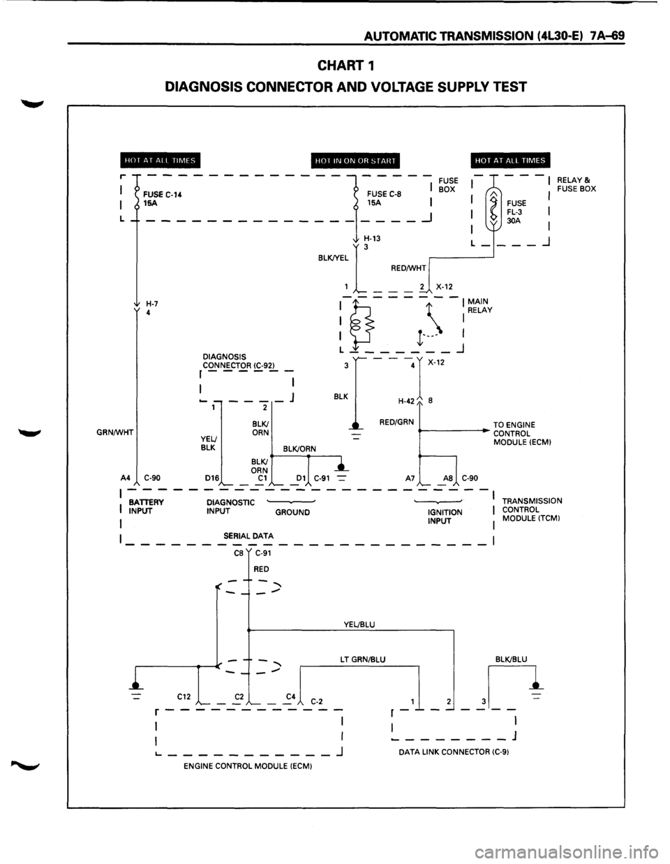
• If no serial data is present, see Chart 1:
DIAGNOSTIC CONNECTOR AND VOLTAGE
SUPPLY TEST (on page 7A-69 and 7A-70).
• If the lamp stays ON or stays OFF, GOTO
"CHECK TRANS"
CHECK (on page 7A-48).
NOTE:
Remember that, when TECH1 is connected,
line pressure will be at maximum during shifts.
2. Drive the vehicle. During the test drive be sure
that the transmission achieves normal
operating temperature (approx. 20 minutes) ..
Allow the transmission to go through all of 1ts
gear ranges, checking shift timing and
firmness.
Duplicate the owner's complaint
condition as closely as possible during the test
drive.
3. If, during the test drive, the "CHECK TRANS"
lamp comes on, use the TECH1 to check for
trouble codes.
4. If, during the test drive, a problem is felt, but
the "CHECK TRANS" lamp does not come on
and
no trouble codes are present, drive the
vehicle with the TCM disconnected (manually
shifting the vehicle).
•
In Manual L, the vehicle operates in first
gear.
• In Manual 2, the vehicle operates in third
gear.
• In Manual 3 or "D", the vehicle operates in
fourth gear.
If the problem still exists with the TCM
disconnected, refer
to the MECHANICAL/
HYDRAULIC DIAGNOSIS
in this Section.
5. If no problem has been found at this point,
check
all underhood connections that supply
power to the TCM and ignition fuses.
Physically and visually inspect all the TCM
harness connectors
for loose or corroded
terminals. Inspect the TCM ground points.
•
Page 920 of 1928
7 A-48 AUTOMATIC TRANSMISSION (4L30-E)
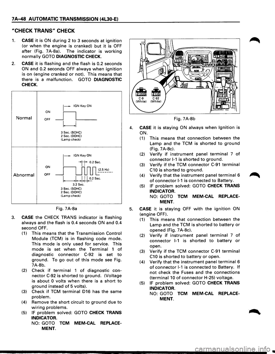
"CHECK TRANS" CHECK
1. CASE it is ON during 2 to 3 seconds at ignition
(or when the engine is cranked) but it is OFF
after (Fig. 7A-8a). The indicator is working
normally GOTO DIAGNOSTIC CHECK.
2. CASE it is flashing and the flash is 0.2 seconds
ON and 0.2 seconds OFF always when ignition
is on (engine cranked or not). This means that
there is a malfunction. GOTO DIAGNOSTIC
CHECK.
Normal
Abnormal
~-IGN Key ON
ON
II
OFF __j l___
~
3 Sec. (SOHC) 2 Sec. (OOHC) (Lamp check)
1-
IGN Key ON
il 0.2Sec.
oN 11 n n n ~~--s_ ~~)-_. OFF __j u u u l:
I. .I. .1.11. 0.2
Sec.
3.2 Sec. 3 Sec. (SOHC) 2 Sec. (OOHC) (Lamp check)
Fig. 7A-8b
4. CASE it is staying ON always when Ignition is
ON.
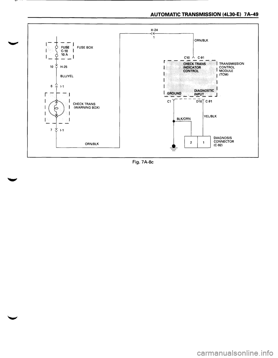
(1) This means that connection between the
Lamp and the TCM is shorted to ground
(Fig. 7 A-8c).
(2) Verify if instrument panel terminal 7 of
connector 1-1 is shorted to ground.
(3) Verify if the TCM connector C-91 terminal
C10 is shorted to ground.
(4) Verify that the instrument panel terminal 6
of connector 1-1 is connected to Battery.
(5) IF problem solved: GOTO CHECK TRANS
INDICATOR.
NO: GOTO TCM MEM-CAL REPLACE
MENT.
Fig. 7A-8a 5. CASE it is staying OFF with the ignition ON
(engine OFF). 3. CASE the CHECK TRANS indicator is flashing
always and the flash is 0.4 seconds ON and 0.4
second OFF.
(1) This means that the Transmission Control
Module (TCM) is in flashing code mode.
This mode is only used for service. This
mode is set when the Terminal 1 of
diagnostic connector C-92 is set to
ground. To go out of this mode see Fig.
7A-8b.
(2) Check
if terminal 1 of diagnostic con
nector C-92 is shorted to ground. (Voltage
is
about 0 volts when there is a short to
ground instead of 5 volts).
(3) Check if TCM terminal 016 has the same
problem.
(4) Remove the short circuit to ground due to
wiring problems.
(5) IF problem solved: GOTO CHECK TRANS
INDICATOR.
NO: GOTO TCM MEM-CAL REPLACE
MENT.
(1) This means that connection between the
Lamp and the TCM is shorted to battery or
opened (Fig. 7 A-8c).
(2) Verify if instrument panel terminal 7 of
connector 1-1 is shorted to battery or
open.
(3)
Verify if the TCM connector C-91 terminal
C1 0 is shorted to battery or open.
(4)
Verify that the instrument panel terminal 6
of connector 1-1 is connected to Battery. If
not check the Fuses and the connections
(terminal 10 of connector H-25) voltage.
(5) IF problem solved: GOTO CHECK TRANS
INDICATOR.
NO: GOTO TCM MEM-CAL REPLACE
MENT.
Page 921 of 1928
FUSE BOX
10 I H-25
BLU!YEL
6 t_l-1
r -~-~
I I CHECK TRANS I I (WARNING BOX)
I I
I
7 1-1
ORN/BLK
AUTOMATIC TRANSMISSION (4l30-E) 7 A-49
H-24
Fig. 7A-8c
ORN/BLK
C10 C-91
f - - -CHiCKTRANS--~ TRANSMISSION I tNOICAfiOR I CONTROL
I CONTROL MODULE I (TCM)
I I
I
I .. DIAGNOSTIC I _GROUNI',): _ _ t~U!_ ..:;;. .J
C1
BLK/ORN
D16 C-91
YEL!BLK
DIAGNOSIS
CONNECTOR
(C-92)
Page 941 of 1928
AUTOMATIC TRANSMISSION (4L30-E) 7 A-69
CHART 1
DIAGNOSIS CONNECTOR AND VOLTAGE SUPPLY TEST
HOf AT All TIMES
r
L
GRN/WHT
FUSE C-14 15A
H-7 4
A4 C-90 DIAGNOSIS
CONNECTOR
(C-92) r------
1 I
----J 2
BLKI ORN
HOT IN ON OR START
FUSE C-8
15A I
I
__ _I
FUSE BOX
HOT AT ALL TIMES
---
l
A FUSE FL-3 30A
I I
I
I
H-13
BLKJYEL
1
[_ --
RED/WHT
L-___ _j
2
X-12
:1?.---- -:~t~v
I }-I t·---I L _______ _j
---r-12
H-42/o 8
3
BLK
RED/GRN
""--------i~ TO ENGINE
..- CONTROL
MODULE
(ECM)
YELl
BLK BLK!ORN
D16
BLKI
ORN
Cl Dl C-91 A7 AS C-90
RELAY& FUSE BOX
~------------------------BATTERY DIAGNOSTIC · · I
I INPUT INPUT GROUND IGNITION I
I INPUT I
TRANSMISSION
CONTROL MODULE
(TCM)
I SERIAL DATA
------------------------1 CB C-91
RED
YEL/BLU
L T GRN/BLU BLKIBLU
,_1_, ~n
I I ________ J
C12 C-2 r------------
1 I
I I
1...--------_J DATA LINK CONNECTOR (C-9)
ENGINE CONTROL MODULE (ECM)
Page 942 of 1928
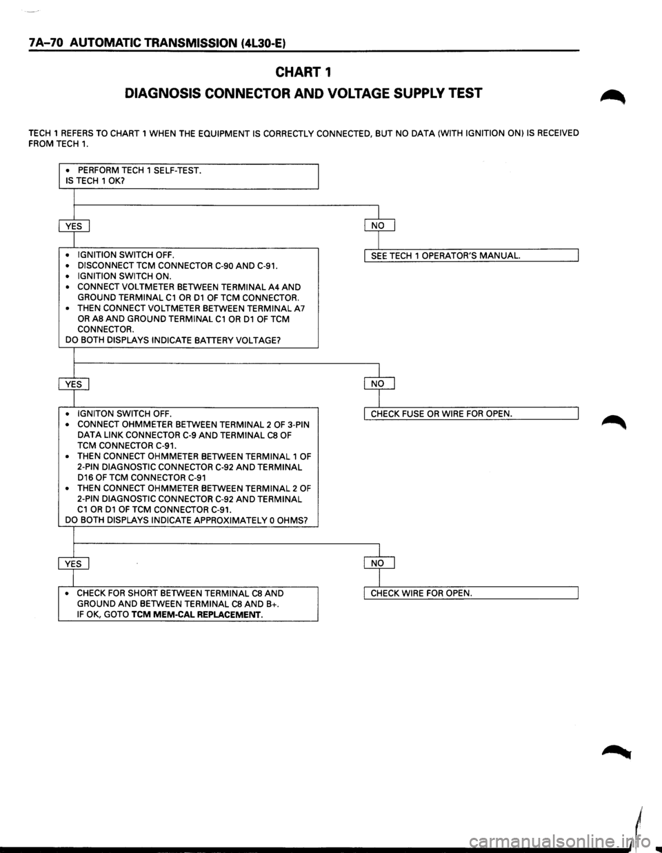
7A-70 AUTOMATIC TRANSMISSION (4L30-E)
CHART 1
DIAGNOSIS CONNECTOR AND VOLTAGE SUPPLY TEST
TECH 1 REFERS TO CHART 1 WHEN THE EQUIPMENT IS CORRECTLY CONNECTED, BUT NO DATA (WITH IGNITION ON) IS RECEIVED
FROM TECH 1.
• PERFORM TECH 1 SELF-TEST . IS TECH 1 OK?
~ ~
• IGNITION SWITCH OFF . I SEE TECH 1 OPERATOR'S MANUAL. I • DISCONNECT TCM CONNECTOR C-90 AND C-91 .
• IGNITION SWITCH ON .
• CONNECT VOLTMETER BETWEEN TERMINAL A4 AND GROUND TERMINAL C1 OR D1 OF TCM CONNECTOR.
•
THEN CONNECT VOLTMETER BETWEEN TERMINAL A7 OR AS AND GROUND TERMINAL C1 OR D1 OF TCM
CONNECTOR.
DO BOTH DISPLAYS INDICATE
BATTERY VOLTAGE?
+ ~ • IGNITON SWITCH OFF. I CHECK FUSE OR WIRE FOR OPEN. I • CONNECT OHMMETER BETWEEN TERMINAL 2 OF 3-PIN DATA LINK CONNECTOR C-9 AND TERMINAL CS OF
TCM CONNECTOR C-91.
•
THEN CONNECT OHMMETER BETWEEN TERMINAL 1 OF
2-PIN DIAGNOSTIC CONNECTOR C-92 AND TERMINAL D16 OF TCM CONNECTOR C-91
• THEN CONNECT OHMMETER BETWEEN TERMINAL 2 OF 2-PIN DIAGNOSTIC CONNECTOR C-92 AND TERMINAL C1 OR D1 OF TCM CONNECTOR C-91.
DO BOTH DISPLAYS INDICATE APPROXIMATELY 0 OHMS?
~ ~ • CHECK FOR SHORT BETWEEN TERMINAL CS AND I CHECK WIRE FOR OPEN. I GROUND AND BETWEEN TERMINAL CS AND B+. IF OK, GOTO TCM MEM-CAL REPLACEMENT.
____________ _,,(
Page 962 of 1928
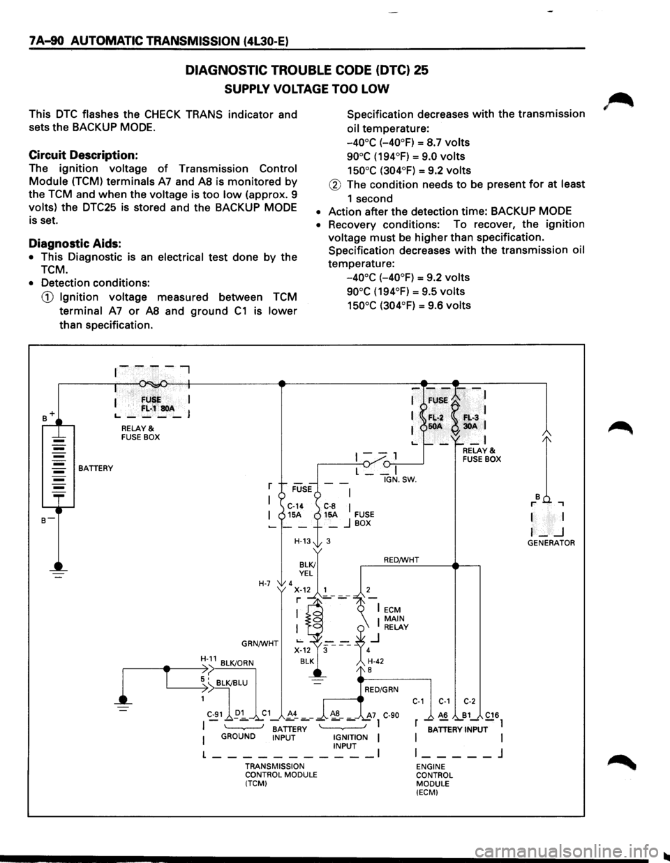
7 A-90 AUTOMATIC TRANSMISSION (4L30-E)
DIAGNOSTIC TROUBLE CODE (DTC) 25
SUPPLY VOLTAGE TOO LOW
This DTC flashes the CHECK TRANS indicator and
sets the BACKUP
MODE.
Specification decreases with the transmission
oil temperature:
Circuit Description:
-40°C (-40°F) = S.7 volts
90°C (194°F) = 9.0 volts
150°C (304°F) = 9.2 volts The ignition voltage of Transmission Control
Module (TCM) terminals A7 and AS is monitored by
the TCM and when the voltage is too low (approx. 9
volts) the DTC25 is stored and the BACKUP MODE
is set.
@ The condition needs to be present for at least
1 second
• Action after the detection time: BACKUP MODE
Diagnostic Aids:
• This Diagnostic is an electrical test done by the
TCM.
• Recovery conditions: To recover, the ignition
voltage must be higher than specification.
Specification decreases
with the transmission oil
temperature:
-40°C (-40°F) = 9.2 volts
90°C (194°F) = 9.5 volts
150°C (304°F) = 9.6 volts
• Detection conditions:
CD Ignition voltage measured between TCM
terminal A7 or AS and ground C1 is lower
than specification .
. · fU I
I '
f:L;~soA L., ____ J
RELAY & FUSE BOX
1--, {)-:,.--____..J BATTERY
l
T
L __ I
r
I C-14 C-8 I I 15A 15A FUSE -__ + _ j BOX
H-13t 3
H-7 'x~.~~'---7 r ]_-
GRN/WHT
BATTERY I GROUND INPUT IGNITION I INPUT I
L-----------TRANSMISSION
CONTROL MODULE
(TCM) IGN.SW.
RED/WHT
C-1 C-1 C-2
A6 B1 C16
r -;ATTERV INPUT-l
I
I l _____ j
ENGINE
CONTROL MODULE
(ECM)
I I
I-_j GENERATOR