fuse ISUZU TROOPER 1995 Repair Manual
[x] Cancel search | Manufacturer: ISUZU, Model Year: 1995, Model line: TROOPER, Model: ISUZU TROOPER 1995Pages: 1928
Page 963 of 1928
AUTOMATIC TRANSMISSION (4L30-E) 7A-91
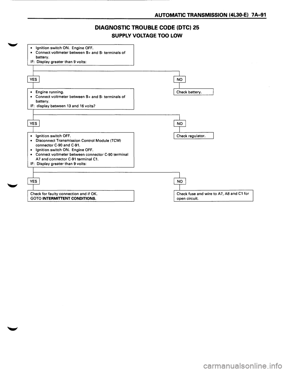
DIAGNOSTIC TROUBLE CODE (DTC) 25
SUPPLY VOLTAGE TOO LOW
• Ignition switch ON. Engine OFF.
• Connect voltmeter between B+ and B-terminals of battery. IF: Display greater than 9 volts:
•
Engine running.
• Connect voltmeter between B+ and B-terminals of battery.
IF: display between 13 and 16 volts?
• Ignition
switch OFF. • Disconnect Transmission Control Module (TCM)
connector C-90 and C-91. • Ignition switch ON. Engine OFF.
• Connect voltmeter between connector C-90 terminal A7 and connector C-91 terminal C1. IF: Display greater than 9 volts:
Check for faulty connection and if OK.
GOTO INTERMITTENT CONDITIONS.
Check fuse and wire to A7, AS and C1 for
open circuit.
Page 964 of 1928
7 A-92 AUTOMATIC TRANSMISSION (4L30-E)
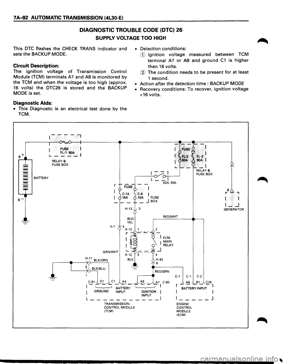
DIAGNOSTIC TROUBLE CODE (DTC) 26
SUPPLY VOLTAGE TOO HIGH
This DTC flashes the CHECK TRANS indicator and
sets the
BACKUP MODE.
Circuit Description:
The ignition voltage of Transmission Control
Module (TCM) terminals A7 and AS is monitored by
the TCM and when the voltage is too high (approx.
16 volts) the
DTC26 is stored and the BACKUP
MODE is set.
Diagnostic Aids:
• This Diagnostic is an electrical test done by the
TCM.
BATTERY
I FUSE I
L..-FL·1~A-I
RELAY & FUSE BOX
r
I
I
H-7
GRN/WHT
H-11 BLK/ORN
• Detection conditions:
CD Ignition voltage measured between TCM
terminal
A7 or AS and ground C1 is higher
than 16 volts.
® The condition needs to be present for at least
1 second.
• Action after the detection time : BACKUP MODE
• Recovery conditions: To recover, ignition voltage
<16
volts.
-F~;K--:
Fl:.-2 F•. L·3 50A 3DA 1
-_I
1--1 (1-,,--...----J L __ I
IGN.SW.
C-8 I 15A FUSE _ j BOX
3
RED/WHT
RELAY & FUSE BOX
r 1
I-..J GENERATOR
1
,-----------e-T ~:>( BLK/BLU
~ I RED/GRN
1
C-91 ~p:!_ C1 !-~ _ _ ~8-_ A7 C-90
C-1 C-1 C-2
I - - - -BATTER~ - - - -I
I GROUND INPUT IGNITION I INPUT l ___________ l
TRANSMISSION
CONTROL MODULE
(TCM)
_ A6 _B1_ C16
r BATTERY INPUT I I I
l _____ j
ENGINE
CONTROL
MODULE (ECM)
Page 996 of 1928
7A-124 AUTOMATIC TRANSMISSION (4L30-E)
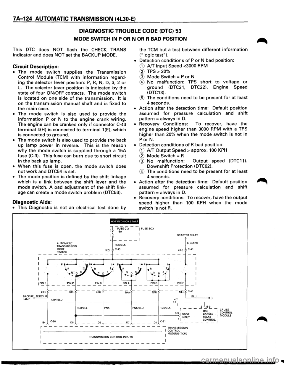
DIAGNOSTIC TROUBLE CODE (DTC) 53
MODE SWITCH IN P OR N OR R BAD POSITION
This DTC does NOT flash the CHECK TRANS
indicator and does NOT set the BACKUP MODE.
Circuit Description:
• The mode switch supplies the Transmission
Control Module (TCM) with information regard
ing
the selector lever position: P, R, N, D, 3, 2 or
L. The selector lever position is indicated by the
state
of four ON/OFF contacts. The mode switch
is located on one side of the transmission. It is
on
the transmission manual shaft and is fixed to
the main case.
• The mode switch is also used to provide the
information P or N to the engine crank wiring.
The engine can be cranked only if connector C-43
terminal 4(H) is connected to terminal 1(E), which
is connected to ground.
• The mode switch is also used to provide the back
up lamp power in reverse. This is the reason
why the mode switch is supplied through a 15A
fuse
(C-3). This fuse can burn due to short circuit
in the back up lamp.
•
When this fuse is open, the mode switch does
not work and DTC54 is set.
• The mode position is defined by the shift linkage
which is a link between the shift lever and the
mode switch. A bad adjustment of the shift link
age can create a mode switch problem (DTC53).
Diagnostic Aids:
• This Diagnostic is not an electrical test done by
the TCM but a test between different information
("logic test").
•
Detection conditions of P or N bad position:
CD A/T Input Speed <3000 RPM
0 TPS > 20%
@ Mode Switch = P or N
® No malfunction: TPS short to voltage or
ground (DTC21, DTC22), Engine Speed
(DTC13).
® The conditions need to be present for at least
4 seconds.
• Action after the detection time: Default position
assumed for pressure calculation and shift
pattern =always in D.
• Recovery Conditions: To recover, have the
engine speed higher than 3000 RPM with a TPS
higher than 20% when the mode switch is not in
PorN.
• Detection conditions of R bad position:
CD A/T Output Speed> approx. 100 KPH
0 Mode Switch= R
@ No malfunction: Output speed (DTC11).
Downshift Protection (DTC62).
® The conditions need to be present for at least
4 seconds.
• Action aft,:H the detection time: Default position
assumed for pressure calculation and shift
pattern = always in D.
• Recovery conditions: To recover, have the output
speed hi~1her than 100 KPH when the mode
switch is not R.
'''·"'·'lllfHJi'.!d'
1
-FUSe C-3 --~ FUSE BOX 16A I I STARTER RELAY
L _____ l I
~~J~Jr'~~~ION RED/BLK BLU/RED
I "'R 2 I R 2J 'R 2 • R 2J I
I '1o N D 3 ~/ l' N D 3 '( D ; / I
:~1-_-_-_~:-~ ~ ~'~t ~-: ~"~\_-_-~-_!!;~= = = ==~-: 2(F) "[ 6(C) 7(B) BIA) 3(G) liE) "'I C-43
BACKUP ( RED/BLU. . BLU ~It
LAMP ~'"""" "'""" "' e>
B4 '-- - -_Q6 - - - -_27 '-- - -_Q4 C-91 4 ~ - - -_co~T~L J
r - - - - - - - - - - - - - - - - - --- -- -1 TRANsM1ss1oN
I ~~~0RL~LITCM) I TRANSMISSION CONTROL INPUTS I
~-----------------------~
•
Page 998 of 1928
7A-126 AUTOMATIC TRANSMISSION (4L30-E)
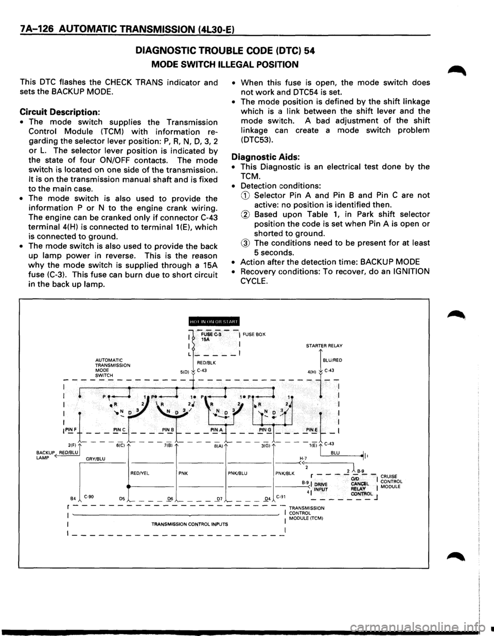
DIAGNOSTIC TROUBLE CODE (DTC) 54
MODE SWITCH ILLEGAL POSITION
This DTC flashes the CHECK TRANS indicator and
sets the BACKUP
MODE.
Circuit Description:
• The mode switch supplies the Transmission
Control Module (TCM) with information re
garding the
selector lever position: P, R, N, D, 3, 2
or L. The selector lever position is indicated by
the state of four ON/OFF contacts. The mode
switch is located on one side of the transmission.
It is on the transmission manual shaft and is fixed
to the main case.
• The mode switch is also used to provide the
information P or N to the engine crank wiring.
The engine can be cranked only if connector C-43
terminal 4(H) is connected to terminal 1(E), which
is connected to ground.
• The mode switch is also used to provide the back
up
lamp power in reverse. This is the reason
why the mode switch is supplied through a 15A
fuse (C-3). This fuse can burn due
to short circuit
in the back
up lamp. •
When
this fuse is open, the mode switch does
not work and DTC54 is set.
• The mode position is defined by the shift linkage
which is a link between the shift lever and the
mode switch. A bad adjustment of the shift
linkage can create a mode switch problem
(DTC53).
Diagnostic Aids:
• This Diagnostic is an electrical test done by the
TCM.
• Detection conditions:
CD Selector Pin A and Pin B and Pin C are not
active: no position is identified then.
@ Based upon Table 1, in Park shift selector
position the code is set when Pin A is open or
shorted to ground.
@ The conditions need to be present for at least
5 seconds.
• Action after the detection time: BACKUP MODE
•
Recovery Gonditions: To recover, do an IGNITION
CYCLE.
ii!Qpi.lifiiUI@ii!ll
•
Page 999 of 1928
AUTOMATIC TRANSMISSION (4L30-E) 7A-127
DIAGNOSTIC TROUBLE CODE (DTC) 54
MODE SWITCH ILLEGAL POSITION
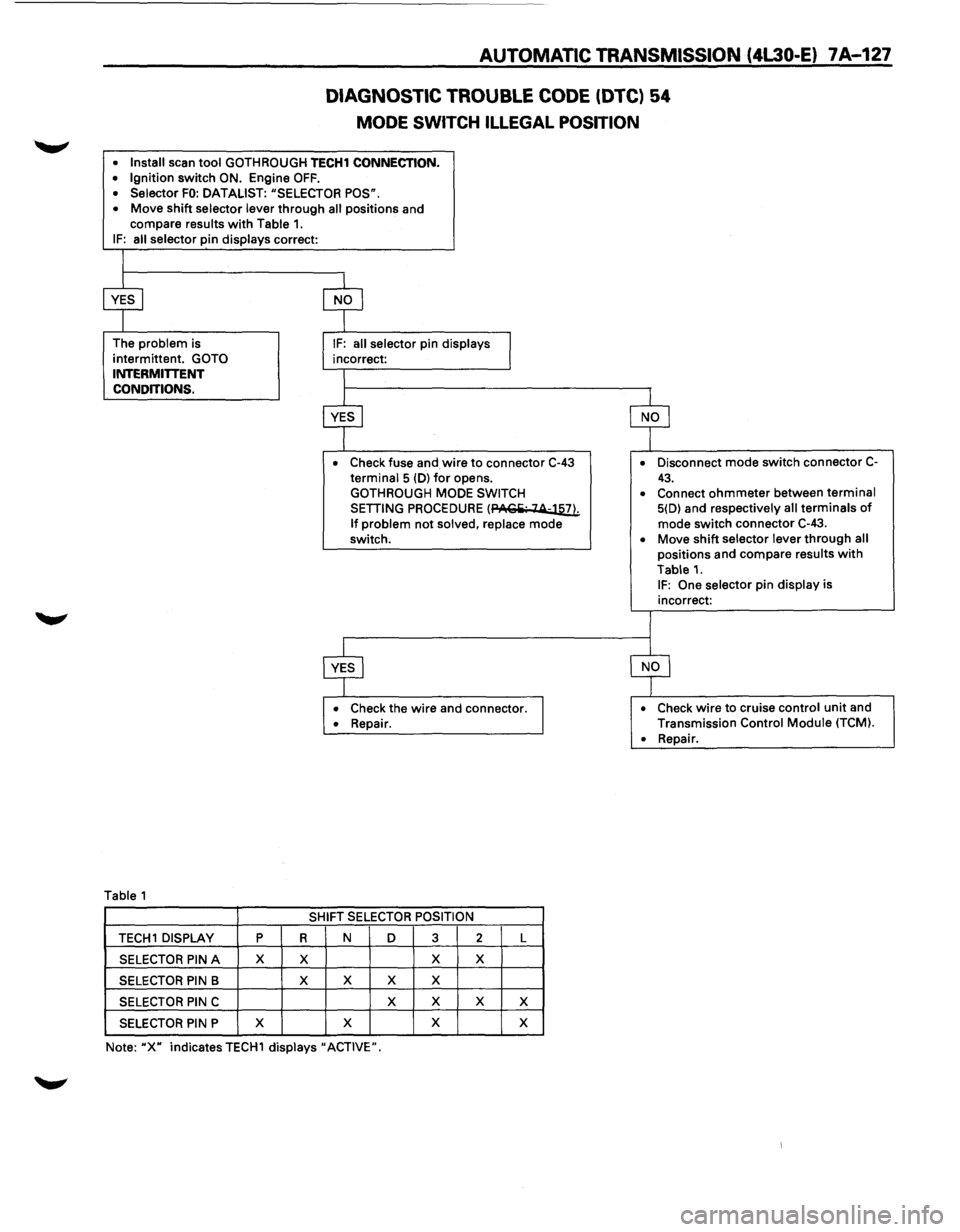
• Install scan tool GOTH ROUGH TECH1 CONNECTION. • Ignition switch ON. Engine OFF. • Selector FO: DATALIST: "SELECTOR POS".
• Move shift selector lever through all positions and
compare results with Table 1. IF: all selector pin displays correct:
The
problem is
intermittent.
GOTO INTERMITTENT
CONDITIONS.
Table 1
• Check fuse and wire to connector C-43 terminal 5 (D) for opens.
GOTHROUGH MODE SWITCH
SETTING PROCEDURE (PACiii· 14-llli
If problem not solved, replace mode
switch.
• Check the wire and connector. • Repair.
SHIFT SELECTOR POSITION
TECH 1 DISPLAY p R N D 3 2 L
SELECTOR PIN A X X X X
SELECTOR PIN B X
X X X
SELECTOR PIN C X
X X X
SELECTOR PIN P X
X X
X
Note: "X" indicates TECH1 displays" ACTIVE". •
Disconnect
mode switch connector C-
43. • Connect ohmmeter between terminal 5(D) and respectively all terminals of mode switch connector C-43.
• Move shift selector lever through all positions and compare results with
Table 1. IF: One selector pin display is
incorrect:
• Check wire to cruise control unit and
Transmission Control Module (TCM).
•
Repair.
Page 1013 of 1928
AUTOMATIC TRANSMISSION (4L30-E) 7A-141
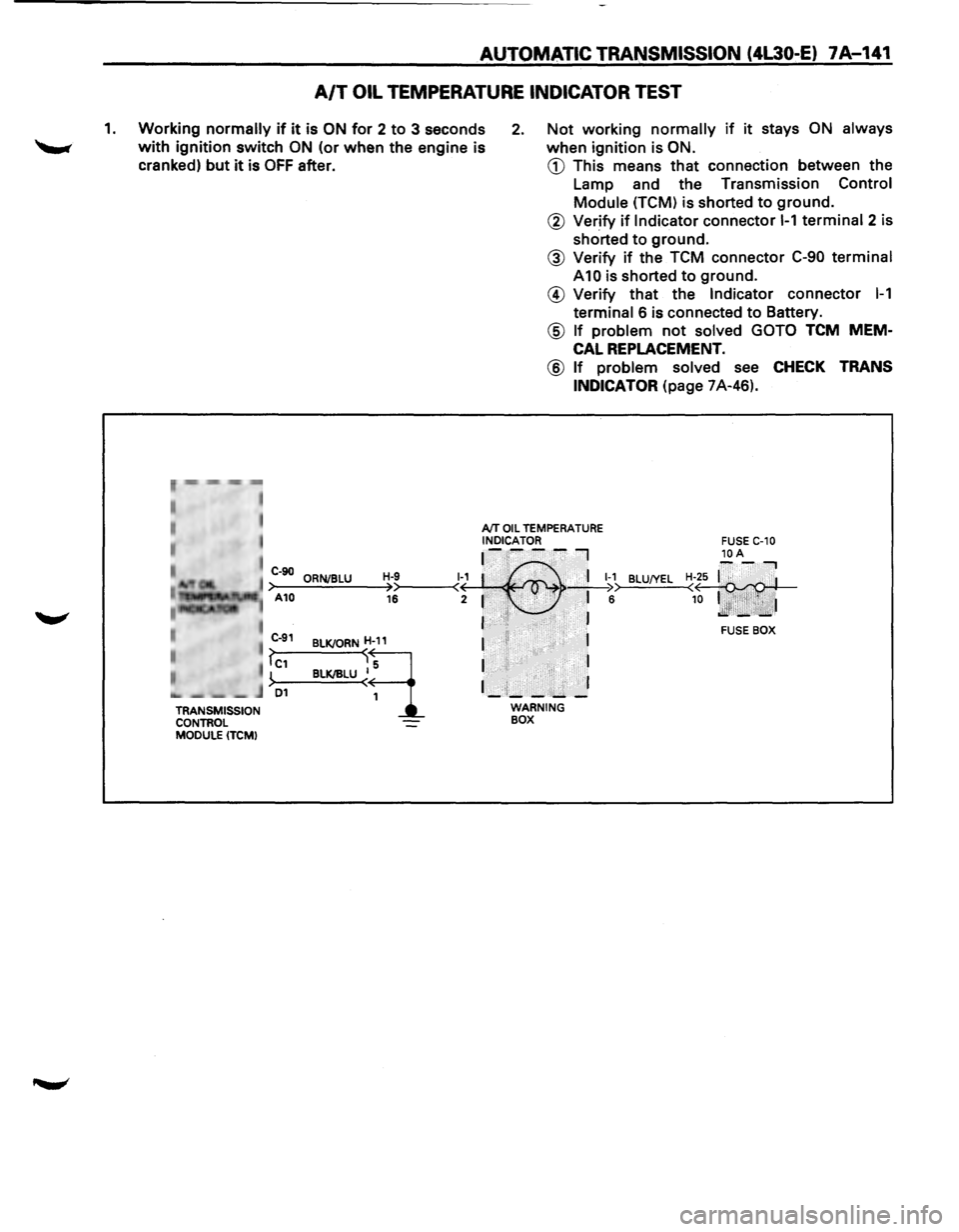
A/T OIL TEMPERATURE INDICATOR TEST
1. Working normally if it is ON for 2 to 3 seconds
with ignition switch ON (or when the engine is
cranked)
but it is OFF after.
2. Not working normally if it stays ON always
when ignition is ON.
CD This means that connection between the
Lamp and the Transmission
Control
Module (TCM) is shorted to ground.
r~,··mm -,-,~
• , I
I
TRANSMISSION
CONTROL
MODULE (TCM)
@ Verify if Indicator connector 1-1 terminal 2 is
shorted
to ground.
@ Verify if the TCM connector C-90 terminal
A10 is shorted to ground.
@ Verify that the Indicator connector 1-1
terminal 6 is connected to Battery.
@ If problem not solved GOTO TCM MEM
CAL REPLACEMENT.
@ If problem solved see CHECK TRANS
INDICATOR
(page 7A-46).
AfT OIL TEMPERATURE INDICATOR ~-~--~I
C-90 ORNJBLU H-9 1~1 :·' ,.· . 'I 1-1 >-A-10--=.:..;.;_;:,=-~>>----<( · , . ' >• • _;__I ;:. 16 2 1 . • .i· ,..:., • 6
I ·•'I• ·. . , . . J
BLU!YEL
BLKJORND
BLK/IILU ~~
I II 1
I I
1_:1;_-:....... _]
WARNING BOX
FUSE BOX
Page 1014 of 1928
7A-142 AUTOMATIC TRANSMISSION (4l30-E)
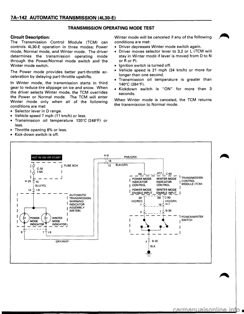
TRANSMISSION OPERATING MODE TEST
Circuit
Description:
The Transmission Control Module (TCM) can
controls 4L30-E operation in three modes: Power
mode, Normal mode, and Winter mode. The driver
determines the transmission operating mode
through the Power/Normal mode switch and the
Winter mode switch.
The
Power mode provides better part-throttle ac
celeration
by delaying part-throttle upshifts.
In Winter mode, the transmission starts in third
gear to reduce tire slippage on ice and snow. When
the driver selects Winter mode, the TCM overrides
the
Power or Normal mode. The TCM will enter
Winter mode only when all of the following
conditions are met:
• Selector lever in D range.
• Vehicle speed 7 mph ( 11 km/h) or less.
•
Transmission oil temperature 120°C (248°F) or
less.
•
Throttle opening 8% or less.
•
Kick-down switch is off.
Winter mode will be canceled if any of the following
conditions are met:
• Driver depresses Winter mode switch again.
• Driver moves selector lever to 3,2 or L (TCM will
stay in Winter mode if lever is moved from D to N
orR or P).
• Ignition switch is turned off.
• Vehicle speed is 21 mph (34 km/h) or more for
longer than one second.
• Transmission oil temperature is greater than
140°C (284·°F).
• Kickdown switch is "ON" for more than 3
seconds.
When Winter mode is canceled, the TCM returns
the transmission
to Normal mode.
HOT IN ON OR START H-9 PNK/GRN
.«19 u
'1----~ FUSEBOX C-10 I 7.5A I
I
____ J
H-25 v 10
lBLUIYEL
14 1-9
r--- - - --AUTOMATIC
I
I I TRANSMISSION
WARNING/
I INDICATOR I ASSEMBLY (METER)
I
I WINTER MODE _INOICATORJ
GRY/WHT
«~13~-BL-K/~G-R-N----]
89 - - -~ 11 C-90
I~POW'ERMOOE-WiNTER MODE 1 TRANSMISSION
INDICATOR INDICATOR I CONTROL I CONTROL CONTROL MODULE !TCMI
I POWER MODE WINTER MODE I _gN~~L[.!NPUT-E!:::J£-BLE INPUl.. I
88 r ----86 rC-90 VIO/RED VIO/GRN 7 16 H-7
3 t ----~ 1 B-30
--\~~~--:~~~~NTER
-T---~
};
•
Page 1016 of 1928
7A-144 AUTOMATIC TRANSMISSION (4L30-E)
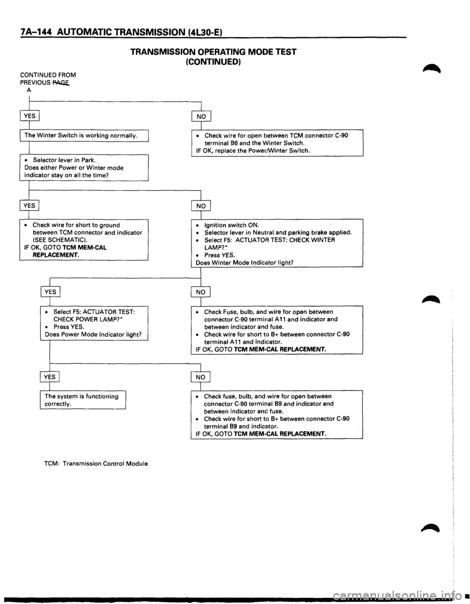
TRANSMISSION OPERATING MODE TEST
(CONTINUED)
CONTINUED FROM
PREVIOUS
PAGE. A
I
$
The Winter Switch is working normally.
I
• Selector lever in Park .
Does
either Power or Winter mode indicator stay on all the time?
I
$
• Check wire for short to ground
between
TCM connector and indicator (SEE SCHEMATIC).
IF OK, GOTO TCM MEM-CAL REPLACEMENT.
$
• Select F5: ACTUATOR TEST: CHECK POWER LAMP?"
• Press YES .
Does Power Mode Indicator light?
~
The system is functioning
J correctly.
TCM:
Transmission Control Module
$
• Check wire for open between TCM connector C-90 terminal 86 and the Winter Switch.
IF OK, replace the Power/Winter Switch.
$
• Ignition switch ON .
• Selector lever in Neutral and parking brake applied .
• Select F5: ACTUATOR TEST: CHECK WINTER
LAMP?"
• Press YES .
Does Winter Mode Indicator light?
I
$
• Check Fuse, bulb, and wire for open between
connector C-90 terminal A 11 and indicator and
between indicator and fuse.
• Check wire for short til 8+ between connector C-90
terminal A 11 and Indicator. IF OK, GOTO TCM MEM-CAL REPLACEMENT.
$
• Check fuse, bulb, and wire for open between
connector C-90 terminal 89 and indicator and
between indicator andl fuse.
• Check wire for short to 8+ between connector C-90 terminal 89 and indicator.
IF OK, GOTO TCM MEM-CAL REPLACEMENT.
•
Page 1024 of 1928
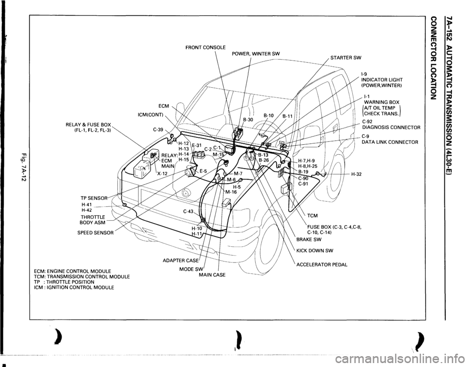
•
, cCi" -.J )> I .... N
RELAY
& FUSE BOX
(FL-1, FL-2, FL-3)
THROTTLE BODYASM SPEED SENSOR
ECM:
ENGINE CONTROL
MODULE
TCM:
TRANSMISSION CONTROL
MODULE
TP :THROTTLE
POSITION
ICM
: IGNITION CONTROL
MODULE
)
ECM
ICM(CONT) FRONT
CONSOLE
MODESW
MAIN
CASE
,}
~H-32
FUSE BOX
(C-3,
C-4,C-8,
C-10,
C-14)
BRAKE
SW
KICK DOWN
SW
ACCELERATOR PEDAL
1-9 INDICATOR LIGHT
(POWER, WINTER) 1-1 WARNING BOX (AfT
OIL
TEMP )
CHECK TRANS.
C-92 DIAGNOSIS CONNECTOR C-9 DATA
LINK CONNECTOR
}
(') 0 2
2 m a ::IJ r-0 (') !4 0 2
" t .... C1l N l> c: a s: !4 n -4 ::IJ l> 2 rA s: c;; rA 0 2 ~ ~ 0 I m
Page 1191 of 1928

CHASSIS ELECTRICAL 8-1
·SECTION 8
CHASSIS ELECTRICAL
'\f CAUTION: .
When fasteners are removed, always reinstall them at the same location from which they were removed.
If a fastener needs to be replaced, use the correct part number fastener for that application. If the correct
part number fastener is not
available, a fastener of equal size and strength (or stronger) may be used.
Fasteners that are not reused, and those requiring thread
locking compound, will be called out. The correct
torque
values must be used when installing fasteners that require it. If the above conditions are not
followed, parts or system damage could result.
CONTENTS
General Information .................................... 8-2
Notes for Working on Electrical
Items .................................................... 8-2
Symbols and Abbreviations ................. 8-8
Symbols ............................................ 8-8
Abbreviations ................................... 8-9
Parts for Electrical Circuit ..................... 8-10
Wiring ............................................... 8-10
Fuse .................................................. 8-11
Fusible Link ....................................... 8-12
Circuit Breaker ................................... 8-12
Relay ................................................. 8-12
Relay Specifications and
Configurations ................................ 8-13
Diode ................................................. 8-14
Connector ......................................... 8-15
Reading the Circuit Diagram ................ 8-17
Main Data and Specifications .................... 8-19
Bulb Specifications ................................ 8-19
Fuse,
Fusible Link and
Circuit Breaker Location ..................... 8-21
Fuse
Block Circuit .................................. 8-22
Reference Table of Fuse, Fusible
Link and Circuit Breaker ..................... 8-23
Relay Location ....................................... 8-27
Diode Location .......................................
8-28
Grounding Point .................................... 8-29
Reference Table ................................ 8-29
Location ............................................ 8-31
Cable Harness Routing .......................... 8-34
System Repair .............................................. 8-38
Start and Charging ................................ 8-38
Engine Control Module
(ECM) ................................................... 8-47
Headlight and Fog Light ........................ 8-58
Front Side Marker Light, Parking Light,
Taillight, License Plate Light and
Illumination Light .............................. 8-76
Stoplight and Rear Defogger .............. 8-92
Turn Signal Light, Hazard
Warning
Light, Cornering Light,
Backup
Light and Horn ..................... 8-106
Dome Light, Luggage room Light,
Courtesy Light, Map Light,
Seat Belt Switch and
Warning Buzzer ................................. 8-128
Power Door Lock ................................. 8-142
Power
Window .................................... 8-156
Cruise
Control ...................................... 8-172
Anti-Lock Brake
System (ABS) ........... 8-178
Rear
Wheel Anti-Lock Brake
System (RWAL) ................................. 8-185
Transmission
Control Module
(TCM) ................................................. 8-192
A/T Shift Lock ...................................... 8-200
Windshield
Wiper/Washer and
Rear
Wiper/Washer .......................... 8-205
Headlight wiper /washer ..................... 8-232
Audio, Auto Antenna,
Cigarette
Lighter and digital clock ... 8-246
Power Door Mirror ............................... 8-254
Anti-theft System ................................ 8-270
Meter and Warning/Indicator Light ... 8-288
A/T Shift Indicator ............................... 8-336
Heater and
Air Conditioning ............... 8-340
Sun
Roof ............................................... 8-346
Power Seat ........................................... 8-360
Seat
Heater .......................................... 8-37 4
Supplemental Restraint
System (SRS) -AIR BAG ................... 8-382