fuse ISUZU TROOPER 1995 Owner's Manual
[x] Cancel search | Manufacturer: ISUZU, Model Year: 1995, Model line: TROOPER, Model: ISUZU TROOPER 1995Pages: 1928
Page 468 of 1928
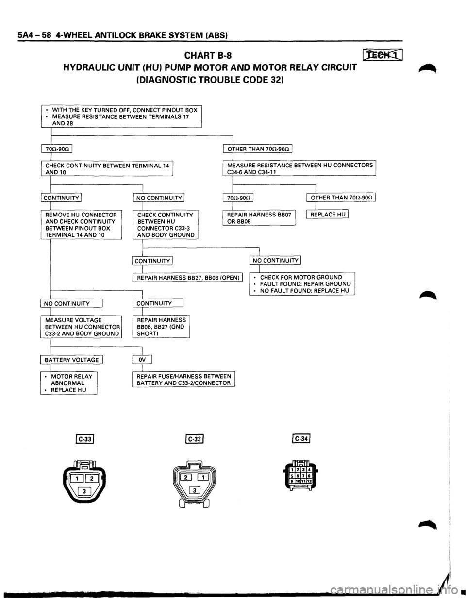
5A4-58 4-WHEEL ANTILOCK BRAKE SYSTEM (ABS)
CHART B-8 I):Eeti((l
HYDRAULIC UNIT (HU) PUMP MOTOR AND MOTOR RELAY CIRCUIT ~
(DIAGNOSTIC TROUBLE CODE 32)
• WITH THE KEY TURNED OFF, CONNECT PINOUT BOX
• MEASURE RESISTANCE BETWEEN TERMINALS 17 AND28
I 70n-9on I I OTHER THAN 70n-9on I
I
CHECK CONTINUITY BETWEEN TERMINAL 141 AND10 I MEASURE RESISTANCE BETWEEN HU CONNECTORS I C34-6 AND C34-11
I
I I I
CONTINUITY j NO CONTINUITY j 1 70(l-9ooJ I OTHER THAN 70n-9on I
I I I REMOVE HU CONNECTOR CHECK CONTINUITY I REPAIR HARNESS BB07 I I REPLACE HU I AND CHECK CONTINUITY BETWEEN HU OR BB08 BETWEEN PINOUT BOX
CONNECTOR C33-3 TERMINAL 14 AND 10 AND BODY GROUND
I
I
I CONTINUITY I NO CONTINUITY j
I I REPAIR HARNESS BB27, BB06 (OPEN) I • CHECK FOR MOTOR GROUND • FAULT FOUND: REPAIR GROUND
I • NO FAULT FOUND: REPLACE HU
NO CONTINUITY I CONTINUITY J
I MEASURE VOLTAGE REPAIR HARNESS
BETWEEN HU CONNECTOR BB06, BB27
(GND
C33-2 AND BODY GROUND SHORT)
BATTERYVOLTAGE I $
. MOTOR RELAY REPAIR FUSE/HARNESS BETWEEN I ABNORMAL BATTERY AND C33-2/CONNECTOR • REPLACE HU
•
Page 470 of 1928
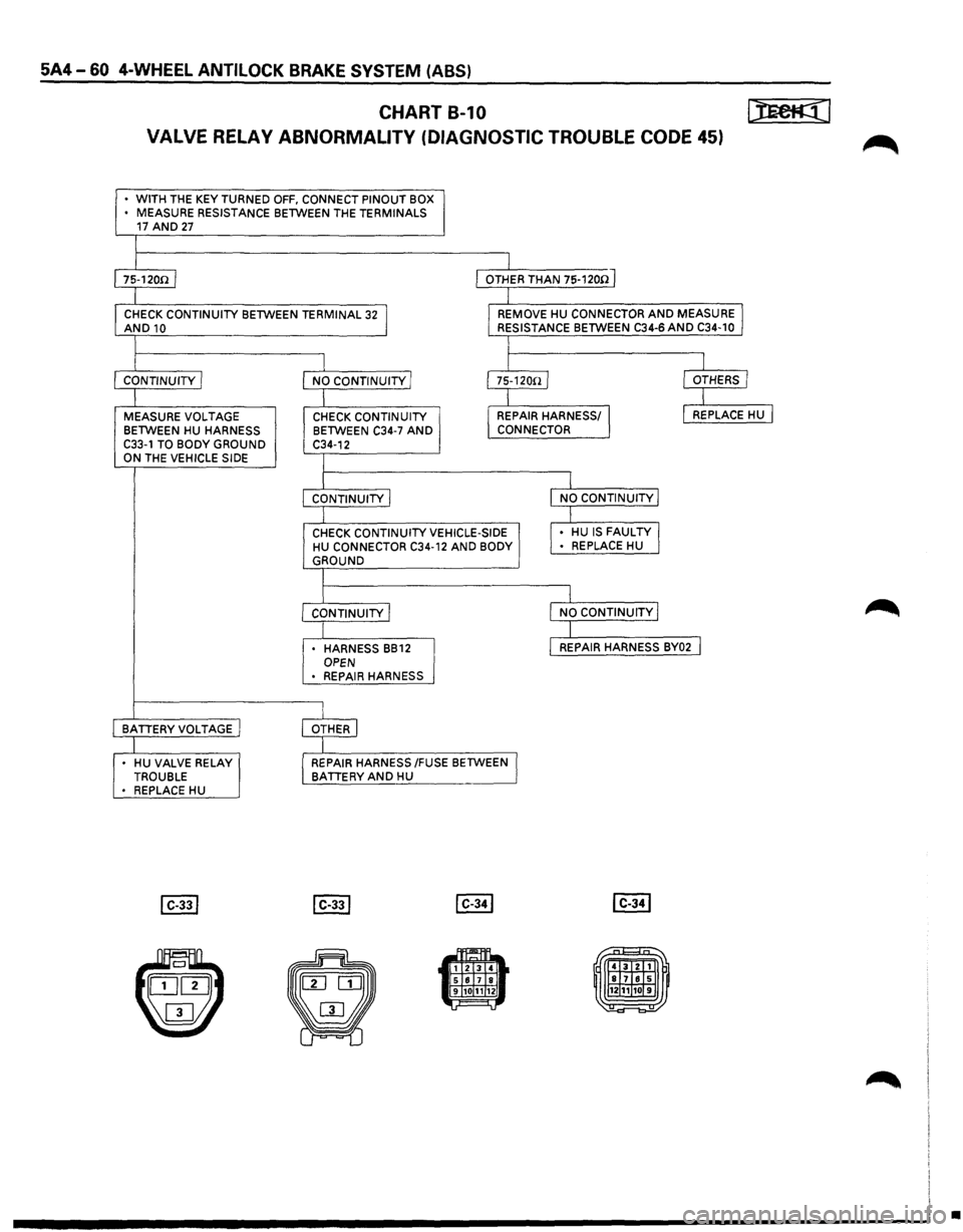
5A4-60 4-WHEEL ANTILOCK BRAKE SYSTEM (ABS)
CHART B-1 0 [):Ee@]
VALVE RELAY ABNORMALITY (DIAGNOSTIC TROUBLE CODE 45) ~
• WITH THE KEY TURNED OFF, CONNECT PINOUT BOX
• MEASURE RESISTANCE BETWEEN THE TERMINALS 17 AND 27
I 1s-12oo 1 I OTHER THAN 75-1200 J
I
CHECK CONTINUITY
BETWEEN TERMINAL 32 J AND10 I_ REMOVE HU CONNECTOR AND MEASURE I RESISTANCE BETWEEN C34-6 AND C34-10
I
I
I I
CONTINUITY I
NO CONTINUITY/ I75-120n/ I OTHERS I
I I
I
MEASURE
VOLTAGE CHECK CONTINUITY I REPAIR HARNESS/ J I REPLACE HU I
BETWEEN HU HARNESS BETWEEN C34-7 AND CONNECTOR
C33-1 TO BODY GROUND C34-12 ON THE VEHICLE SIDE I
I I CONTINUITY I l NO CONTINUITY I
I I
CHECK CONTINUITY VEHICLE-SIDE
,. HU IS FAULTY J HU CONNECTOR C34-12 AND BODY • REPLACE
HU GROUND
I
I I
CONTINUITY j I NO CONTINUITY I
I I • HARNESS BB12 l REPAIR HARNESS BY02 I OPEN
• REPAIR HARNESS
I BATTERY VOLTAGE j OTHER I
I
• HU VALVE RELAY I REPAIR HARNESS /FUSE BETWEEN I TROUBLE BATTERY AND HU • REPLACE HU
~1111 .. 1 2 3 4 5 617 8 9 101112 =
•
Page 502 of 1928
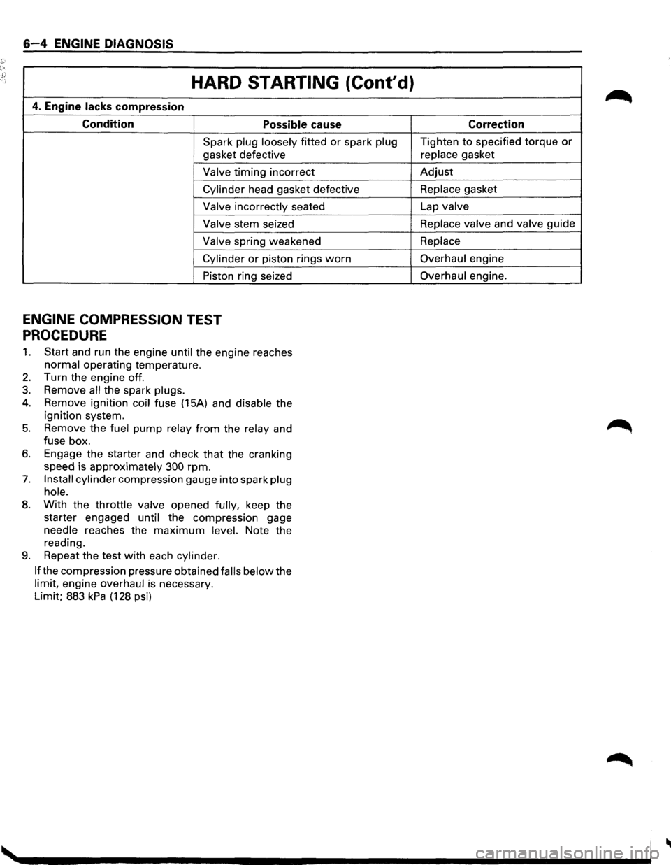
6-4 ENGINE DIAGNOSIS
HARD STARTING (Cont'd)
4. Engine lacks compression
Condition Possible cause
Spark plug loosely fitted or spark plug
gasket defective
Valve timing incorrect
Cylinder head gasket defective
Valve incorrectly seated
Valve stem seized
Valve spring weakened
Cylinder or piston rings worn
Piston ring seized
ENGINE COMPRESSION TEST
PROCEDURE
1. Start and run the engine until the engine reaches
normal operating temperature.
2. Turn the engine off.
3. Remove all the spark plugs.
4. Remove ignition coil fuse (15A) and disable the
ignition system.
5. Remove the fuel pump relay from the relay and
fuse box.
6. Engage the starter and check that the cranking
speed is approximately
300 rpm.
7. Install cylinder compression gauge into spark plug
hole.
8. With the throttle valve opened fully, keep the
starter engaged
until the compression gage
needle reaches the
maximum level. Note the
reading.
9. Repeat the test with each cylinder.
If
the compression pressure obtained falls below the
limit, engine overhaul is necessary.
Limit; 883
kPa (128 psi) Correction
Tighten
to specified torque or
replace gasket
Adjust
Replace gasket
Lap
valve
Replace valve
and valve guide
Replace
Overhaul engine
Overhaul engine.
Page 550 of 1928
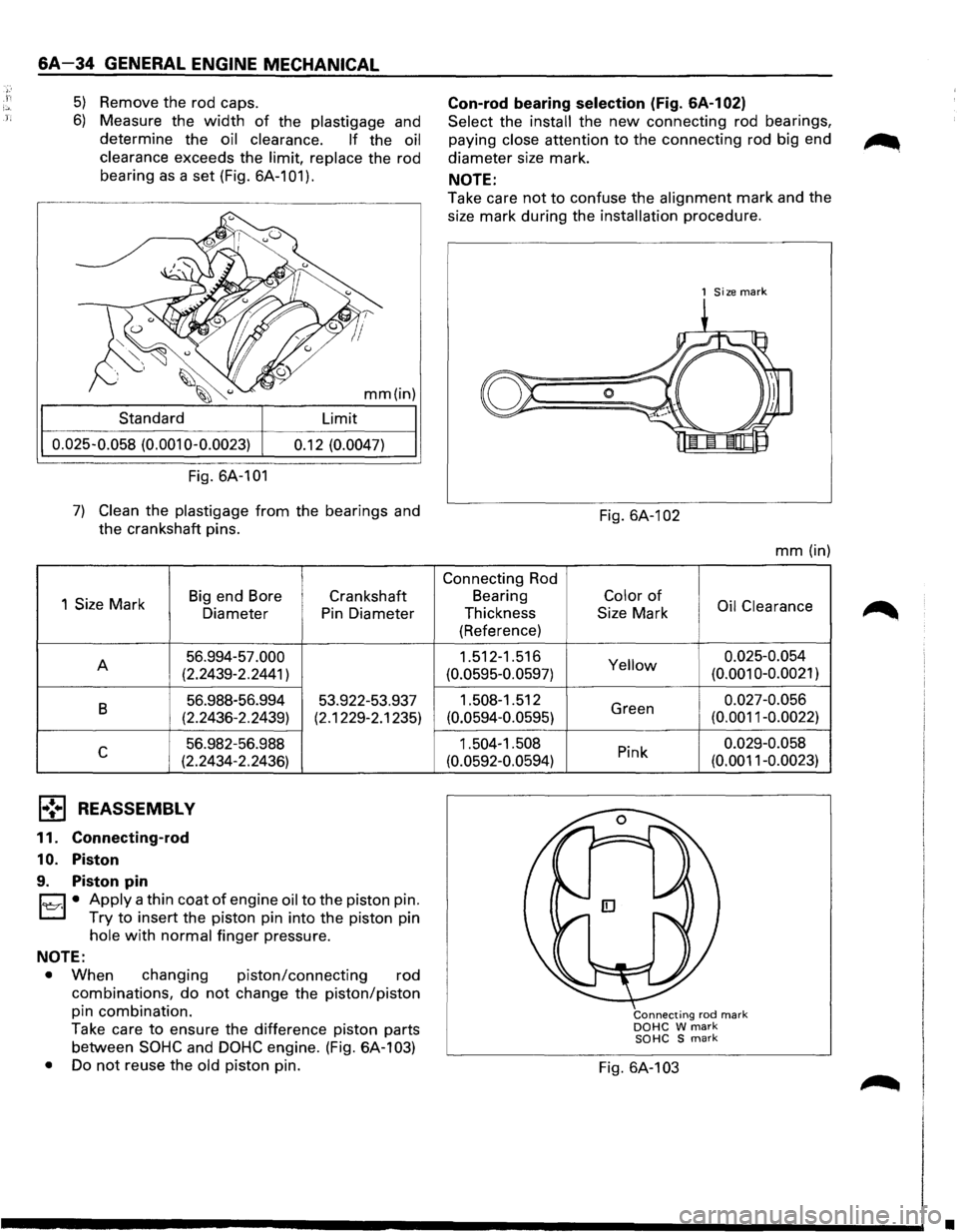
6A-34 GENERAL ENGINE MECHANICAL
5) Remove the rod caps.
6) Measure the width of the plastigage and
determine the
oil clearance. If the oil
clearance
exceeds the limit, replace the rod
bearing
as a set (Fig. 6A-101).
mm(in)
Standard Limit
0.025-0.058
(0.001 0-0.0023) 0.12 (0.0047)
Fig. 6A-101
7) Clean the plastigage from the bearings and
the crankshaft pins.
1
Size Mark Big
end Bore
Diameter
A 56.994-57.000
(2.2439-2.2441)
B 56.988-56.994
(2.2436-2.2439)
c 56.982-56.988
(2.2434-2.2436)
1,.!•1 REASSEMBLY
11. Connecting-rod
10. Piston
9. Piston pin
Crankshaft
Pin Diameter
53.922-53.937
(2.1229-2.1235)
D • Apply a thin coat of engine oil to the piston pin.
r..::::J Try to insert the piston pin into the piston pin
hole with normal finger pressure.
NOTE:
•
When changing piston/connecting rod
combinations,
do not change the piston/piston
pin combination.
Take care
to ensure the difference piston parts
between
SOHC and DOHC engine. (Fig. 6A-1 03)
• Do not reuse the old piston pin.
Con-rod bearing selection (Fig. GA-1 02)
Select the install the new connecting rod bearings,
paying
close attention to the connecting rod big end
diameter size mark.
NOTE:
Take care not to confuse the alignment mark and the
size mark during the
installation procedure.
Connecting Rod
Bearing
Thickness
(Reference)
1.512-1.516
(0.0595-0.0597)
1.508-1.512
(0.0594-0.0595)
1.504-1.508
(0.0592-0.0594)
1 Size mark
Fig. 6A-1 02
mm (in)
Color of Oil Clearance
Size Mark
Yellow 0.025-0.054 (0.001 0-0.0021)
Green 0.027-0.056
(0.0011-0.0022)
Pink 0.029-0.058
(0.0011-0.0023)
Connecting rod mark DOHC W mark SOHC S mark
Fig. 6A-103
•
Page 655 of 1928
ENGINE ELECTRICAL 601-1
SECTION 60
ENGINE ELECTRICAL
CONTENTS
Battery . . ..... . ...... . ... . .... . .... ..... .... . .... .. .... . .... . . ... . . . .... . . .. . . .... . ... . ... . .... . . .. ... . .... . . ... . ... . . .. . Section 601
Cranking System
........... ... . ... . .... . .... . . .... . .... .
. ... . . .... . .... . .... . . ... ...
.. .... . . ..... . .... . ......... ... Section 602
Charging System ..... .... . . .............. .... . .... . . .. .. . . ... . . ... . . ... . . ... . . ........ .... . . ..... .. .... . ... . .... . .. Section 603
Ignition System (V6 3.2L) .. .... ...... ...... .. .. .. .... ...... .... .. .... .... .... ...... ...... ...... .......... .... Section 6D4A
SECTION 601
BATTERY
CONTENTS
General Description ............................... 6D1-1
Diagnosis .............................................. 6D1-1
On-Vehicle Service ................................ 6D1-3
Battery Charging ................................ 6D1-3
Jump Starting .................................... 6D1-3
Removal and Installation of The Battery . . 6D1-4
Main Data and Specifications . . . . . . . . . . . . . . . . . . 6D1-4
GENERAL DESCRIPTION
There are six battery fluid caps at the top of the
battery. These are covered by a paper
label.
The battery is completely sealed except for the six
small vent holes at the side. These vent holes per
mit the escape of small amounts of gas generated
by the battery.
This type
of battery has the following advantages
over
conventional batteries:
1. There is no need to add water during the entire
service
life of the battery.
2. The battery protects itself against overcharging.
The battery
will refuse to accept an excessive
charge. (A
conventional battery will accept an excessive
charge,
resulting in gassing and loss of battery
fluid.)
3. The battery is much less vulnerable to self
discharge than a conventional type battery.
DIAGNOSIS
1. VISUAL INSPECTION
Inspect the battery for obvious physical damage,
such
as a cracked or broken case, which would per
mit electrolyte loss.
Replace
the battery if obvious physical damage is
discovered during inspection.
Check
for any other physical damage and correct it
as necessary. If not, proceed to Step 2.
2. HYDROMETER CHECK
There is a built-in hydrometer (Charge test indica
tor) at the top of the battery. It is designed to be
used during diagnostic procedures. Before
trying to read the hydrometer,
carefully
clean
the upper battery surface.
If your work area is poorly lit, additional light may
be necessary
to read the hydrometer (Fig. 6D1-1).
a. BLUE RING OR DOT VISIBLE -Go to Step
4.
b. BLUE RING OR DOT NOT VISIBLE -Go to
Step 3.
Page 665 of 1928
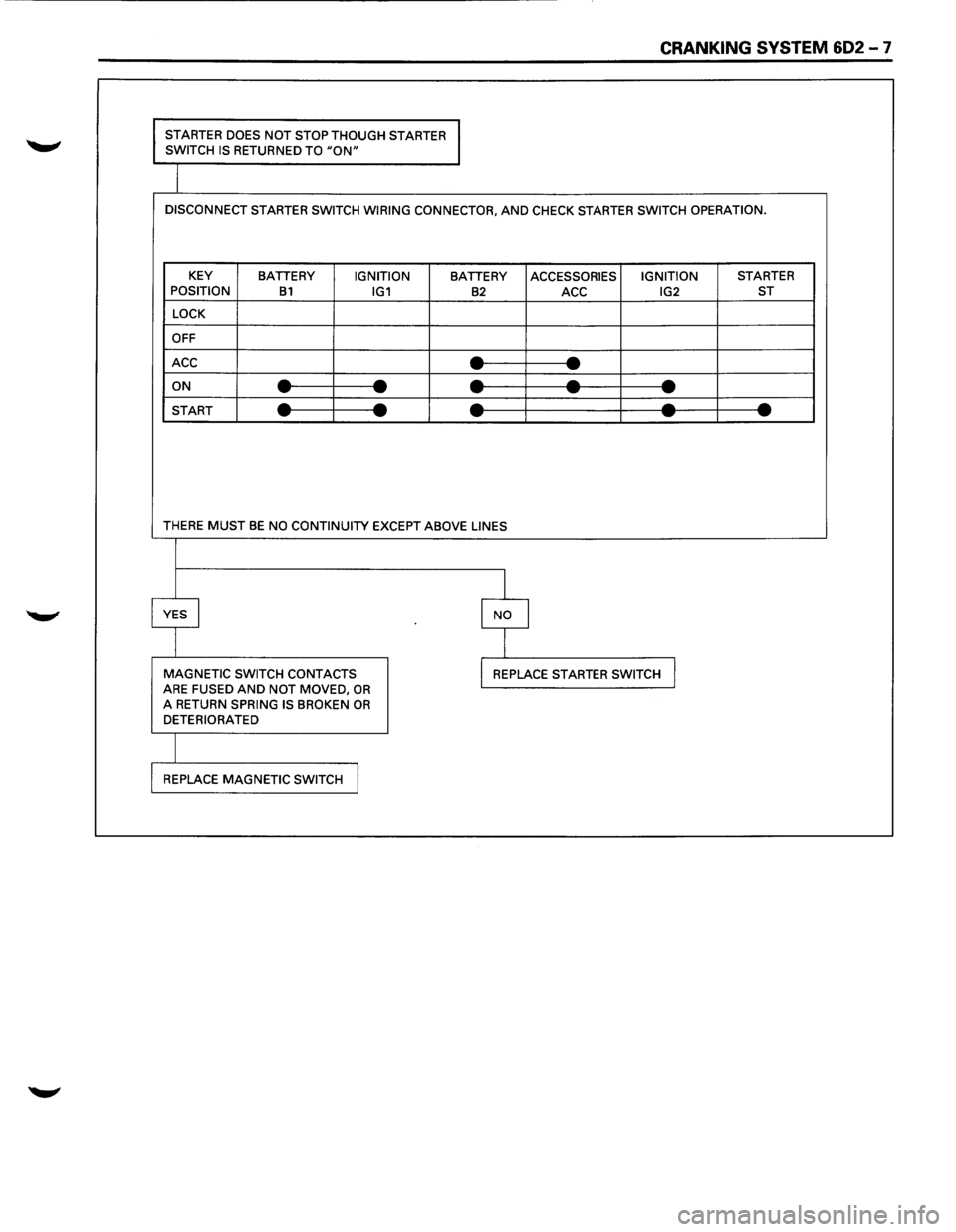
CRANKING SYSTEM 602 -7
STARTER DOES NOT STOP THOUGH STARTER
SWITCH IS RETURNED TO "ON"
DISCONNECT STARTER SWITCH WIRING CONNECTOR, AND CHECK STARTER SWITCH OPERATION.
KEY
BATTERY IGNITION BATTERY ACCESSORIES IGNITION STARTER
POSITION B1 IG1 B2 ACC IG2 ST
LOCK
OFF
ACC
--- -ON ----------START ----------
THERE MUST BE NO CONTINUITY EXCEPT ABOVE LINES
I
YES I I NO
I
MAGNETIC SWITCH CONTACTS I REPLACE STARTER SWITCH J ARE FUSED AND NOT MOVED, OR A RETURN SPRING IS BROKEN OR DETERIORATED
REPLACE
MAGNETIC SWITCH I
Page 701 of 1928
......, .., LU
READING DIAGNOSTIC TROUBLE CODES
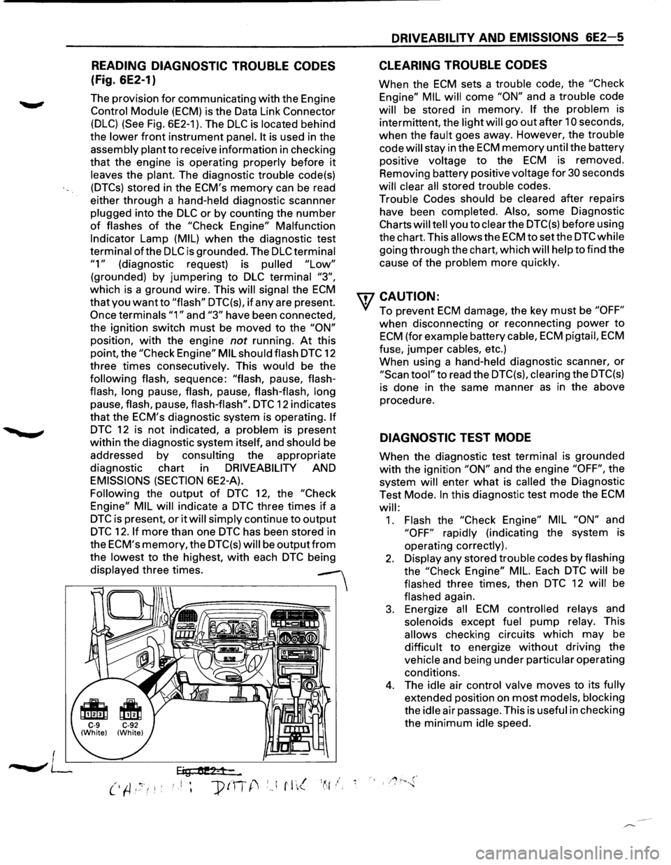
(Fig. 6E2-1)
The provision for communicating with the Engine
Control Module (ECM) is the Data Link Connector
(DLC) (See Fig. 6E2-1 ). The DLC is located behind
the
lower front instrument panel. It is used in the
assembly plant
to receive information in checking
that the engine is operating properly before it
leaves the plant. The diagnostic trouble code(s)
(DTCs) stored in the ECM's memory can be read
either through a hand-held diagnostic scannner
plugged into the
DLC or by counting the number
of flashes of the "Check Engine" Malfunction
Indicator Lamp (MIL) when the diagnostic test
terminal
ofthe DLC is grounded. The DLC terminal
"1" (diagnostic request) is pulled "Low"
(grounded) by jumpering to DLC terminal "3",
which is a ground wire. This will signal the ECM
that you want to "flash" DTC(s), if any are present.
Once terminals "1" and "3" have been connected,
the ignition switch
must be moved to the "ON"
position, with the engine not running. At this
point, the
"Check Engine" MIL should flash DTC 12
three times consecutively. This
would be the
following flash, sequence: "flash, pause, flash
flash,
long pause, flash, pause, flash-flash, long
pause, flash, pause, flash-flash". DTC 12 indicates
that the ECM's diagnostic system is operating.
If
DTC 12 is not indicated, a problem is present
within the diagnostic system itself, and should be
addressed
by consulting the appropriate
diagnostic chart in
DRIVEABILITY AND
EMISSIONS (SECTION 6E2-A).
Following the output of DTC 12, the "Check
Engine" MIL
will indicate a DTC three times if a
DTC is present, or it will simply continue to output
DTC 12. If more than one DTC has been stored in
the
ECM's memory, the DTC(s) will be outputfrom
the lowest to the highest, with each DTC being
displayed three times.
--
Eig tU!2-1-...
DRIVEABILITY AND EMISSIONS 6E2-5
CLEARING TROUBLE CODES
When the ECM sets a trouble code, the "Check
Engine" MIL
will come "ON" and a trouble code
will be stored in memory. If the problem is
intermittent, the light
will go out after 10 seconds,
when the fault goes away. However, the trouble
code
will stay in the ECM memory until the battery
positive voltage
to the ECM is removed.
Removing battery positive voltage
for 30 seconds
will clear all stored trouble codes.
Trouble
Codes should be cleared after repairs
have been completed. Also, some Diagnostic
Charts will tell you to clear the DTC(s) before using
the chart. This
allows the ECM tosetthe DTCwhile
going through the chart, which will help to find the
cause
of the problem more quickly.
wcAUTION:
• To prevent ECM damage, the key must be "OFF"
when disconnecting or reconnecting power to
ECM (for example battery cable, ECM pigtail, ECM
fuse, jumper cables, etc.)
When using a hand-held diagnostic scanner,
or
"Scan tool" to read the DTC(s), clearing the DTC(s)
is done in the same manner as in the above
procedure.
DIAGNOSTIC TEST MODE
When the diagnostic test terminal is grounded
with the ignition "ON" and the engine "OFF", the
system
will enter what is called the Diagnostic
Test Mode.
In this diagnostic test mode the ECM
will:
1. Flash the "Check Engine" MIL "ON" and
"OFF" rapidly (indicating the system is
operating correctly).
2. Display any stored trouble codes by flashing
the
"Check Engine" MIL. Each DTC will be
flashed three times, then
DTC 12 will be
flashed again.
3. Energize all ECM controlled relays and
solenoids except
fuel pump relay. This
allows checking circuits which may be
difficult to energize without driving the
vehicle and being under particular operating
conditions.
4. The idle air control valve moves to its fully
extended position on most models, blocking
the
idle air passage. This is useful in checking
the
minimum idle speed.
Page 720 of 1928
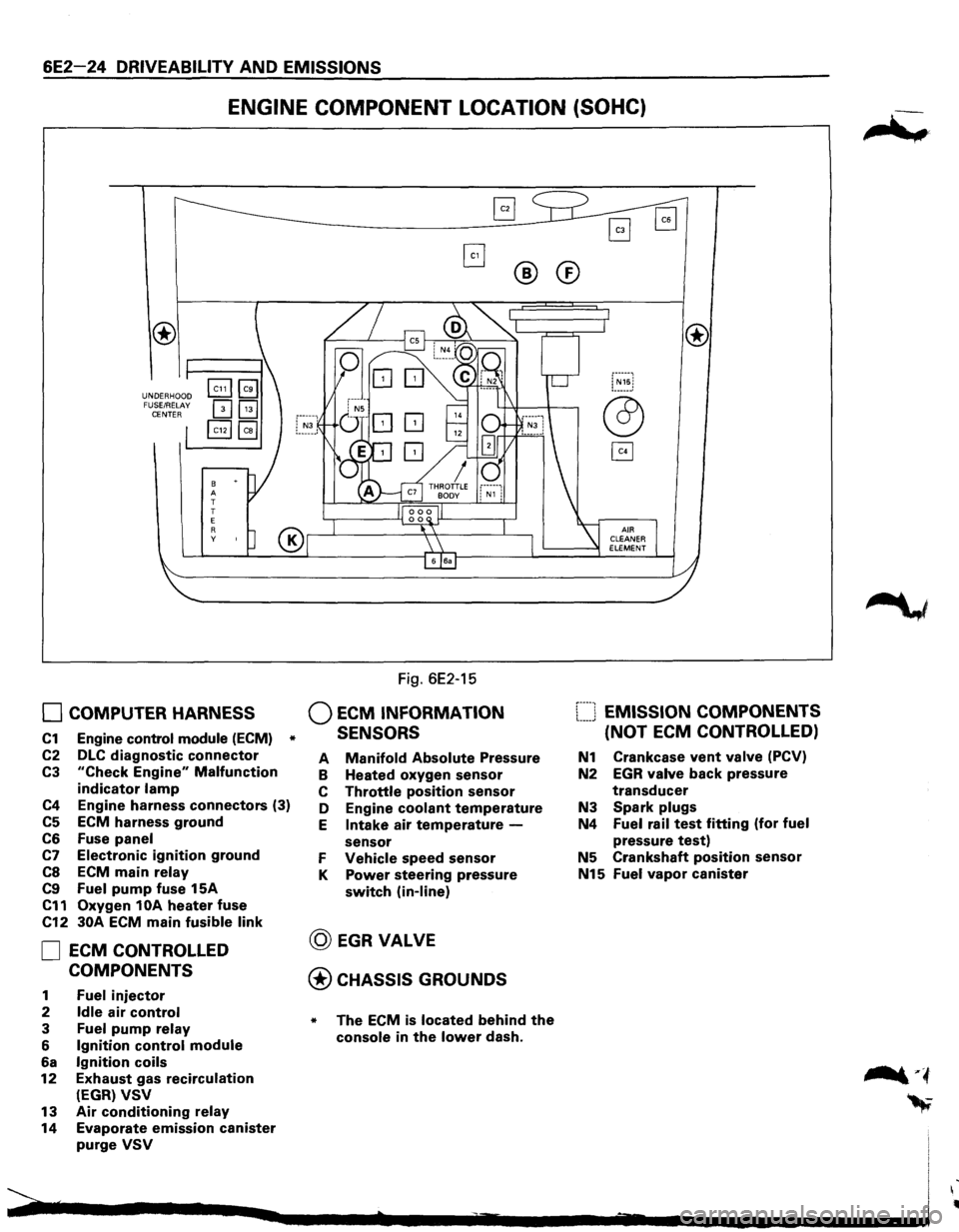
6E2-24 DRIVEABILITY AND EMISSIONS
ENGINE COMPONENT LOCATION (SOHC)
UNDERHOOD
FUSE/RELAY
CENTER
8 A
T
T
E
R y
0 COMPUTER HARNESS
C1 Engine control module (ECM) *
C2 DLC diagnostic connector
C3 "Check Engine" Malfunction
indicator lamp
C4 Engine harness connectors (3)
C5 ECM harness ground
C6 Fuse panel
C7 Electronic ignition ground
CS ECM main relay
C9 Fuel pump fuse 15A
C11 Oxygen 1 OA heater fuse
C12 30A ECM main fusible link
0 ECM CONTROLLED
COMPONENTS
1 Fuel injector
2 Idle air control
3 Fuel pump relay
6 Ignition control module
6a Ignition coils
12 Exhaust gas recirculation
(EGR) VSV
13 Air conditioning relay
14 Evaporate emission canister
purge VSV
Fig. 6E2-15
Q ECM INFORMATION
SENSORS
®
A Manifold Absolute Pressure
B Heated oxygen sensor
C Throttle position sensor
D Engine
coolant temperature
E Intake air temperature -
sensor
F Vehicle speed sensor
K Power steering pressure
switch (in-line)
@ EGRVALVE
@CHASSIS GROUNDS
* The ECM is located behind the
console in the lower dash.
®
[::::J EMISSION COMPONENTS
(NOT
ECM CONTROLLED)
N1 Crankcase vent valve (PCV)
N2 EGR valve back pressure
transducer
N3 Spark plugs
N4 Fuel rail test fitting (for fuel
pressure test)
N5 Crankshaft position sensor
N15 Fuel vapor canister
Page 721 of 1928
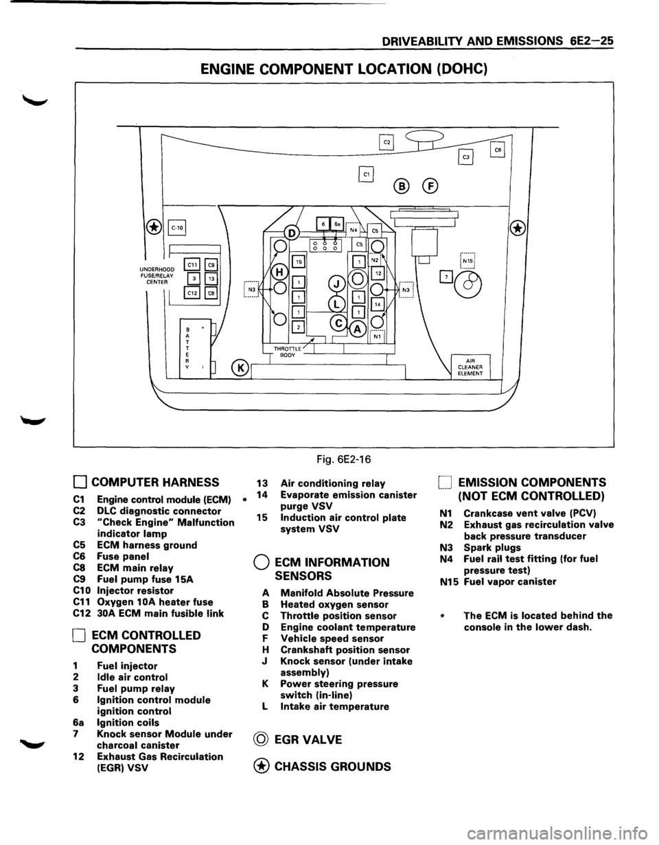
DRIVEABILITY AND EMISSIONS 6E2-25
ENGINE COMPONENT LOCATION (DOHC)
®B
UNDERHOOD FUSE/RELAY CENTER
B A T
T
E
A y
0 COMPUTER HARNESS
C1 Engine control module (ECM)
C2 DLC diagnostic connector
C3 "Check Engine" Malfunction
indicator lamp
C5 ECM harness ground
C6 Fuse panel
C8 ECM main relay
C9 Fuel pump fuse 15A
C10 Injector resistor
C11 Oxygen 1 OA heater fuse
C12
30A ECM main fusible link
0 ECM CONTROLLED
COMPONENTS
1 Fuel injector
2 Idle air control
3 Fuel pump relay
6 Ignition control module
ignition control
6a Ignition coils
7 Knock sensor Module under
charcoal canister
12
Exhaust Gas Recirculation
(EGR) VSV
*
®®
Fig. 6E2-16
13 Air conditioning relay
14 Evaporate emission canister
purge VSV
15 Induction air control plate
system VSV
Q ECM INFORMATION
SENSORS
A Manifold Absolute Pressure
B Heated oxygen sensor
c Throttle position sensor
D Engine
coolant temperature
F Vehicle speed sensor
H Crankshaft
position sensor
J Knock sensor
(under intake
assembly)
K Power steering pressure
switch (in-line)
L Intake air temperature
@ EGRVALVE
@ CHASSIS GROUNDS
f----1 EMISSION COMPONENTS !.-----' (NOT ECM CONTROLLED)
N1 Crankcase vent valve (PCV)
N2 Exhaust gas
recirculation valve
back pressure transducer
N3 Spark plugs
N4 Fuel rail test fitting (for fuel
pressure test)
N15 Fuel vapor canister
* The ECM is located behind the
console in the lower dash.
Page 722 of 1928
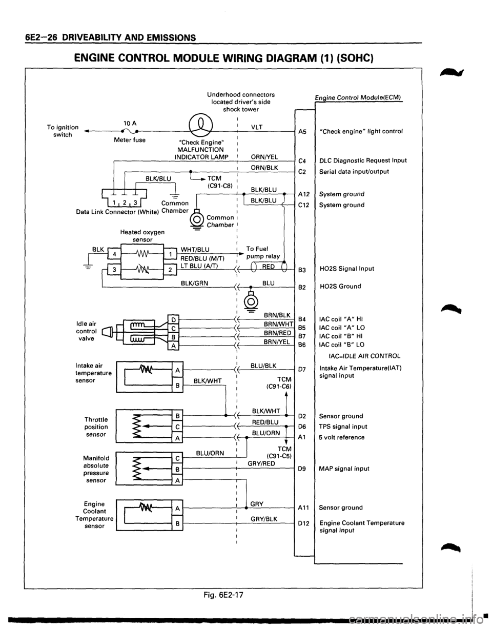
6E2-26 DRIVEABILITV AND EMISSIONS
ENGINE CONTROL MODULE WIRING DIAGRAM (1) (SOHC}
To ignition
switch 10 A
Meter fuse Underhood
connectors
located driver's side
shock tower
"Check Engine" MALFUNCTION
.-----------..:.:.1 N.:.:D:..:.IC=A~T~O:..:.R.:....=:.LA..::.M.:..::P:..___-,--___.:O:..:.R.:.:.N::.._IY.....:E:..:L=----1 c4
.------~~----~~O:..:R:..:N/~8~L=-=K--~ C 2
TCM
(C91-C8)
Engine Control Module(ECM)
"Check
engine" light control
DLC Diagnostic Request Input
Serial
data inpuVoutput
.--------f---+-....::...::;_;__=---_-1 A 12 System ground
Common
Data Link Connector (White) Chamber L.....::.=::....=..:=-=----+---1 C12 System ground
Intake air
temperature sensor
Throttle position
sensor
Manifold absolute pressure sensor
Engine
Coolant Temperature sensor Heated
oxygen
J-,.:..:W:.:..H.:..:T.:.:I8:..:L:.:U:......__ __ ....-To Fuel
RED/BLU (M/T)
1---=-'L T'-.!8~L:!:U'--l(.::::A/T!....!...!....) ---< f------lt+-~!,!..._'H---1 83
BRN/8LK
84
8RN/WHT 85
BRN/RED 87
8RN!YEL
BS
1---------~~~B~L~U~/8~L~K~--I 07
BLK/WHT
TCM
(C91-C6)
BLK/WHT 1------------4>---< t-----=~:..:.:..:_.:..:_ ....... -1 02
1-----------~ f----'-=-'-==--....-1 06
1-----------~ f--.-::..:=.=.:....=..c~-+--1 A 1
BLU/ORN
H02S Signal Input
H02S Ground
lAC coil "A" HI
lAC coil "A" LO
lAC coil "B" HI
lAC coil "B" LO
IAC=IDLE AIR CONTROL
Intake
Air Temperature(IAT)
signal input
Sensor ground
TPS signal input
5 volt reference
MAP
signal input
1---------'----...._.G:=.:..:.RY-=--------1 A 11 Sensor ground
1-------;---.:::G:..:R_;_YI:...::8:..:L::..:K:__---I 012 Engine Coolant Temperature
signal input
Fig. 6E2-17
•