oil ISUZU TROOPER 1995 Owner's Guide
[x] Cancel search | Manufacturer: ISUZU, Model Year: 1995, Model line: TROOPER, Model: ISUZU TROOPER 1995Pages: 1928
Page 147 of 1928
POWER STEERING GEAR AND PUMP 381-9
STEERING GEAR
1.,!,.1 DISASSEMBL V
W CAUTION:
UNIT REPAIR
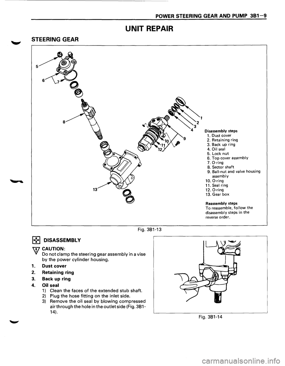
Fig. 381-13
Yf Do not clamp the steering gear assembly in a vise
by the power cylinder housing.
1. Dust cover
2. Retaining ring
3. Back up ring
4. Oil seal
1) Clean the faces of the extended stub shaft.
2) Plug the hose fitting on the inlet side.
3) Remove the oil seal by blowing compressed
air through the
hole in the outlet side (Fig. 381-
14).
Disassembly steps
1. Dust cover
2. Retaining ring
3. Back up ring
4.
Oil seal 5. Lock nut 6. Top cover assembly
7. 0-ring
8. Sector shaft
9.
Ball-nut and valve housing
assembly
10. 0-ring
11. Seal ring
12. 0-ring
13. Gear
box
Reassembly steps
To reassemble, follow the
disassembly steps in the
reverse order.
Fig. 381-14
Page 151 of 1928
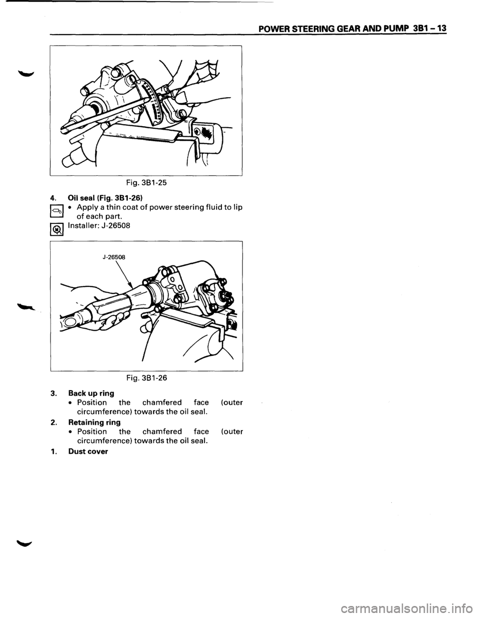
Fig. 381-25
4. Oil seal (Fig. 381-26)
~ • Apply a thin coat of power steering fluid to lip
D of each part.
l®..llnstaller: J-26508
J-26508
Fig. 381-26
3. Back up ring
• Position the chamfered face (outer
circumference) towards the oil seal.
2. Retaining ring
• Position the chamfered face (outer
circumference) towards the oil seal.
1. Dust cover
POWER STEERING GEAR AND PUMP 381 -13
Page 152 of 1928
381-14 POWER STEERING GEAR AND PUMP
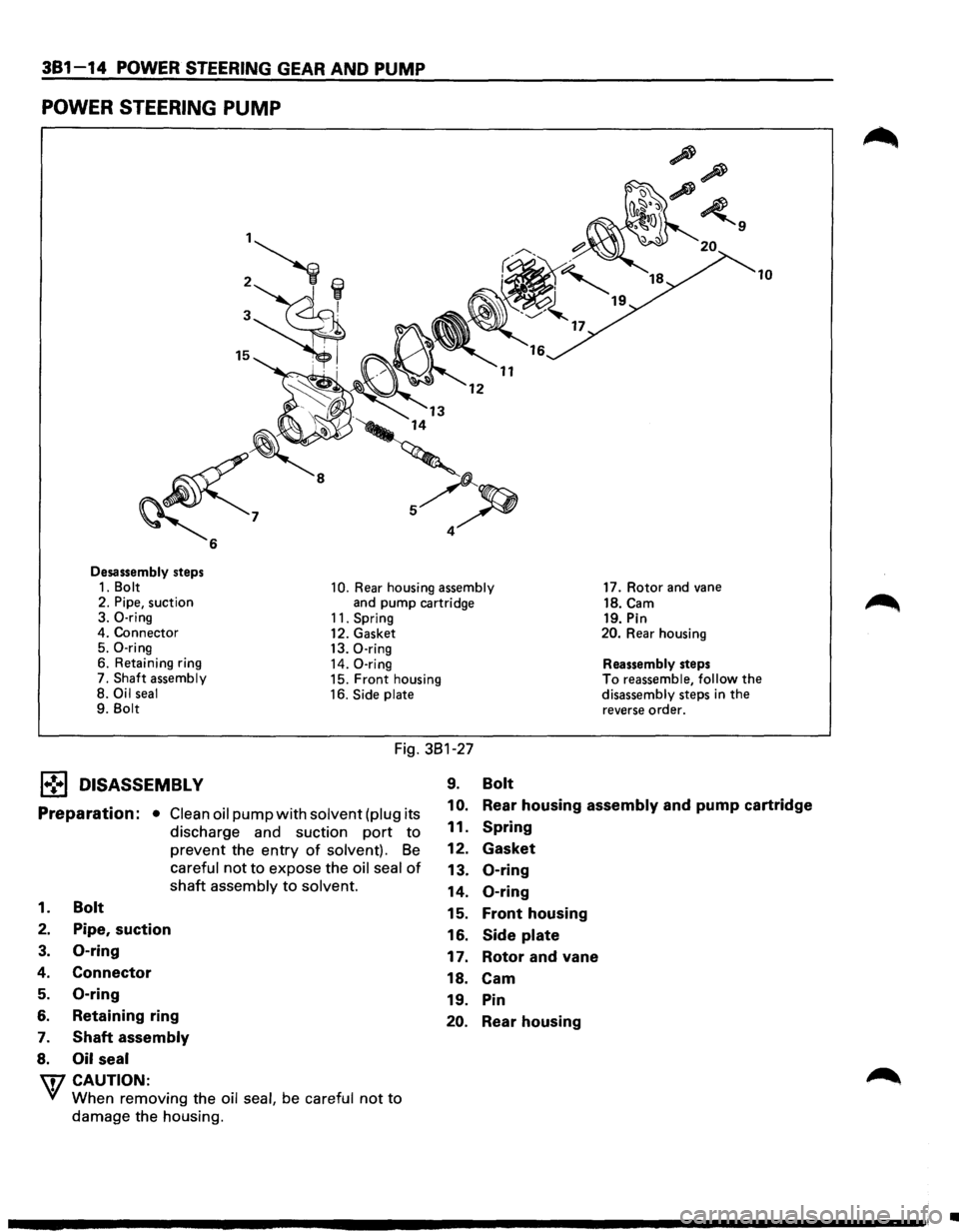
POWER STEERING PUMP
Desassembly steps 1. Bolt 10. Rear housing assembly 2. Pipe, suction
and pump cartridge
3. 0-ring 11. Spring 4. Connector
12. Gasket
5. 0-ring 13. 0-ring 6. Retaining ring
14. 0-ring 7. Shaft assembly 15. Front housing
8. Oil seal 16. Side plate 9. Bolt
Fig. 381-27
l•!•l DISASSEMBLY 9. Bolt
17. Rotor and vane
18.Cam 19. Pin 20. Rear housing
Reassembly steps
10
To reassemble, follow the disassembly steps in the
reverse order.
Preparation: • Clean oil pump with solvent (plug its
discharge and suction
port to
prevent the entry of solvent). Be
careful not to expose the oil seal of
shaft assembly to solvent.
1 0. Rear housing assembly and pump cartridge
1. Bolt
2. Pipe, suction
3. 0-ring
4. Connector
5. 0-ring
6. Retaining ring
7. Shaft assembly
8. Oil seal
'\fl CAUTION:
~ When removing the oil seal, be careful not to
damage the housing.
11. Spring
12. Gasket
13. 0-ring
14. 0-ring
15. Front housing
16. Side
plate
17. Rotor and vane
18.
Cam
19. Pin
20. Rear housing
•
Page 153 of 1928
[1!) INSPECTION AND REPAIR
Make all necessary adjustments, repairs, and part
replacements
if wear, damage, or other problems are
discovered during inspection.
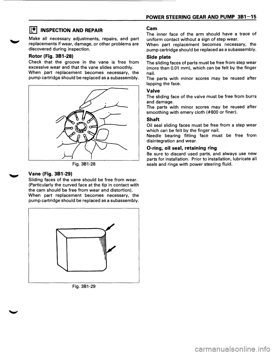
Rotor (Fig. 381-28)
Check that the groove in the vane is free from
excessive wear and that the vane slides smoothly.
When part replacement becomes necessary, the
pump cartridge
should be replaced as a subassembly.
Fig. 381-28
Vane (Fig. 381-29)
Sliding faces of the vane should be free from wear.
(Particularly the curved face at the tip in contact with
the cam should be free from wear and distortion).
When part
replacement becomes necessary, the
pump cartridge should be replaced as a subassembly.
Fig. 381-29
POWER STEERING GEAR AND PUMP 381-15
Cam
The inner face of the arm should have a trace of
uniform contact without a sign of step wear.
When part
replacement becomes necessary, the
pump cartridge should be replaced as a subassembly.
Side plate
The sliding faces of parts must be free from step wear
(more than 0.01 mm), which can be felt by the finger
nail.
The parts with minor scores may be reused after
lapping the face.
Valve
The sliding face of the valve must be free from burrs
and damage.
The parts
with minor scores may be reused after
smoothing
with emery cloth (#800 or finer).
Shaft
Oil seal sliding faces must be free from a step wear
which can be felt by the finger nail.
Needle
bearing fitting face must be free from
disintegration and wear.
0-ring, oil seal, retaining ring
Be sure to discard used parts, and always use new
parts for installation. Prior to installation, lubricate all
seals
and rings with power steering fluid.
Page 154 of 1928
381-16 POWER STEERING GEAR AND PUMP
l•!•l REASSEMBL V
20. Rear housing
19. Pin
18. Cam
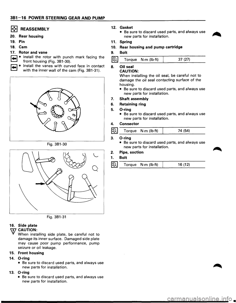
17. Rotor and vane
r=1 • Install the rotor with punch mark facing the
t=1 front housing (Fig. 3B1-30).
r=1 • Install the vanes with curved face in contact
t=1 with the inner wall of the cam (Fig. 3B1-31 ).
16. Side plate
\fl CAUTION:
Fig. 3B1-30
~
Fig. 3B1-31
"---
Q
'if When installing side plate, be careful not to
damage its inner surface. Damaged side plate
may cause poor pump performance, pump
seizure or oil leakage.
15. Front housing
14.
0-ring
• Be sure to discard used parts, and always use
new parts for installation.
13. 0-ring
• Be sure to discard used parts, and always use
new parts
for installation.
12.
11.
10.
9.
Gasket
• Be sure to discard used parts, and always use
new parts for installation.
Spring
Rear housing and pump cartridge
Bolt
l~I_T_o_rq_u_e_N_·_m_(_lb_·f_tl____. ___ 3_7_(2_7_) __ _
8.
7.
6.
5.
4.
~
3.
2.
1.
~
Oil seal
CAUTION:
When installing the oil seal, be careful not to
damage the oil seal contacting surface of the
housing.
• Be sure to discard used parts, and always use
new parts for installation.
Shaft assembly
Retaining ring
0-ring
• Be sure to discard used parts, and always use
new parts for installation.
Connector
Torque N·m (lb·ft) 74 (54)
0-ring
• Be sure to discard used parts, and always use
new parts for installation.
Pipe, suction
Bolt
Torque N·m (lb·ft) 16 (12)
..
Page 155 of 1928
POWER STEERING GEAR AND PUMP 381-17
MAIN DATA AND SPECIFICATIONS
GENERAL SPECIFICATIONS
Steering unit
Type
Gear ratio
Oil pump
Type
Operating
fluid
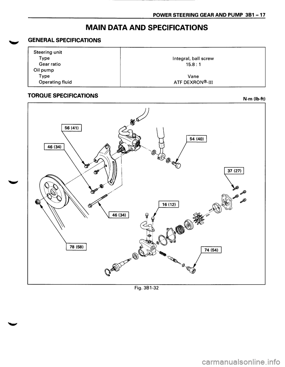
TORQUE SPECIFICATIONS
Fig. 381-32
Integral, ball screw
15.8: 1
Vane
ATF
DEXRON®-m
N·m (lb.ft)
Page 156 of 1928
381-18 POWER STEERING GEAR AND PUMP
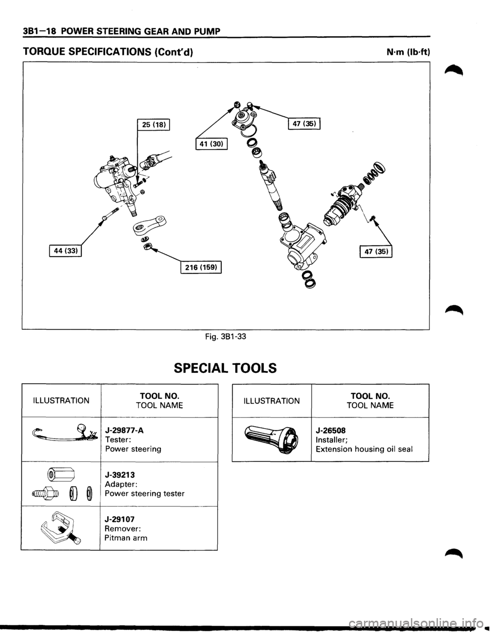
TORQUE SPECIFICATIONS (Cont'd) N·m (lb·ft)
25 (18)
Fig. 381-33
SPECIAL TOOLS
ILLUSTRATION TOOL
NO.
TOOL NAME ILLUSTRATION TOOL
NO.
TOOL NAME
~
J-29877-A
Tester: Power steering
~
J-26508
Installer;
Extension housing oil seal
~ J-39213
~ ID ®
Adapter:
Power steering tester
~
J-29107
Remover:
Pitman arm
Page 171 of 1928
FRONT SUSPENSION 3C-7
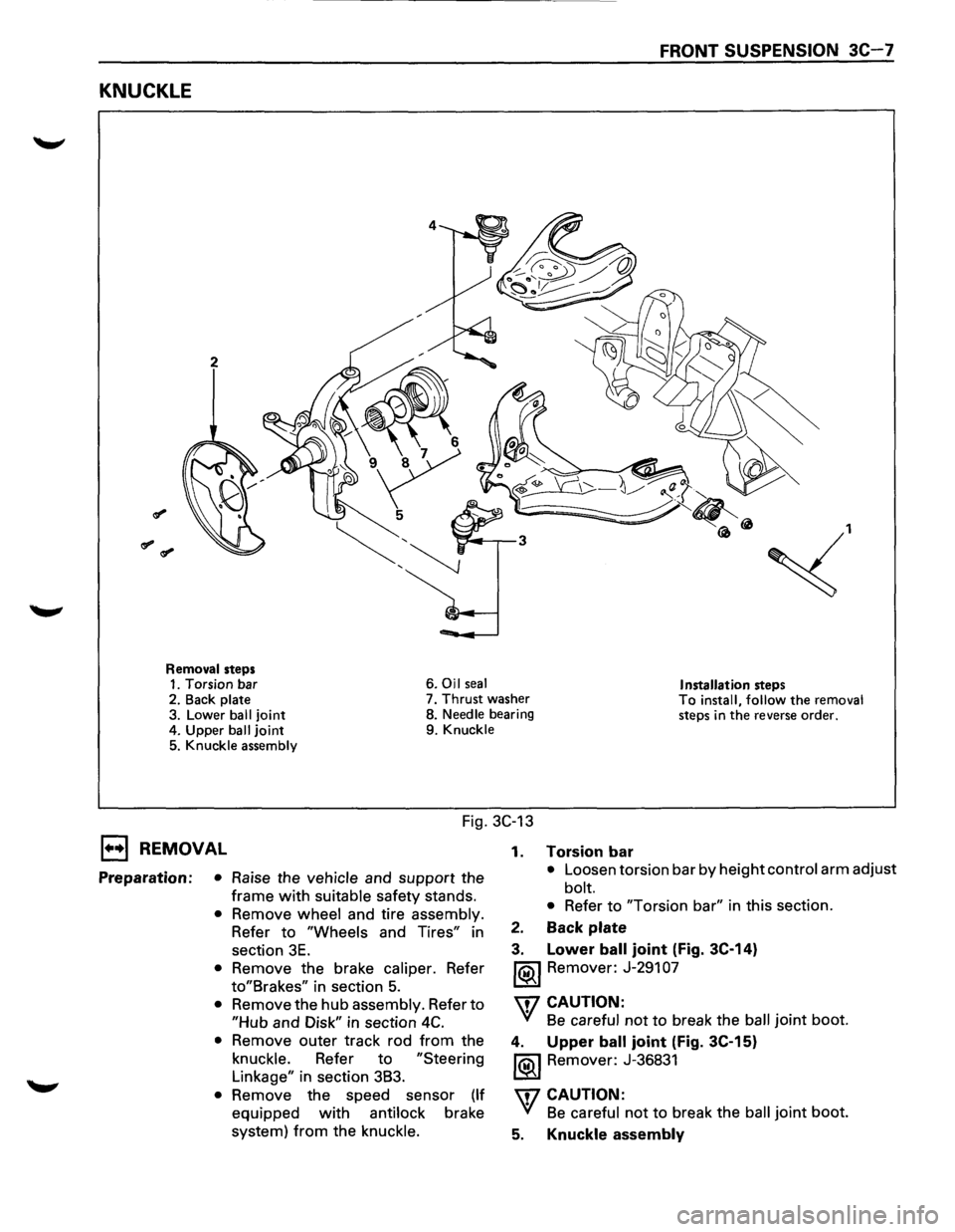
KNUCKLE
2
~,
Removal steps 1. Torsion bar 6. Oil seal Installation steps 2.
Back plate 7. Thrust washer To install, follow the removal steps in the reverse order. 3. Lower ball joint 8. Needle bearing
4. Upper
ball joint 9. Knuckle
5. Knuckle assembly
Fig. 3C-13
1••1 REMOVAL
Preparation: • Raise the vehicle and support the
frame
with suitable safety stands.
• Remove wheel and tire assembly.
Refer to
"Wheels and Tires" in
section
3E.
• Remove the brake caliper. Refer
to"Brakes" in section 5.
• Remove the hub assembly. Refer to
"Hub and Disk" in section 4C.
• Remove outer track rod from the
knuckle. Refer to
"Steering
Linkage" in section 3B3.
• Remove the speed sensor (If
equipped with antilock brake
system)
from the knuckle. 1.
Torsion bar
• Loosen
torsion bar by height control arm adjust
bolt.
• Refer to "Torsion bar" in this section.
2. Back plate
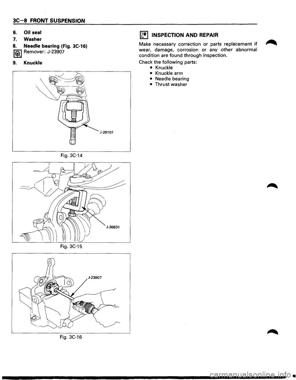
3. Lower ball joint (Fig. 3C-14)
1®.1 Remover: J-291 07
'\f7 CAUTION:
'(! Be careful not to break the ball joint boot.
4. Upper ball joint (Fig. 3C-15)
1®.1 Remover: J-36831
'\f7 CAUTION:
'(! Be careful not to break the ball joint boot.
5. Knuckle assembly
Page 172 of 1928
3C-8 FRONT SUSPENSION
6. Oil seal
7. Washer
8. Needle bearing (Fig. 3C-16)
1®.1 Remover: J-23907
9. Knuckle
Fig. 3C-14
Fig. 3C-15
Fig. 3C-16
J-29107
11!) INSPECTION AND REPAIR
Make necessary correction or parts replacement if ~
wear, damage, corrosion or any other abnormal
condition are found through inspection.
Check the
following parts:
• Knuckle
• Knuckle arm
• Needle bearing
• Thrust washer
•
Page 173 of 1928
I••IINSTALLATION
9. Knuckle
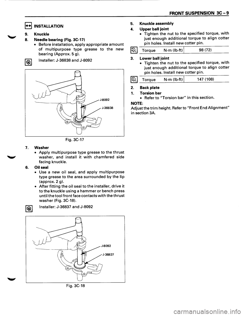
8. Needle bearing (Fig. 3C-17)
• Before installation, apply appropriate amount
of multipurpose type grease to the new
bearing (Approx. 5 g).
1®.1 Installer: J-36838 and J-8092
Fig. 3C-17
7. Washer
• Apply multipurpose type grease to the thrust
washer, and install it with chamfered side
facing
knuckle.
6. Oil seal
• Use a new oil seal, and apply multipurpose
type grease to the area surrounded by the lip
(approx. 2 g).
• After fitting the oil seal to the installer, drive it
to the knuckle using a hammer or bench press
until the tool front face contacts with the thrust
washer (Fig. 3C-18).
Installer:
J-36837 and J-8092
Fig. 3C-18
FRONT SUSPENSION 3C-9
5. Knuckle assembly
4. Upper ball joint
• Tighten the nut to the specified torque, with
just enough additional torque to align cotter
pin holes. Install new cotter pin.
~~~ Torque N·m (lb·ftl I 98 (72)
3. Lower ball joint
• Tighten the nut to the specified torque, with
just enough additional torque to align cotter
pin holes. Install new cotter pin.
~~~ Torque N·m (lb·ftl I 147 (108)
2. Back plate
1. Torsion bar
• Refer to "Torsion bar" in this section.
NOTE:
Adjust the trim height. Refer to "Front End Alignment"
in section 3A.