oil ISUZU TROOPER 1995 Repair Manual
[x] Cancel search | Manufacturer: ISUZU, Model Year: 1995, Model line: TROOPER, Model: ISUZU TROOPER 1995Pages: 1928
Page 250 of 1928
48 - 8 REAR AXLE
6. Nut
• Remove the bearing holder mounting nuts.
7. Axle shaft assembly
NOTE:
• Be sure not to damage the oil seal.
8. Snap ring
9. Retainer
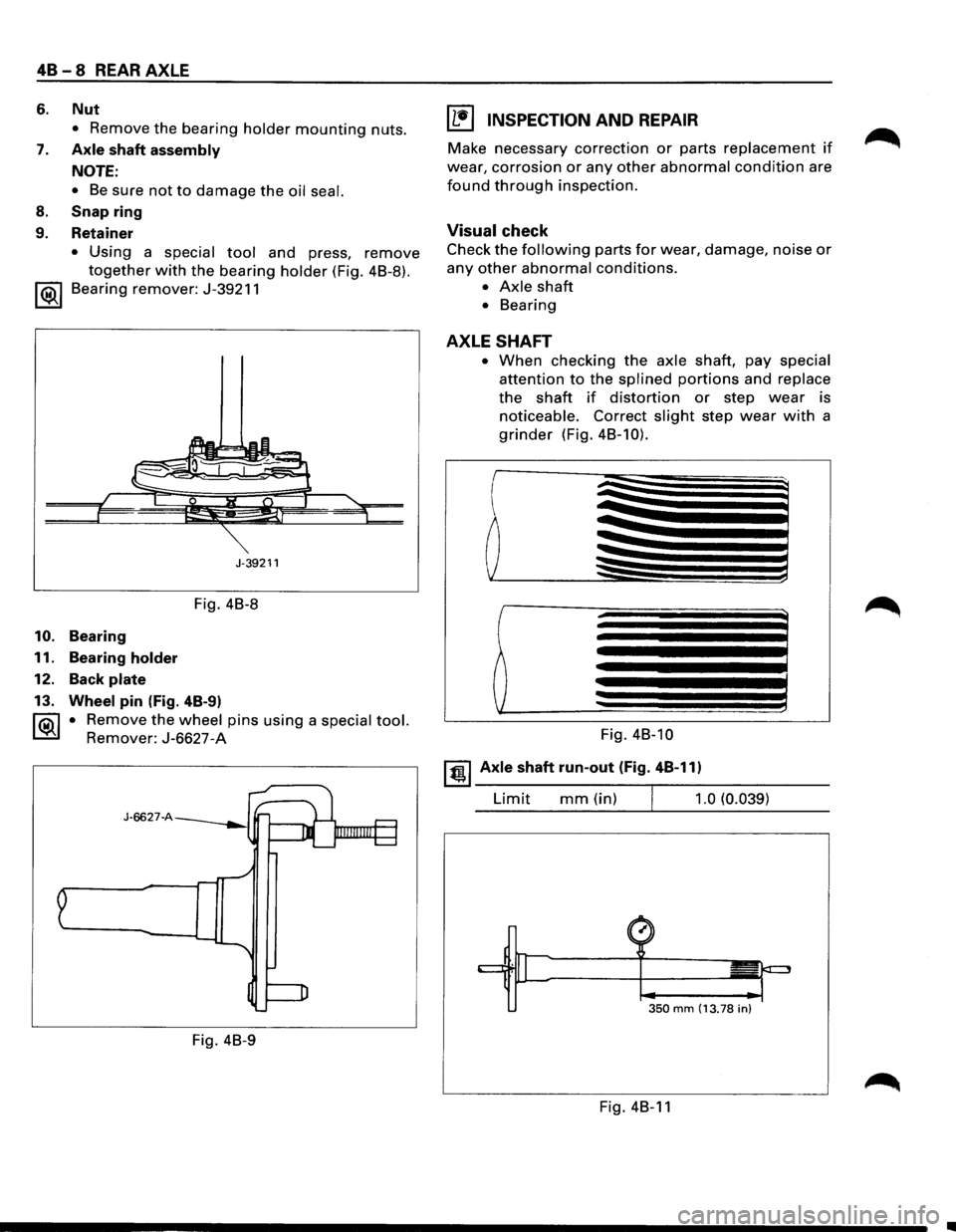
• Using a special tool and press, remove
together with the bearing holder (Fig. 4B-8).
1 ®I Bearing remover: J-39211
J-39211
Fig. 4B-8
10. Bearing
11. Bearing
holder
12. Back plate
13. Wheel pin (Fig. 4B-9)
1®.1 • Remove the wheel pins using a special tool.
Remover: J-6627-A
J-6627-A
Fig. 4B-9
I L•l INSPECTION AND REPAIR
Make necessary correction or parts replacement if
wear, corrosion or any other abnormal condition are
found through inspection.
Visual check
Check the following parts for wear, damage, noise or
any other abnormal conditions.
• Axle shaft
• Bearing
AXLE SHAFT
• When checking the axle shaft, pay special
attention to the splined portions and replace
the shaft if distortion or step wear is
noticeable. Correct slight step wear with a
grinder (Fig. 4B-10).
Fig. 4B-10
~~~ Axle shaft run-out (Fig. 4B-11)
Limit mm(in) 1.0 (0.039)
350 mm (13.78 in)
Fig. 4B-11
•
Page 251 of 1928
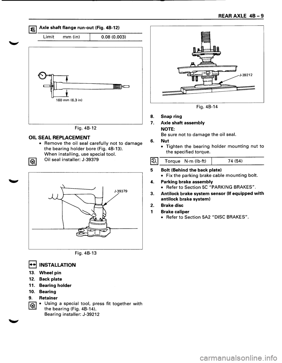
1 t!!.l Axle shaft flange run-out (Fig. 4B-12)
Limit mm (in) I 0.08 (0.003)
160 mm (6.3 in)
Fig. 4B-12
OIL SEAL REPLACEMENT
• Remove the oil seal carefully not to damage
the bearing holder bore (Fig. 4B-13).
When installing, use special tool.
1®1 Oil seal installer: J-39379
Fig. 4B-13
I••IINSTALLATION
13. Wheel pin
12. Back plate
11. Bearing holder
10. Bearing
9. Retainer
J-39379
1 ®I • Using a special tool, press fit together with
the bearing (Fig. 4B-14).
Bearing
installer: J-39212
8.
7.
6.
Fig. 4B-14
Snap ring
Axle shaft assembly
NOTE:
REAR AXLE 48-9
39212
Be sure not to damage the oil seal.
Nut
• Tighten the bearing holder mounting nut to
the specified torque.
I~I ___ T_o_rq_u_e __ N_·_m_(_lb_·f_t)~l _____ 7_4_(~5~4) ____ ___
5
4.
3.
2.
1
Bolt (Behind the back plate)
• Fix the parking brake cable mounting bolt.
Parking brake assembly
• Refer to Section 5C "PARKING BRAKES".
Antilock brake system sensor (If equipped with
antilock brake system)
Brake disc
Brake caliper
• Refer to Section 5A2 "DISC BRAKES".
Page 252 of 1928
48-1 0 REAR AXLE
PINION OIL SEAL
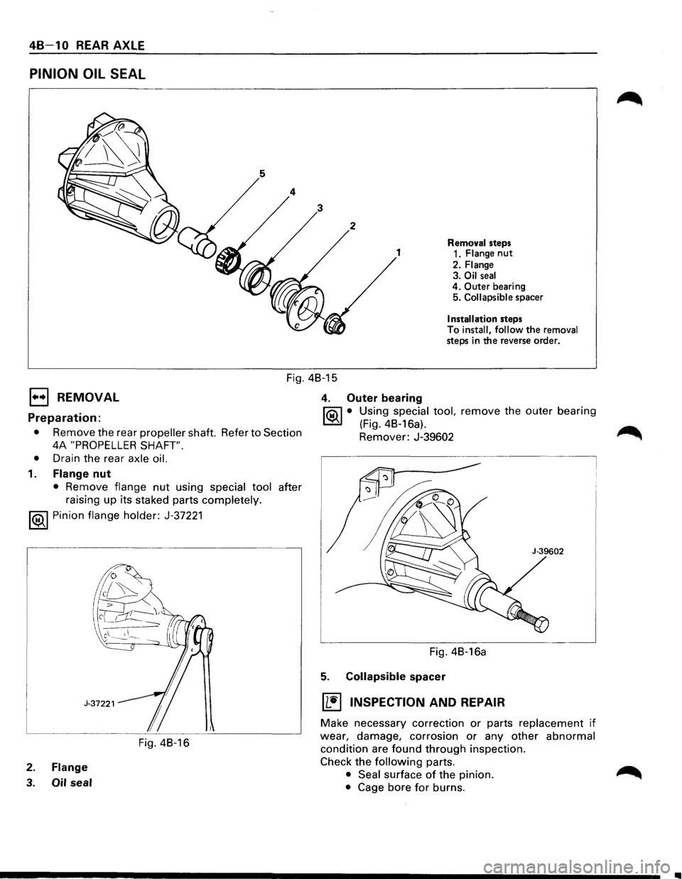
Removal steps
1 1. Flange nut
2. Flange 3. Oil seal 4. Outer bearing
5. Collapsible spacer
Installation steps
To
install, follow the removal steps in the reverse order.
Fig. 48-15
1••1 REMOVAL 4. Outer bearing
~ • Using special tool, remove the outer bearing Preparation: ~ (Fig. 48-16a).
• Remove the rear propeller shaft. Refer to Section Remover: J-39602 ~
4A "PROPELLER SHAFT".
•
Drain the rear axle oil.
1. Flange nut
• Remove flange nut using special tool after
raising up its staked parts
completely.
1®..1 Pinion flange holder: J-37221
Fig. 48-16
2. Flange
3. Oil seal
Fig. 4B-16a
5. Collapsible spacer
IL~I INSPECTION AND REPAIR
Make necessary correction or parts replacement if
wear, damage, corrosion or any other abnormal
condition are found through inspection.
Check
the following parts.
• Seal surface of the pinion.
• Cage bore for burns.
..
Page 253 of 1928
E) INSTALLATION
5. Collapsible spacer
• Discard the used collapsible spacer and install
a new one.
4. Outer bearing
NOTE:
• Do not drive in, but just temporarily set in the
outer bearing
by hand, which should be
indirectly pressed in finally by tightening the
flange nut.
3. Oil seal
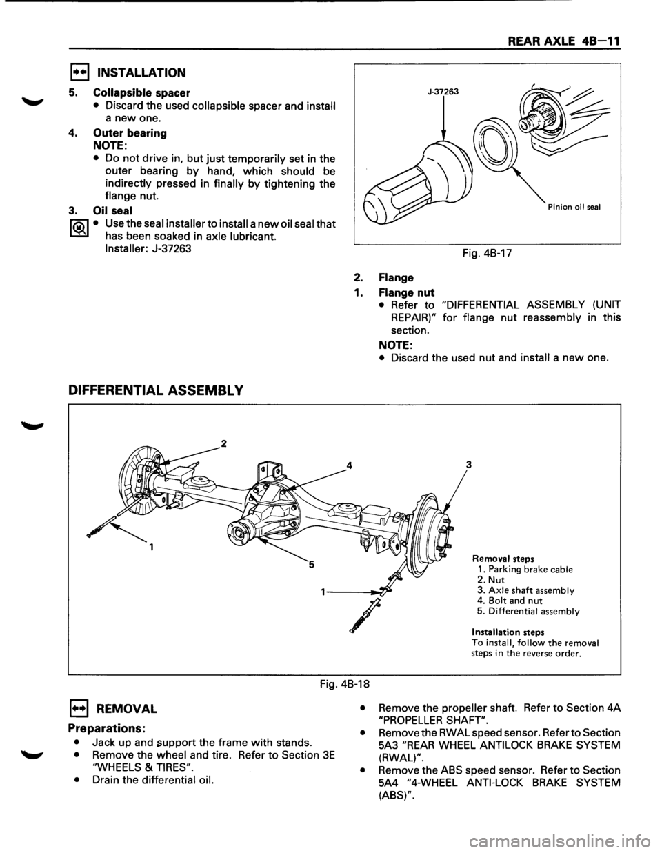
1"?.:\1 • Use the seal installer to install a new oil seal that
l.::::'i:il has been soaked in axle lubricant.
Installer:
J-37263
DIFFERENTIAL ASSEMBL V
~ 1
REAR AXLE 48-11
J-37263
Pinion oil seal
Fig. 4B-17
2. Flange
1. Flange nut
• Refer to "DIFFERENTIAL ASSEMBLY (UNIT
REPAIR)" for flange nut reassembly in this
section.
NOTE:
• Discard the used nut and install a new one.
3
/
Removal steps
1. Parking brake cable
2. Nut 3. Axle shaft assembly 4. Bolt and nut 5. Differential assembly
Installation
steps
To install, follow the removal steps in the reverse order.
Fig. 4B-18
E) REMOVAL
Preparations:
• Jack up and .support the frame with stands.
• Remove the wheel and tire. Refer to Section 3E
"WHEELS & TIRES".
•
Drain the differential oil. •
Remove
the propeller shaft. Refer to Section 4A
"PROPELLER SHAFT".
•
Remove the RWAL speed sensor. Refer to Section
5A3
"REAR WHEEL ANTILOCK BRAKE SYSTEM
(RWAL)".
•
Remove the ABS speed sensor. Refer to Section
5A4
"4-WHEEL ANTI-LOCK BRAKE SYSTEM
(ABS)".
Page 254 of 1928
48-12 REAR AXLE
1. Parking brake cable
• Remove the parking brake cable fastening clip
and disconnect the equalizer section. Refer
to
Section SC "PARKING BRAKES".
2. Nut
• Remove the bearing holder fixing nuts.
3. Axle shaft assembly
• Be sure notto damage the oil seal by axle shaft.
4.
Bolt and nut
• Remove differential carrier mounting bolts and
nuts.
5. Differential assembly
1••1 INSTALLATION
5. Differential assembly
• Clean the contact surfaces of the axle and
differential carrier.
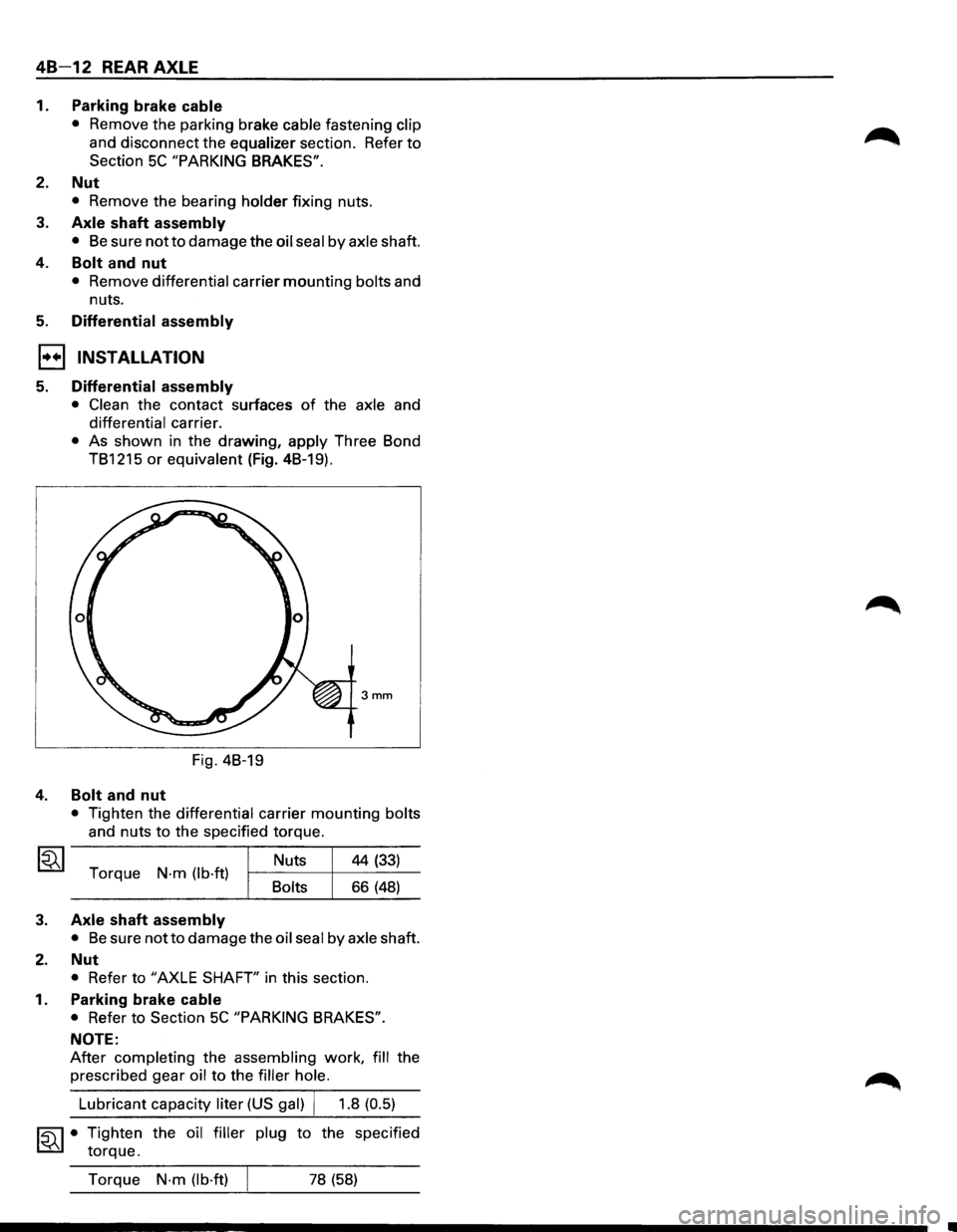
• As shown in the drawing, apply Three Bond
TB1215
or equivalent (Fig. 4B-19).
3mm
Fig. 4B-19
4. Bolt and nut
• Tighten the differential carrier mounting bolts
and nuts
to the specified torque.
Torque
N·m (lb·ft) Bolts Nuts
44
(33)
66 (48)
3. Axle shaft assembly
• Be sure notto damage
the oil seal by axle shaft.
2. Nut
• Refer to "AXLE SHAFT' in this section.
1. Parking brake cable
• Refer to Section 5C "PARKING BRAKES".
NOTE:
After completing the assembling work, fill the
prescribed gear
oil to the filler hole.
~·
Lubricant capacity liter (US gal) j 1.8 (0.5)
Tighten the oil filler plug to the specified
torque.
Torque
N·m (lb·ft) 78 (58)
Page 255 of 1928
UNIT REPAIR
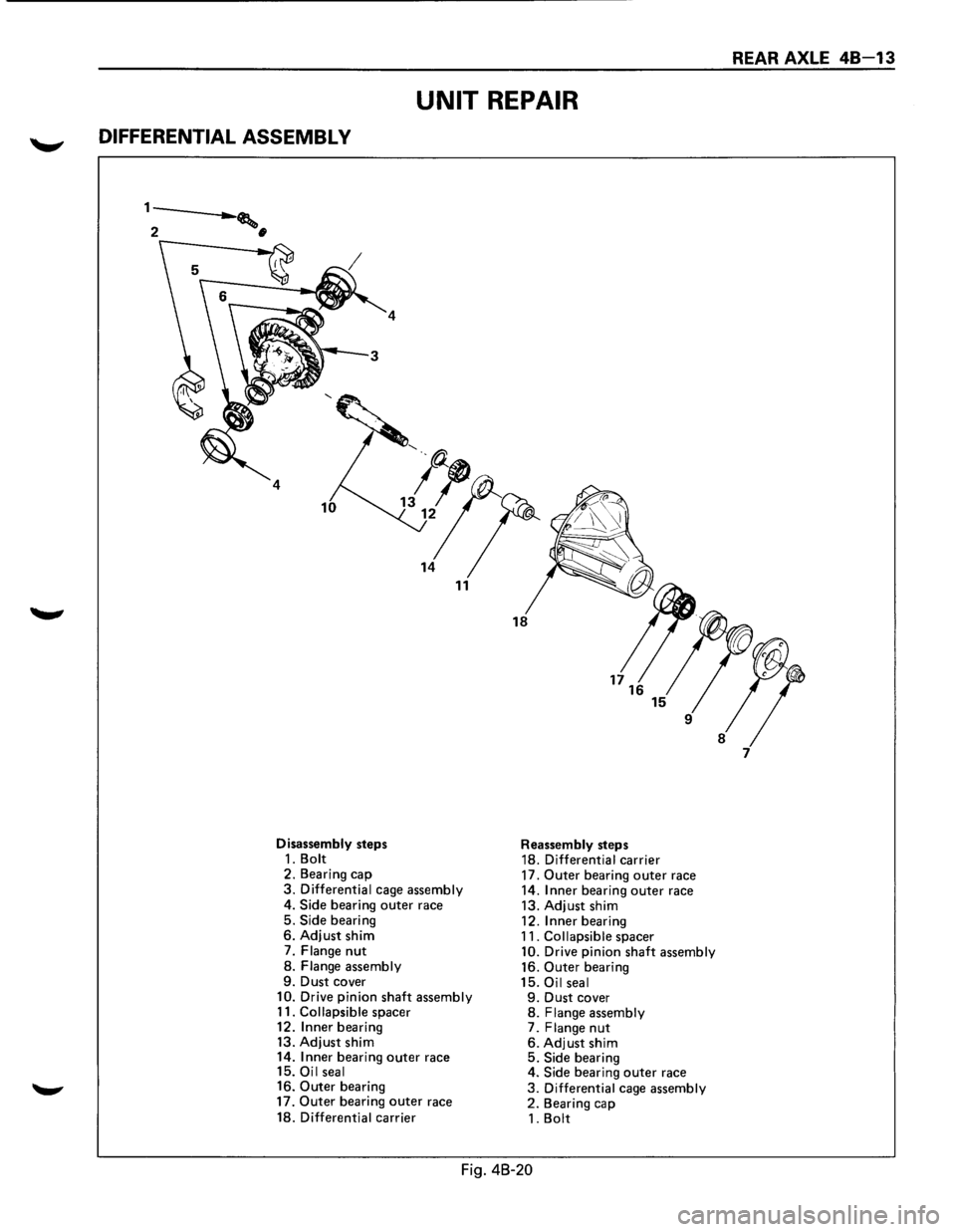
DIFFERENTIAL ASSEMBL V
1---.___. .......... ,
2 •
4
Disassembly steps 1. Bolt 2. Bearing cap 3. Differential cage assembly
4.
Side bearing outer race
5. Side bearing 6. Adjust shim
7. Flange nut
8. Flange assembly 9. Dust cover 10. Drive pinion shaft assembly
11. Collapsible spacer
12.
Inner bearing
13. Adjust shim
14. Inner bearing outer race
15. Oil seal
16. Outer bearing
17. Outer bearing outer race
18. Differential carrier
Reassembly steps
18. Differential carrier
17.
Outer bearing outer race
14. Inner bearing outer race
13. Adjust shim
12.
Inner bearing
11. Collapsible spacer 10. Drive pinion shaft assembly
16. Outer bearing
15. Oil seal 9. Dust cover 8. Flange assembly 7. Flange nut 6. Adjust shim 5. Side bearing
4. Side bearing outer race
3. Differential cage assembly 2. Bearing cap
1. Bolt
Fig. 48-20
REAR AXLE 48-13
Page 257 of 1928
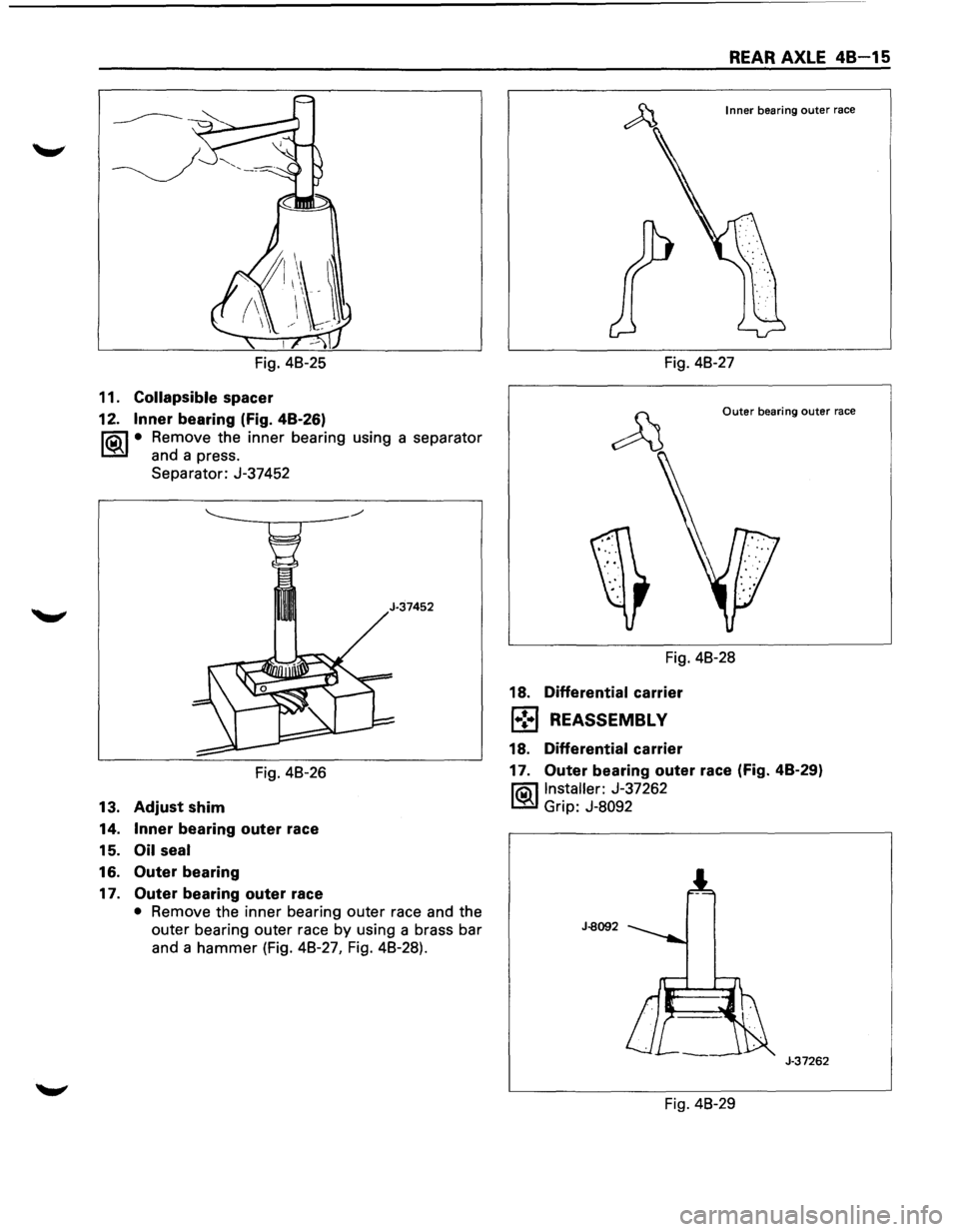
Fig. 48-25
11.
Collapsible spacer
12. Inner bearing (Fig. 48-26)
l?.iil • Remove the inner bearing using a separator
~ and a press.
Separator: J-37452
Fig. 48-26
13.
Adjust shim
14. Inner bearing outer race
15.
Oil seal
16. Outer bearing
17. Outer bearing outer race
• Remove the inner bearing outer race and the
outer bearing outer race by using a brass bar
and a
hammer (Fig. 48-27, Fig. 48-28).
REAR AXLE 48-15
Inner bearing outer race
Fig. 48-27
Outer bearing outer race
Fig. 48-28
18.
Differential carrier
1•:-1 REASSEMBL V
18. Differential carrier
17. Outer bearing outer race (Fig. 48-29)
l?.iil Installer: J-37262
~ Grip: J-8092
J-8092
J-37262
Fig. 48-29
Page 258 of 1928
48 -16 REAR AXLE
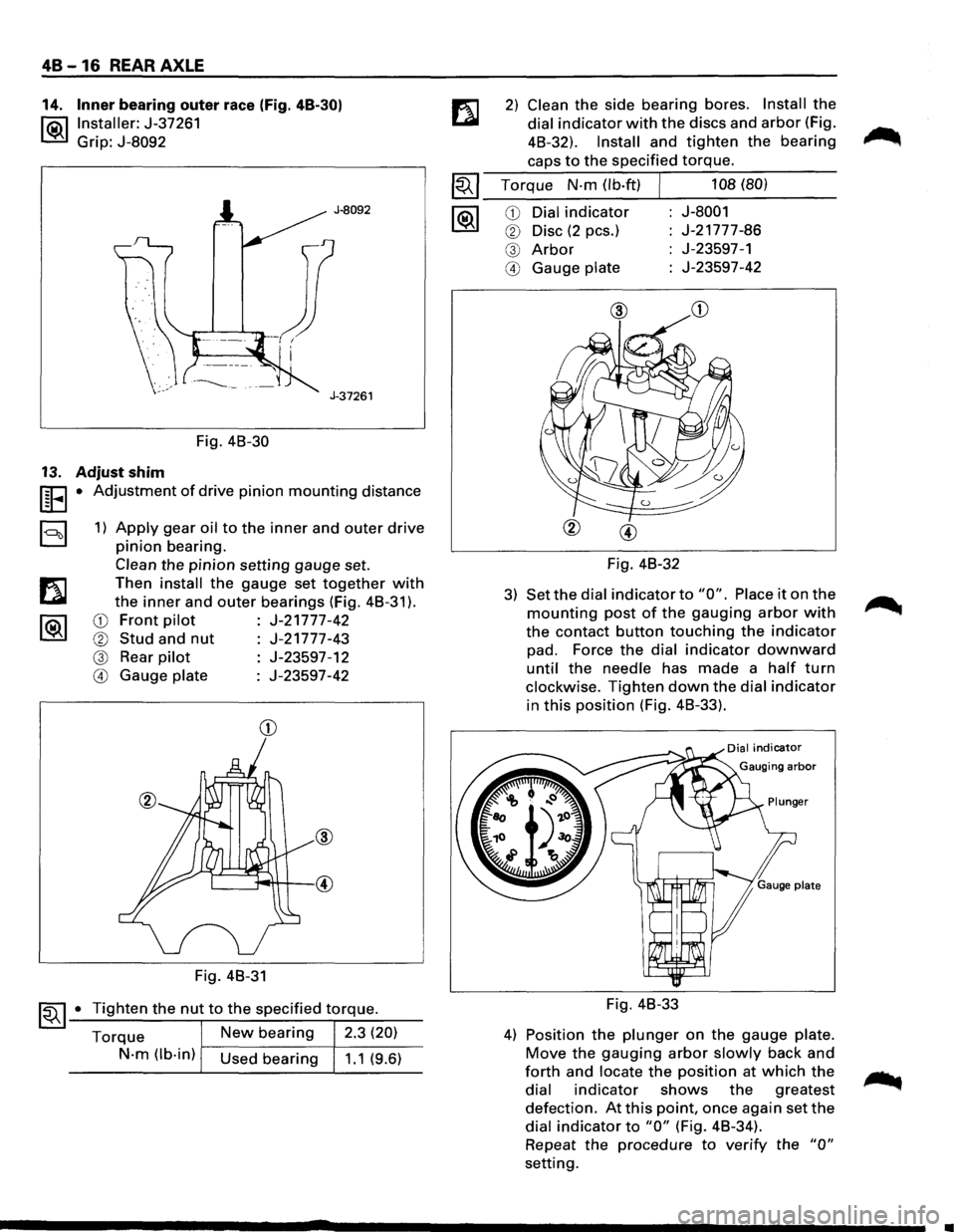
14. Inner bearing outer race (Fig. 48-30)
l®.llnstaller: J-37261
Grip: J-8092
J-8092
J-37261
Fig. 48-30
13. Adjust shim
UEI • Adjustment of drive pinion mounting distance
a 1) Apply gear oil to the inner and outer drive
pinion bearing.
Clean the pinion setting gauge set.
Then
install the gauge set together with
the inner and outer bearings (Fig. 48-31 ).
CD Front pilot J-21777-42
® Stud and nut J-21777-43
@ Rear pilot J-23597-12
@ Gauge plate J-23597-42
CD
Fig. 48-31
~~ 1-•-T_i..::..g_h_te_n_t_h_e_n_u...,t_t_o_t_h_e_s..:..p_e_c_if_ie_d_t-\
.-o_rq....:..._ue_. __
Torque New bearing 2.3 (20)
N-m (lb-in) Used bearing 1.1 (9.6)
2) Clean the side bearing bores. Install the
dial indicator with the discs and arbor (Fig.
48-32).
Install and tighten the bearing
caps to the specified torque.
~~~ Torque N-m (lb·ft) J 108 (80)
--------~----------1®.1 CD Dial indicator J-8001
® Disc (2 pes.) J-21777-86
@ Arbor J-23597-1
@ Gauge plate J-23597-42
Fig. 48-32
3) Set the dial indicator to "0". Place it on the
mounting post of the gauging arbor with
the contact button touching the indicator
pad. Force the dial indicator downward
until the needle has made a half turn
clockwise. Tighten down the dial indicator
in this position (Fig. 48-33).
Fig. 48-33
4) Position the plunger on the gauge plate.
Move the gauging arbor slowly back and
forth and locate the position at which the
dial indicator shows the greatest
defection. At this point, once again set the
dial indicator to "0" (Fig. 48-34).
Repeat
the procedure to verify the "0"
setting.
•
Page 260 of 1928
48-18 REAR AXLE
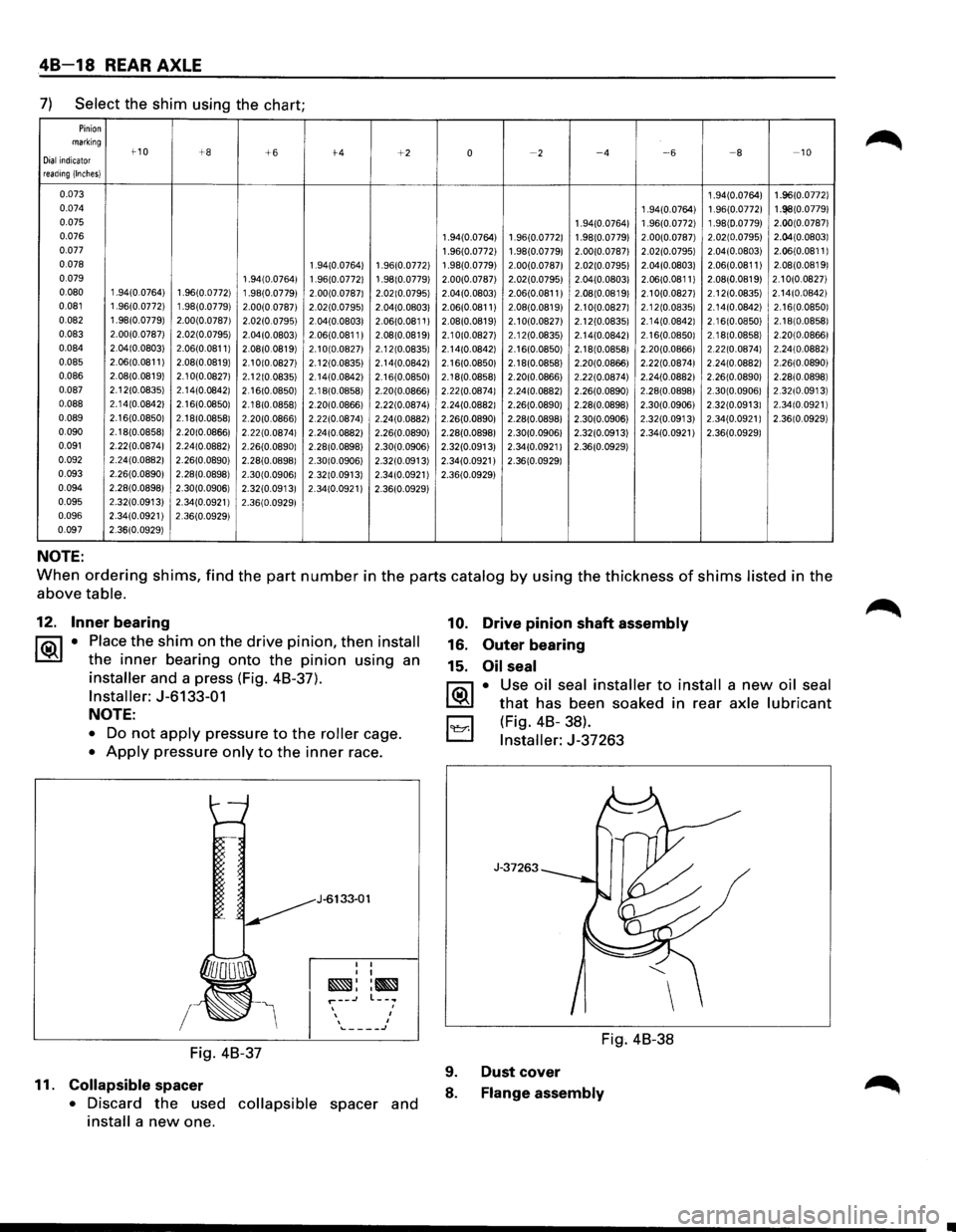
7) Select the shim using the chart;
Pinion marking t-10 +8 Dial indicator +6 t-4 +2 0 ~2 ~4 ~6 ~a -10
reading (Inches}
0.073 1 .94(0.0764} 1 .96(0.0772}
0.074 1 .94(0.0764} 1 .96(0.0772} 1.!~8(0.0779} 0.075 1 .94(0.0764} 1 .96(0.0772) 1 .98(0.0779) 2.00(0.0787}
0.076 1 .94(0.0764) 1 .96(0.0772) 1 .98(0.0779} 2.00(0.0787) 2.02(0.0795)
2.04(0.08031
0.077 1 .96(0.0772) 1 .98(0.07791 2.00(0.07871 2.02(0.07951 2.04(0.0803)
2.06(0.0811 I
0.078 1 .94(0.0764) 1 .96(0.0772) 1 .98(0.0779) 2.00(0.07871 2.02(0.07951 2.04(0.0803} 2.06(0.0811)
2.08(0.08191
0.079 1 .94(0.0764} 1 .96(0.0772} 1 .98(0.0779) 2.00(0.0787) 2.02(0.0795) 2.04(0.0803} 2.06(0.0811 I 2.08(0.0819) 2.1 0(0.0827)
0.080 1 .94(0.0764) 1 .96(0.0772} 1 .98(0.0779) 2.00(0.07871 2.02(0.07951 2.04(0.0803)
2.06(0.0811 I 2.08(0.08191 2.10(0.08271 2. 12(0.0835) 2.14(0.08421
0.081 1 .96(0.0772} 1 .98(0.0779} 2.00(0 07871 2.02(0.07951 2.04(0.08031 2.06(0.0811 I 2.08(0.08191 2.1 0(0.08271 2. 12(0.08351 2. 14(0.08421 2. 16(0.08501
0.082 1 .98(0.0779) 2.00(0.07871 2.02(0.07951 2.04(0.08031 2.06(0.0811 I
2.08(0.08191 2.1 0(0.08271 2. 12(0.08351 2. 14(0.0842} 2.16(0.08501 2. 18(0.08581
0.083 2.00(0.07871
2.02(0.07951 2.04(0.0803}
2.06(0.0811 I 2.08(0.08191 2.1 0(0.0827} 2. 12(0.0835} 2. 14(0.0842} 2. 16(0.08501 2.18(0.0858}
2.20(0.0866}
0.084 2.04(0.08031 2.06(0.0811 I
2.08(0.0819} 2.1 0(0.08271 2. 12(0.08351 2.14(0.0842} 2. 16(0.0850) 2. 18(0.08581 2.20(0.0866}
2.22(0.08741 2.24(0.08821
0.085 2.06(0.0811} 2.08(0.0819} 2.1 0(0.0827} 2. 12(0.08351 2. 14(0.0842}
2.16(0.08501 2. 18(0.0858} 2.20(0.0866} 2.22(0.0874} 2.24(0.0882} 2.26(0.0890}
0.086 2.08(0.0819} 2.1 0(0.0827} 2. 12(0.0835} 2.14(0.0842} 2.16(0.0850} 2.18(0.0858} 2.20(0.0866)
2.22(0.0874) 2.24(0.0882)
2.26(0.0890} 2.28(0.0898)
0.087 2. 12(0.0835) 2.14(0.0842) 2.16(0.08501 2. 18(0.0858) 2.20(0.0866) 2.22(0.0874) 2.24(0.0882) 2.26(0.0890) 2.28(0.08981 2.30(0.09061 2.32(0.0913)
0.088 2. 14(0.0842} 2.16(0.0850)
2.18(0.0858} 2.20(0.0866) 2.22(0.0874)
2.24(0.08821 2.26(0.0890)
2.28(0.0898) 2.30(0.0906) 2.32(0.09131 2.34(0.0921 I
0.089 2. 16(0.08501 2.18(0.08581
2.20(0.08661 2.22(0.0874)
2.24(0.0882) 2.26(0.0890) 2.28(0.0898) 2.30(0.0906) 2.32(0.0913) 2.34(0.0921)
2.36(0.0929)
0.090 2.18(0.0858) 2.20(0.0866)
2.22(0.08741 2.24(0.0882) 2.26(0.0890) 2.28(0.0898)
2.30(0.09061 2.32(0.0913)
2.34(0.0921) 2.36(0.0929)
0.091 2.22(0.0874)
2.24(0.0882)
2.26(0.08901 2.28(0.0898) 2.30(0.0906) 2.32(0.0913)
2.34(0.09211 2.36(0.0929)
0.092 2.24(0.0882) 2.26(0.0890)
2.28(0.08981 2.30(0.0906) 2.32(0.0913) 2.34(0.0921) 2.36(0.0929)
0.093 2.26(0.0890)
2.28(0.0898)
2.30(0.09061 2.32(0.0913) 2.34(0.0921) 2.36(0.0929)
0.094 2.28(0.08981 2.30(0.0906)
2.32(0.0913)
2.34(0.0921) 2.36(0.0929)
0.095 2.32(0.0913)
2.34(0.0921)
2.36(0.09291
0.096 2.34(0.0921)
2.36(0.0929)
0.097 2.36(0.0929)
NOTE:
When ordering shims, find the part number in the parts catalog by using the thickness of shims listed in the
above
table.
12. Inner bearing
1®.1 • Place the shim on the drive pinion, then install
the inner bearing onto the pinion using an
installer and a press (Fig. 48-37).
Installer: J-6133-01
NOTE:
• Do not apply pressure to the roller cage.
• Apply pressure only to the inner race.
I
Fig. 48-37
11.
Collapsible spacer
J-6133-01
I I I I
~::~ r--~ l--.. ' , , .._ ____ J
• Discard the used collapsible spacer and
install a new one.
10. Drive pinion shaft assembly
16. Outer bearing
15.
Oil seal
~·
B
Use oil seal installer to install a new oil seal
that has been soaked in rear axle lubricant
(Fig.
48-38).
Installer: J-37263
J-37263
Fig. 48-38
9.
8. Dust
cover Flange assembly
Page 266 of 1928
48-24 REAR AXLE
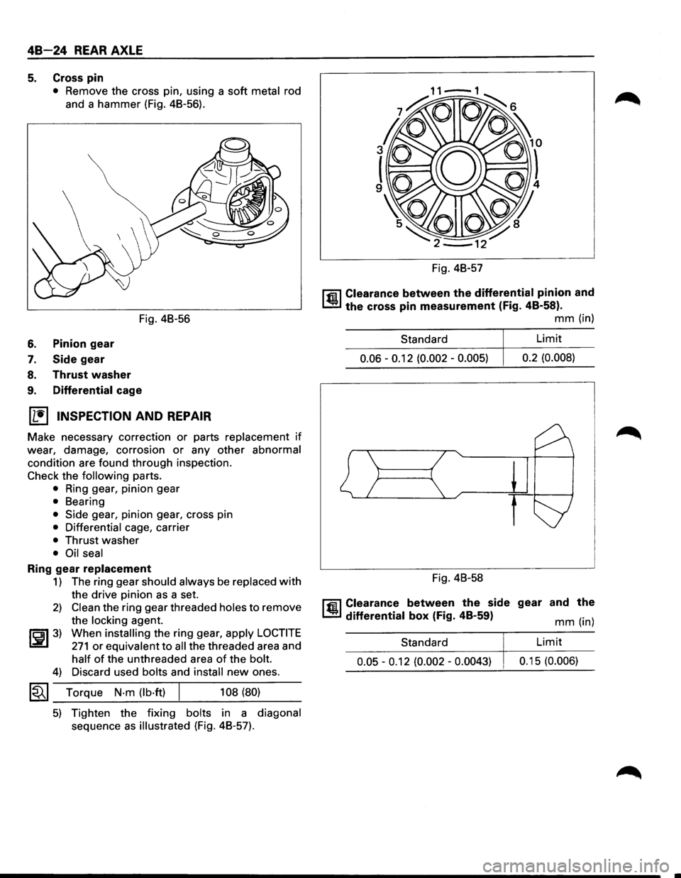
5. Cross pin
• Remove the cross pin, using a soft metal rod
and a hammer (Fig. 48-56).
Fig. 48-56
6. Pinion gear
7. Side gear
8. Thrust washer
9. Differential cage
(1!] INSPECTION AND REPAIR
Make necessary correction or parts replacement if
wear, damage, corrosion or any other abnormal
condition are found through inspection.
Check the following parts.
• Ring gear, pinion gear
• Bearing
• Side gear, pinion gear, cross pin
• Differential cage, carrier
• Thrust washer
• Oil seal
Ring gear replacement
1) The ring gear should always be replaced with
the drive pinion as a set.
2) Clean the ring gear threaded holes to remove
the
locking agent.
~~~3) When installing the ring gear, apply LOCTITE
271 or equivalent to all the threaded area and
half of the unthreaded area of the bolt.
4) Discard used bolts and install new ones.
1~1 Torque N·m (lb·ft) 108 (80)
5) Tighten the fixing bolts in a diagonal
sequence as illustrated (Fig. 48-57). Fig.
48-57
l'fil Clearance between the differential pinion and
1..!:.1 the cross pin measurement (Fig. 48-58).
mm (in)
Standard Limit
0.06 -0.12
(0.002 -0.005) 0.2
(0.008)
Fig. 48-58
l'fil Clearance between the side gear and the
1..!:.1 differential box (Fig. 48-59) mm (in)
Standard
Limit
0.05 -0.12 (0.002 -0.0043) 0.1 5 (0.006)