oil level ISUZU TROOPER 1995 Owner's Guide
[x] Cancel search | Manufacturer: ISUZU, Model Year: 1995, Model line: TROOPER, Model: ISUZU TROOPER 1995Pages: 1928
Page 909 of 1928
w CJ s: a: w Cl)
w ..... CJ :E w > I z 0
AUTOMATIC TRANSMISSION (4L30..E) 7 A-37
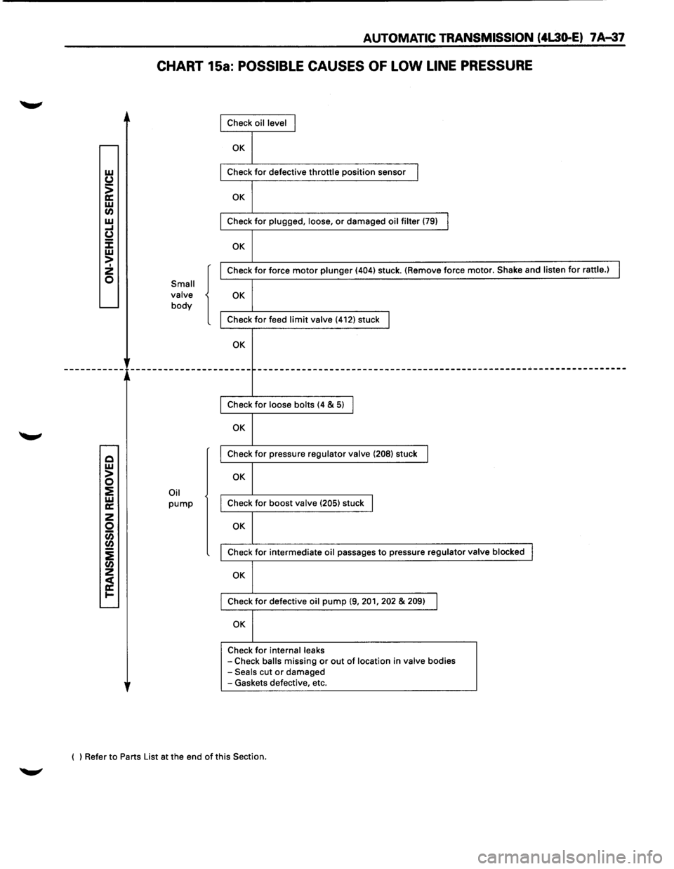
CHART 15a: POSSIBLE CAUSES OF LOW LINE PRESSURE
Small
valve
body
Oil pump
{
Check oil level I
OK
Check for defective throttle position sensor I
OK
Check for plugged, loose, or damaged oil filter (79) I
OK
Check for force motor plunger (404) stuck. (Remove force motor. Shake and listen for rattle.) I
OK
Check for feed limit valve (412) stuck I
OK
------------------------------------------------------------------------
Check for loose bolts (4 & 5) I
OK
Check for pressure regulator valve (208) stuck I
OK
Check for boost valve (205) stuck I
OK
Check for intermediate oil passages to pressure regulator valve blocked I
OK
Check for defective oil pump (9, 201, 202 & 209) I
OK
Check for internal leaks -Check balls missing or out of location in valve bodies -Seals cut or damaged
-Gaskets defective, etc.
( ) Refer to Parts List at the end
of this Section.
Page 911 of 1928
AUTOMATIC TRANSMISSION (4L30-E) 7 A-39
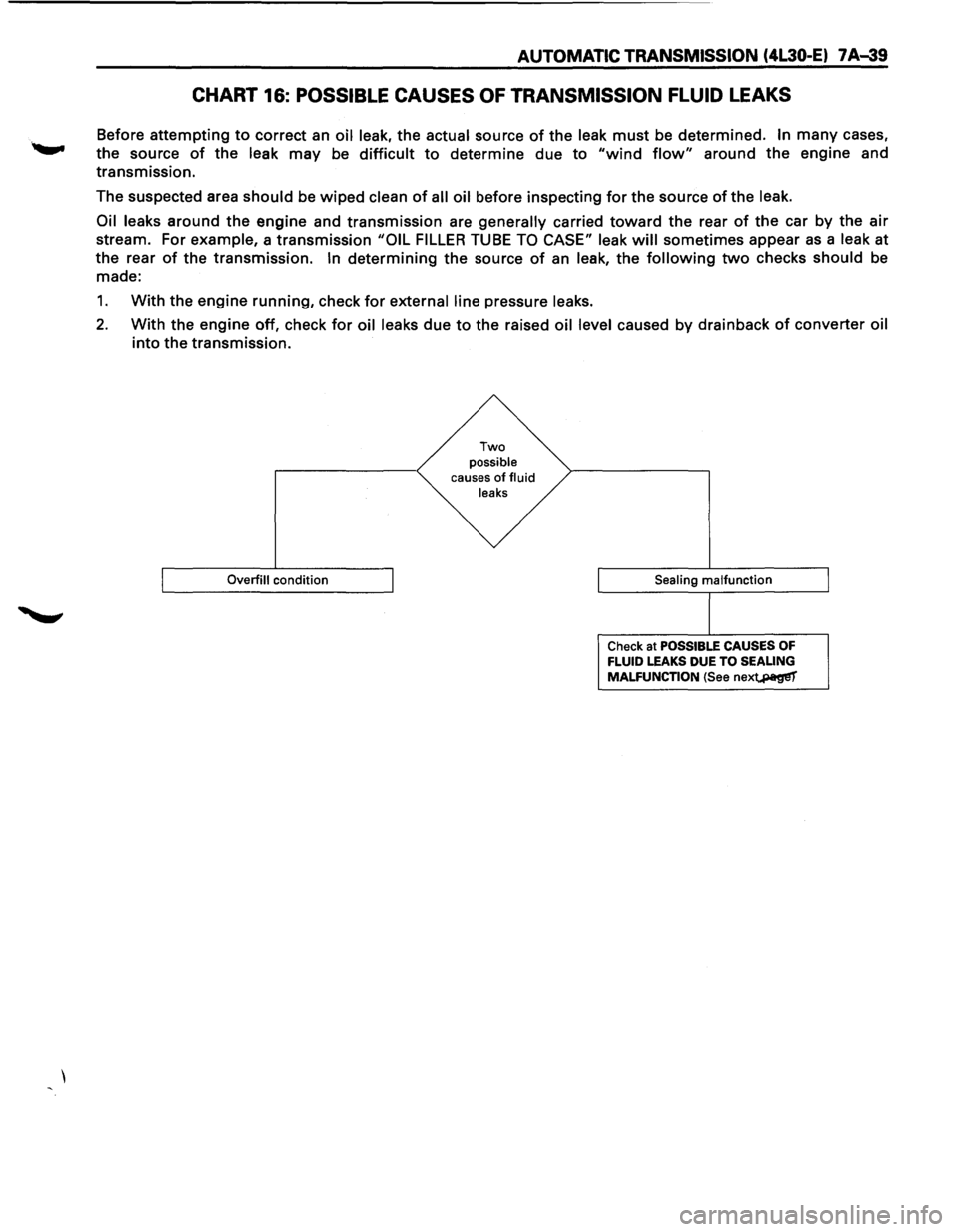
CHART 16: POSSIBLE CAUSES OF TRANSMISSION FLUID LEAKS
Before attempting to correct an oil leak, the actual source of the leak must be determined. In many cases,
the source
of the leak may be difficult to determine due to "wind flow" around the engine and
transmission.
The suspected area
should be wiped clean of all oil before inspecting for the source of the leak.
Oil leaks
around the engine and transmission are generally carried toward the rear of the car by the air
stream. For example, a transmission "OIL FILLER TUBE TO CASE" leak will sometimes appear as a leak at
the rear
of the transmission. In determining the source of an leak, the following two checks should be
made:
1. With the engine running, check for external line pressure leaks.
2. With the engine off, check for oil leaks due to the raised oil level caused by drainback of converter oil
into the transmission.
Overfill condition
Two possible causes of fluid
leaks
Sealing
malfunction
Check at POSSIBLE CAUSES OF FLUID LEAKS DUE TO SEALING
MALFUNCTION (See nex~
Page 913 of 1928
STALL TEST
The stall test allows you to check the transmission for
internal abrasion and the oneway clutch for slippage.
Torque converter performance can also be evaluated.
The
stall test results together with the road test results
will identify transmission components requiring ser
vicing or adjustment.
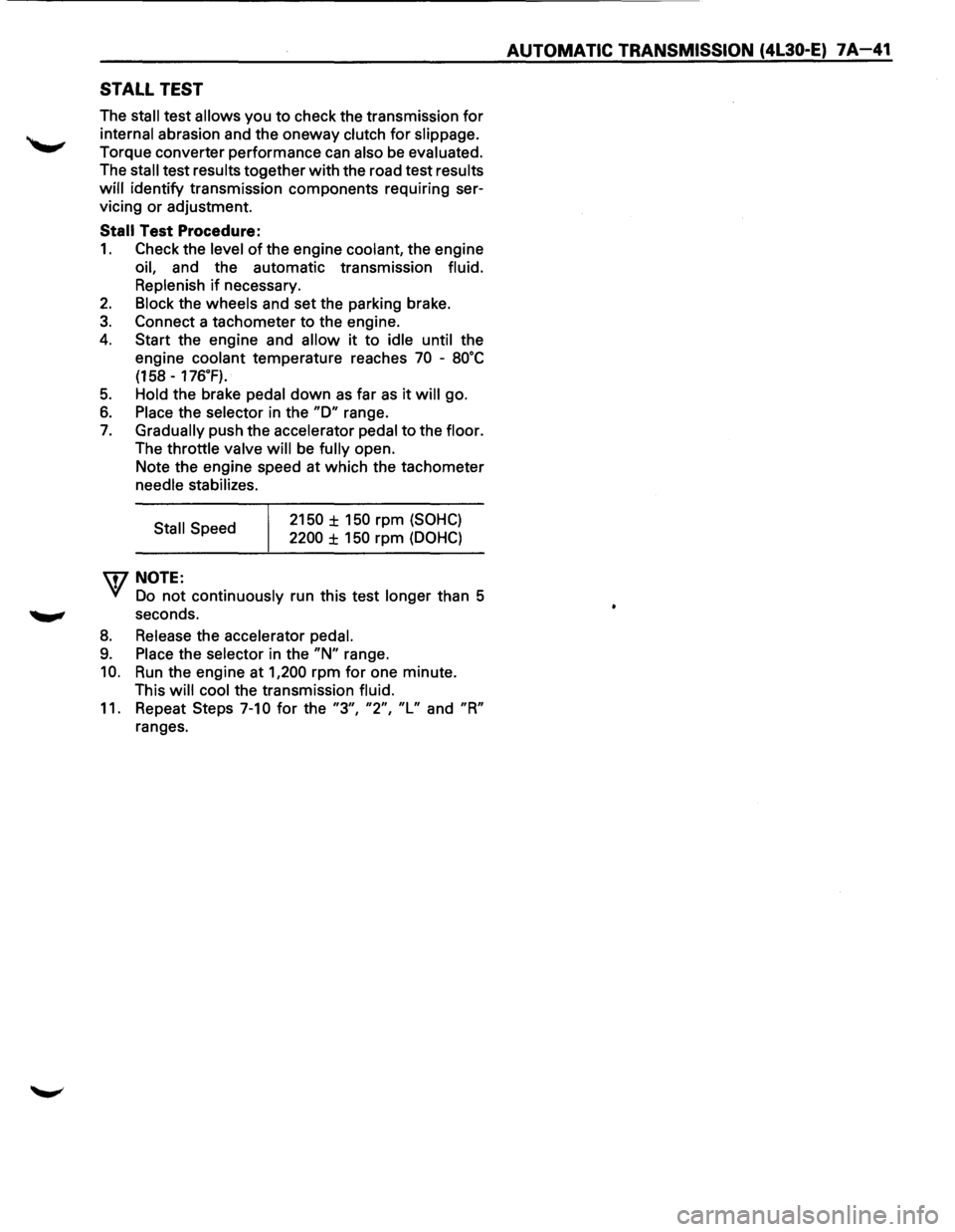
Stall Test Procedure:
1. Check the level of the engine coolant, the engine
oil, and the automatic transmission fluid.
Replenish
if necessary.
2. Block the wheels and set the parking brake.
3. Connect a tachometer to the engine.
4. Start the engine and allow it to idle until the
engine coolant temperature reaches
70 -8o·c
(158 -176.F).
5. Hold the brake pedal down as far as it will go.
6. Place the selector in the "D" range.
7. Gradually push the accelerator pedal to the floor.
The throttle valve
will be fully open.
Note the engine speed at which the tachometer
needle stabilizes.
Stall Speed
\fl NOTE:
2150 ± 150 rpm (SOHC)
2200 ± 150 rpm (DOHC)
VI Do not continuously run this test longer than 5
........, seconds.
8. Release the accelerator pedal.
9. Place the selector in the "N" range.
10. Run the engine at 1,200 rpm for one minute.
This
will cool the transmission fluid.
11. Repeat Steps 7-10 for the "3", "2", "L" and "R"
ranges.
AUTOMATIC TRANSMISSION (4L30-E) 7A-41
Page 914 of 1928
7 A-42 AUTOMATIC TRANSMISSION (4L30-E)
LINE PRESSURE TEST
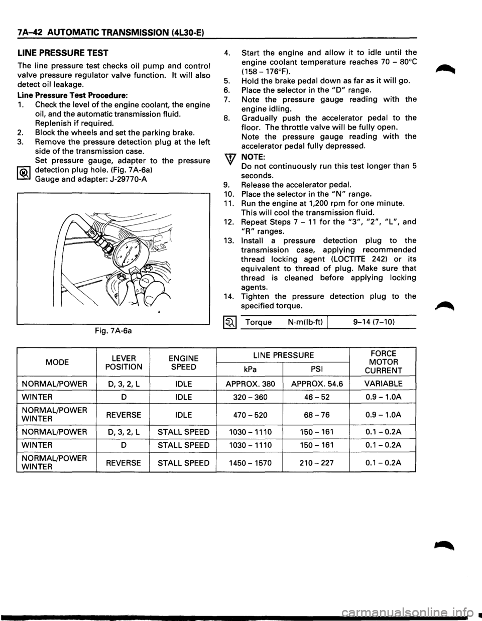
The line pressure test checks oil pump and control
valve
pressure regulator valve function. It will also
detect oil leakage.
Line Pressure Test Procedure:
1. Check the level of the engine coolant, the engine
oil, and the automatic transmission fluid.
Replenish
if required.
2. Block the wheels and set the parking brake.
3. Remove the pressure detection plug at the left
side of the transmission case.
Set pressure gauge, adapter
to the pressure
l"iC\1 detection plug hole. (Fig. 7 A-6a)
~ Gauge and adapter: J-29770-A
Fig. 7A-6a
LEVER ENGINE
MODE
POSITION
SPEED
NORMAL/POWER D,3,2, L IDLE
WINTER D IDLE
NORMAL/POWER REVERSE IDLE WINTER
NORMAL/POWER
D,3,2,L STALL SPEED
WINTER D STALL SPEED
NORMAL/POWER REVERSE STALL SPEED WINTER
4.
5.
6.
7.
8.
9.
10.
11.
Start the engine and allow it to idle until the
engine
coolant temperature reaches 70 -80°C
(158-176°F).
Hold
the brake pedal down as far as it will go.
Place the selector in the "D" range.
Note the pressure gauge reading
with the
engine
idling.
Gradually
push the accelerator pedal to the
floor. The throttle valve will be fully open.
Note the pressure gauge reading
with the
accelerator
pedal fully depressed.
NOTE:
Do not continuously run this test longer than 5
seconds.
Release the accelerator pedal.
Place
the selector in the "N" range.
Run the engine at
1,200 rpm for one minute.
This
will cool the transmission fluid.
12. Repeat Steps 7-11 for the "3", "2", "L", and
"R" ranges.
13.
Install a pressure detection plug to the
transmission case,
applying recommended
thread
locking agent (LOCTITE 242) or its
equivalent to thread
of plug. Make sure that
thread is cleaned before applying locking
agents.
14. Tighten the pressure detection plug to the
specified torque.
~~~ Torque N·mOb·ft) / 9-14 (7-10)
LINE
PRESSURE FORCE
MOTOR kPa PSI CURRENT
APPROX. 380 APPROX. 54.6 VARIABLE
320-360 46-52 0.9 -1.0A
470-520 68-76 0.9 -1.0A
1030-1110 150-161 0.1-0.2A
1030-1110 150-161 0.1-0.2A
1450-1570 210-227 0.1-0.2A
•
Page 1027 of 1928
... ......,.
AUTOMATIC TRANSMISSION (4L30-E) 7A-155
ON-VEHICLE SERVICE
CHECKING TRANSMISSION FLUID
LEVEL
1. Park the vehicle on level ground.
2. Apply the parking brake.
3. Place the automatic transmission in "Park" and
start the engine.
Allow the engine to idle for
two minutes.
4. With the brakes applied, move the shifter lever
through all the gear ranges, ending in "Park".
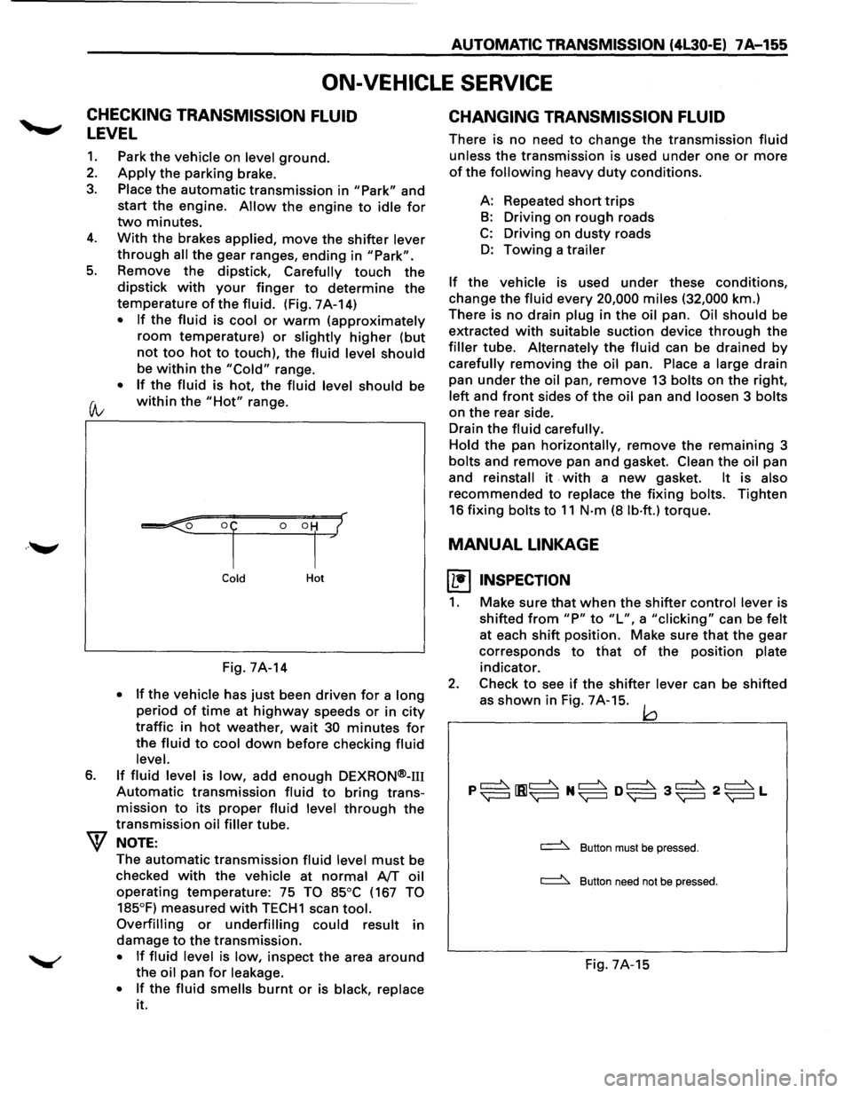
5. Remove the dipstick, Carefully touch the
dipstick with your finger to determine the
temperature of the fluid. (Fig. 7A-14)
• If the fluid is cool or warm (approximately
room temperature) or slightly higher (but
not too hot to touch), the fluid level should
be within the "Cold" range.
• If the fluid is hot, the fluid level should be
(A; within the "Hot" range.
6.
Cold Hot
Fig. 7A-14
• If the vehicle has just been driven for a long
period of time at highway speeds or in city
traffic in hot weather, wait 30 minutes for
the fluid to cool down before checking fluid
level.
If fluid level is low, add enough DEXRON®-m
Automatic transmission fluid to bring trans
mission
to its proper fluid level through the
transmission oil filler tube.
NOTE:
The automatic transmission fluid level must be
checked
with the vehicle at normal AfT oil
operating temperature: 75 TO 85°C (167 TO
185°F)
measured with TECH1 scan tool.
Overfilling or underfilling could result in
damage
to the transmission.
• If fluid level is low, inspect the area around
the oil pan for leakage.
•
If the fluid smells burnt or is black, replace
it.
CHANGING TRANSMISSION FLUID
There is no need to change the transmission fluid
unless the transmission is used under one or more
of the following heavy duty conditions.
A: Repeated
short trips
B: Driving on rough roads
C: Driving on dusty roads
D: Towing a trailer
If the vehicle is used under these conditions,
change the fluid every 20,000 miles (32,000 km.)
There is
no drain plug in the oil pan. Oil should be
extracted
with suitable suction device through the
filler tube. Alternately the fluid can be drained by
carefully removing the oil pan. Place a large drain
pan
under the oil pan, remove 13 bolts on the right,
left and front sides of the oil pan and loosen 3 bolts
on the rear side.
Drain
the fluid carefully.
Hold
the pan horizontally, remove the remaining 3
bolts and remove pan and gasket. Clean the oil pan
and
reinstall it . with a new gasket. It is also
recommended to replace the fixing bolts. Tighten
16 fixing bolts to 11 N·m (8 lb·ft.) torque.
MANUAL LINKAGE
~ INSPECTION
1. Make sure that when the shifter control lever is
shifted
from "P" to "L", a "clicking" can be felt
at each shift position. Make sure that the gear
corresponds
to that of the position plate
indicator.
2. Check to see if the shifter lever can be shifted
as
shown in Fig. 7A-15. jQ
~ Button must be pressed.
~ Button need not be pressed.
Fig. 7A-15
Page 1032 of 1928
7A-160 AUTOMATIC TRANSMISSION (4L30-E)
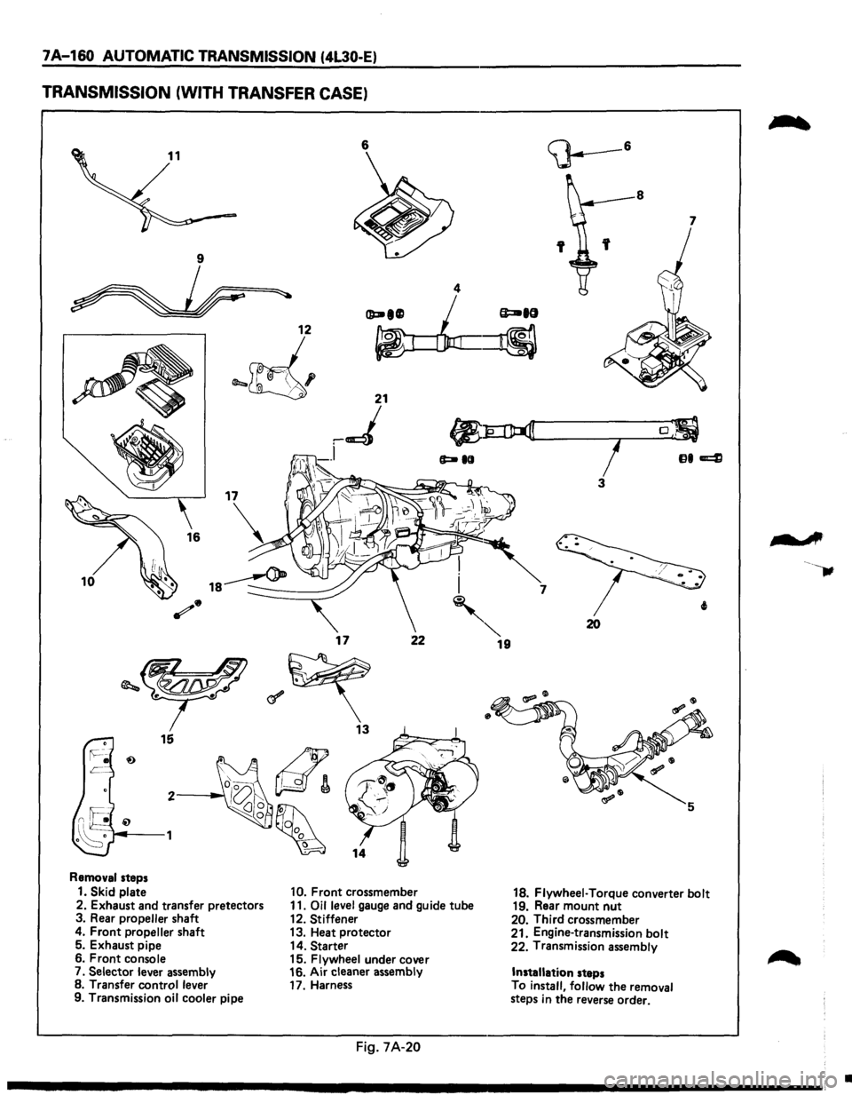
TRANSMISSION (WITH TRANSFER CASE)
6
I
10 i
'
17 22
Removal steps
1. Skid plate 10. Front crossmember
2. Exhaust and transfer pretectors 11. Oil level gauge and guide tube
3. Rear propeller shaft
12. Stiffener
4. Front propeller shaft 13. Heat protector
5. Exhaust pipe
14. Starter
6. Front console
15. Flywheel under cover
7.
Selector lever assembly 16.
Air cleaner assembly
8. Transfer control lever
17. Harness
9. Transmission
oil cooler pipe
Fig. 7A-20
""' 19
8
7
7
20
18. Flywheel· Torque converter bolt 19. Rear mount nut 20. Third crossmember
21. Engine-transmission bolt
22. Transmission assembly
Installation steps
To
install, follow the removal
steps in the reverse order.
-A
•
Page 1033 of 1928
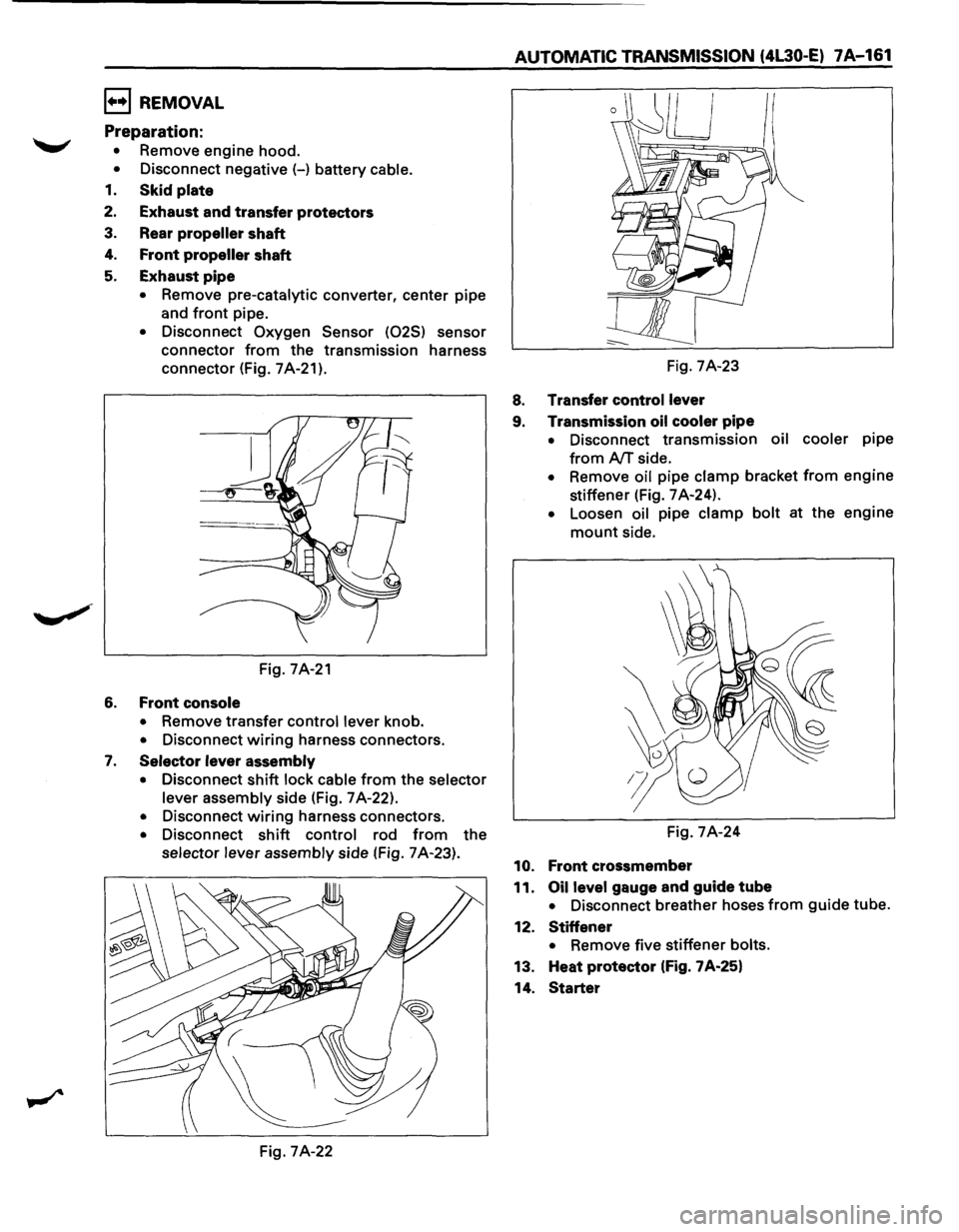
1••1 REMOVAL
Preparation:
• Remove engine hood.
• Disconnect negative (-) battery cable.
1. Skid plate
2. Exhaust and transfer protectors
3. Rear propeller shaft
4. Front propeller shaft
5. Exhaust pipe
• Remove pre-catalytic converter, center pipe
and
front pipe.
• Disconnect Oxygen Sensor (025) sensor
connector
from the transmission harness
connector (Fig.
7A-21).
Fig. 7A-21
6. Front console
• Remove transfer control lever knob.
• Disconnect wiring harness connectors.
7. Selector lever assembly
• Disconnect shift lock cable from the selector
lever assembly
side (Fig. 7 A-22).
• Disconnect wiring harness connectors.
• Disconnect shift control rod from the
selector lever assembly side (Fig. 7 A-23).
Fig. 7A-22
AUTOMATIC TRANSMISSION (4L30·E) 7A-161
Fig. 7A-23
8. Transfer control lever
9. Transmission oil cooler
pipe
• Disconnect transmission oil cooler pipe
from AfT side.
• Remove oil pipe clamp bracket from engine
stiffener (Fig.
7 A-24).
• Loosen oil pipe clamp bolt at the engine
mount side.
Fig.
7A-24
10. Front crossmember
11.
Oil level gauge and guide tube
• Disconnect breather hoses from guide tube.
12.
Stiffener
• Remove five stiffener bolts.
13. Heat protector (Fig. 7A-25}
14.
Starter
Page 1042 of 1928
7 A-170 AUTOMATIC TRANSMISSION (4L30-E)
TRANSMISSION OIL TEMPERATURE
SENSOR (ADAPTER CASE)
1•+1 REMOVAL
Preparation:
• Disconnect negative (-) battery cable.
•
Remove exhaust protector and exhaust pipe.
• Drain fluid.
•
Refer to "CHANGING TRANSMISSION FLUID".
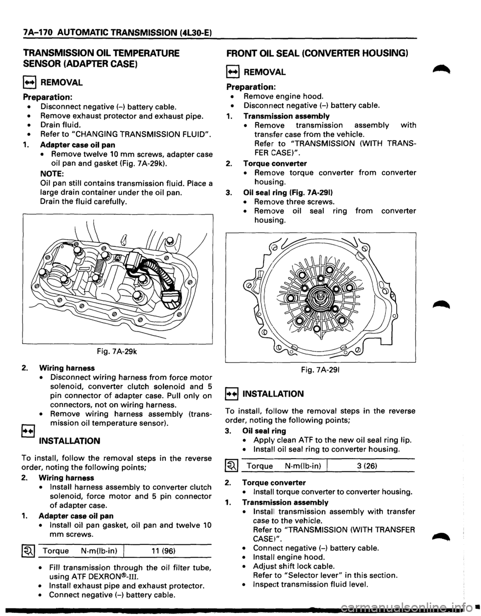
1. Adapter case oil pan
• Remove twelve 10 mm screws, adapter case
oil pan and gasket (Fig. 7 A-29k).
NOTE:
Oil
pan still contains transmission fluid. Place a
large drain container under the oil pan.
Drain the
fluid carefully.
Fig. 7A-29k
2. Wiring harness
• Disconnect wiring harness from force motor
solenoid, converter clutch solenoid and 5
pin connector
of adapter case. Pull only on
connectors,
not on wiring harness.
• Remove wiring harness assembly (trans
B mission oil temperature sensor).
INSTALLATION
To install, follow the removal steps in the reverse
order, noting the
following points;
2.
Wiring harness
• Install harness assembly to converter clutch
solenoid,
force motor and 5 pin connector
of adapter case.
1. Adapter case oil pan
• Install oil pan gasket, oil pan and twelve 10
mm screws.
~~~ Torque N·mOb·in) I 11 (96)
• Fill transmission through the oil filter tube,
using ATF
DEXRON®-111.
• Install exhaust pipe and exhaust protector.
• Connect negative (-) battery cable.
FRONT OIL SEAL (CONVERTER HOUSING)
l++l REMOVAL
Preparation:
• Removt~ engine hood.
• Disconnect negative (-) battery cable.
1. Transmission assembly
•
Remove transmission assembly with
transfer case from the vehicle.
Refer to "TRANSMISSION (WITH TRANS
FER CASE)".
2. Torque converter
• Remove torque converter from converter
housing.
3.
Oil seal ring (Fig. 7 A-291)
• Remove three screws.
• Remove oil seal ring from converter
housing.
Fig.
7A-291
I++IINSTALLATION
To install, follow the removal steps in the reverse
order, noting the
following points;
3. Oil seal ring
• Apply clean ATF to the new oil seal ring lip.
• Install oil seal
ring to converter housing.
~~~ Torque N·mOb·in) I 3 (26)
2. Torque converter
• Install torque converter to converter housing.
1. Transmission assembly
• Install
transmission assembly with transfer
case
to the vehicle.
Refer to "TRANSMISSION (WITH TRANSFER
CASE I".
• Connoct negative (-) battery cable.
• Install
engine hood.
• Adjust shift lock cable.
Refer to "Selector lever" in this section.
• Inspect transmission fluid level.
•
Page 1043 of 1928
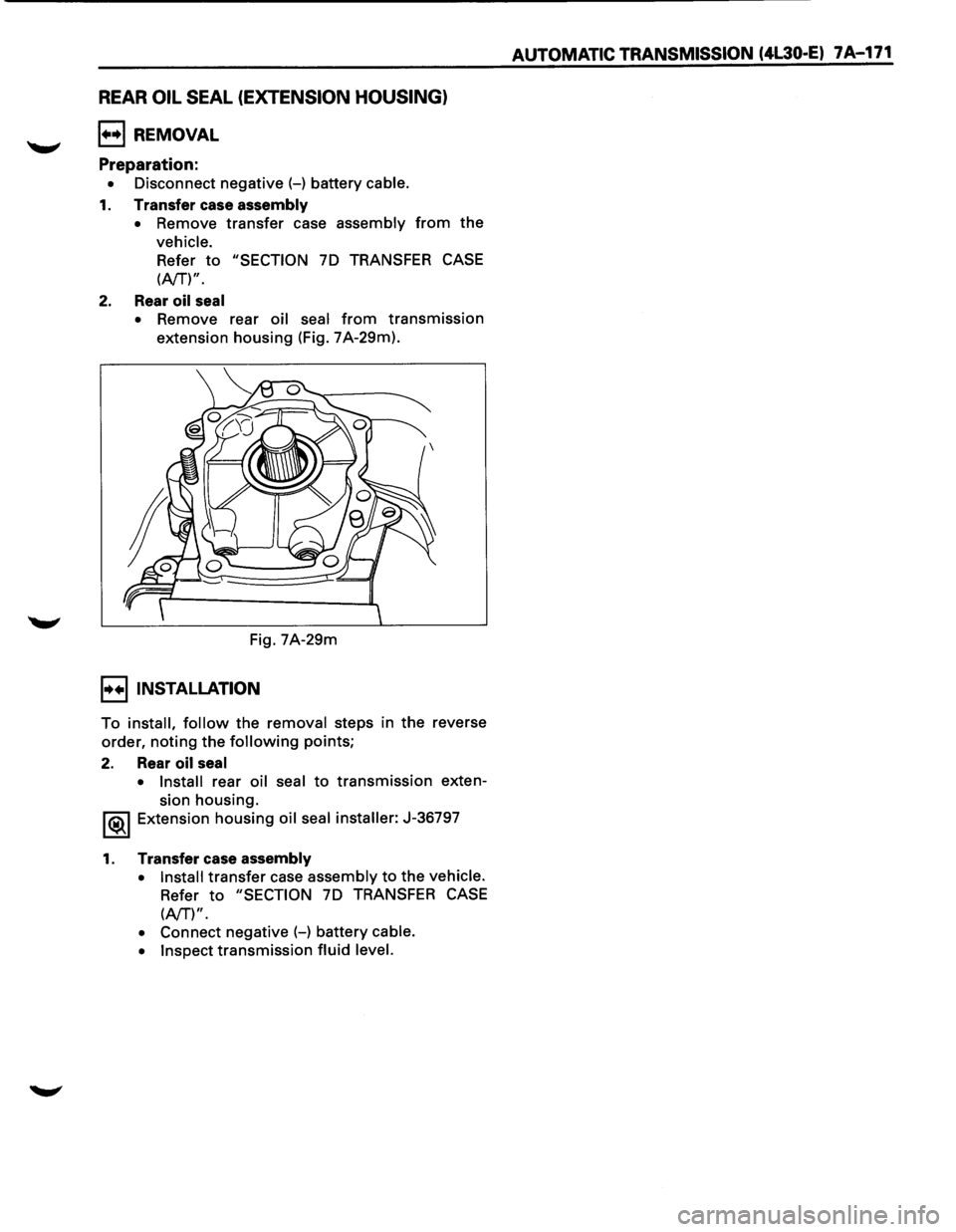
REAR OIL SEAL (EXTENSION HOUSING)
l••l REMOVAL
Preparation:
• Disconnect negative (-) battery cable.
1. Transfer case assembly
• Remove transfer case assembly from the
vehicle.
Refer to "SECTION 70 TRANSFER CASE
(AfT')".
2. Rear oil seal
• Remove rear oil seal from transmission
extension housing (Fig. 7A-29m).
Fig. 7A-29m
I••IINSTALLATION
To install, follow the removal steps in the reverse
order,
noting the following points;
2. Rear oil seal
• Install rear oil seal to transmission exten
sion housing.
1®..1 Extension housing oil seal installer: J-36797
1. Transfer case assembly
• Install transfer case assembly to the vehicle.
Refer to "SECTION 70 TRANSFER CASE
(AfT')".
• Connect negative (-) battery cable.
• Inspect
transmission fluid level.
AUTOMATIC TRANSMISSION (4L30·E) 7A-171
Page 1511 of 1928
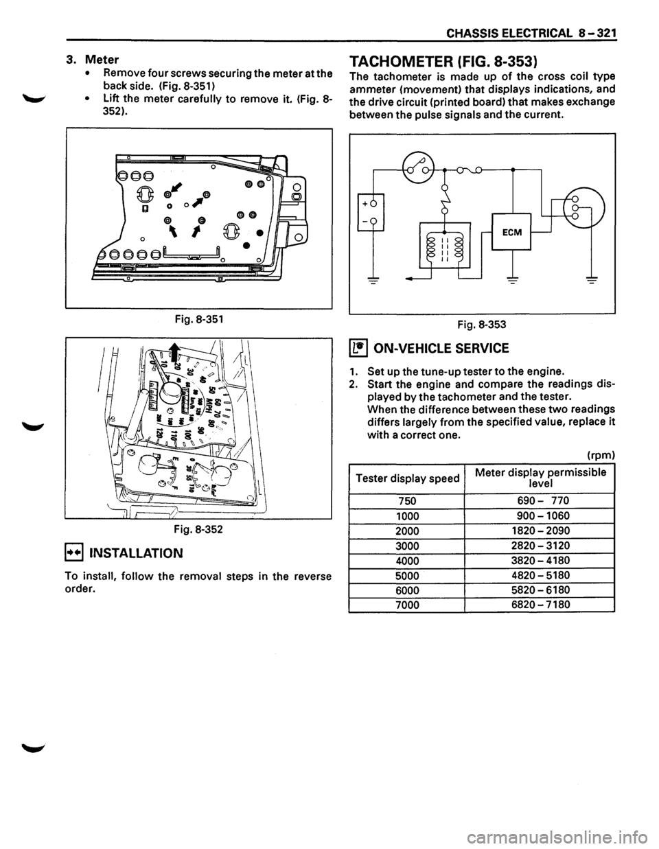
3. Meter
• Remove four screws securing the meter at the
back side. (Fig.
8-351)
• Lift the meter carefully to remove it. (Fig. 8-
352).
0
q;J"' 0
0 0 0,
0 0
0 I
Fig. 8-351
Fig. 8-352
E) INSTALLATION
00
0
To install, follow the removal steps in the reverse
order.
CHASSIS ELECTRICAL 8-321
TACHOMETER (FIG. 8-353)
The tachometer is made up of the cross coil type
ammeter (movement) that displays indications, and
the drive circuit (printed board)
that makes exchange
between the
pulse signals and the current.
Fig.
8-353
(1!1 ON-VEHICLE SERVICE
1. Set up the tune-up tester to the engine.
2. Start the engine and compare the readings dis
played by the tachometer and the tester.
When the difference between these
two readings
differs
largely from the specified value, replace it
with a correct one.
(rpm)
Tester
display speed Meter
display permissible level
750 690-770
1000
900-1060
2000 1820-2090
3000 2820-3120
4000 3820-4180
5000 4820-5180
6000 5820-6180
7000 6820-7180