oil level ISUZU TROOPER 1995 User Guide
[x] Cancel search | Manufacturer: ISUZU, Model Year: 1995, Model line: TROOPER, Model: ISUZU TROOPER 1995Pages: 1928
Page 280 of 1928
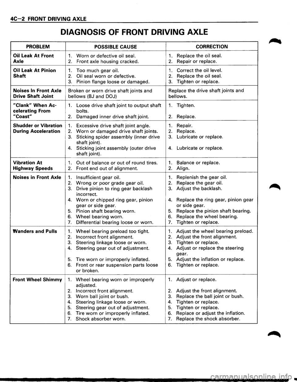
4C-2 FRONT DRIVING AXLE
DIAGNOSIS OF FRONT DRIVING AXLE
PROBLEM POSSIBLE CAUSE CORRECTION
Oil
Leak At Front 1. Worn or defective oil seal. 1. Replace the oil seal.
Axle 2. Front axle housing cracked. 2. Repair or replace.
Oil Leak At Pinion 1. Too much gear oil. 1. Correct the oil level.
Shaft 2. Oil seal worn or defective. 2. Replace the oil seal.
3. Pinion flange loose or damaged. 3. Tighten or replace.
Noises In Front Axle Broken or worn drive shaft joints and Replace
the drive shaft joints and
Drive Shaft Joint bellows (BJ and DOJ) bellows.
"Clank" When Ac-1. Loose drive shaft joint to output shaft 1. Tighten.
celerating From bolts.
"Coast" 2. Damaged inner drive shaft joint. 2. Replace.
Shudder or Vibration 1. Excessive drive shaft joint angle. 1. Repair.
During Acceleration 2. Worn or damaged drive shaft joints. 2. Replace.
3. Sticking spider assembly (inner drive 3. Lubricate or replace.
shaft joint).
4. Sticking joint assembly (outer drive 4. Lubricate or replace.
shaft joint).
Vibration At 1. Out of balance or out of round tires. 1. Balance or replace.
Highway Speeds 2. Front end out of alignment. 2. Align.
Noises in Front Axle 1. Insufficient gear oil. 1. Replenish the gear oil.
2. Wrong or poor grade gear oil. 2. Replace the gear oil.
3. Drive pinion to ring gear backlash 3. Adjust the backlash.
incorrect.
4. Worn or chipped ring gear, pinion 4. Replace the ring gear, pinion gear
gear
or side gear. or side gear.
5. Pinion shaft bearing worn. 5. Replace the pinion shaft bearing.
6. Wheel bearing worn. 6. Replace the wheel bearing.
7. Differential bearing loose or worn. 7. Tighten or replace.
Wanders and Pulls 1. Wheel bearing preload too tight. 1. Adjust the wheel bearing preload.
2. Incorrect front alignment. 2. Adjust the front alignment.
3. Steering linkage loose or worn. 3. Tighten or replace.
4. Steering gear out of adjustment. 4. Adjust or replace the steering
gear.
5. Tire worn or improperly inflated. 5. Adjust the inflation or replace.
6. Front or rear suspension parts loose 6. Tighten or replace.
or broken.
Front Wheel Shimmy 1. Wheel bearing worn or improperly 1. Adjust or replace.
adjusted.
2. Incorrect front alignment. 2. Adjust the front alignment.
3. Worn ball joint or bush. 3. Replace the ball joint or bush.
4. Steering linkage loose or worn. 4. Tighten or replace.
5. Steering gear out of adjustment. 5. Tighten or replace.
6. Tire worn or improperly inflated. 6. Replace or adjust the inflation.
7. Shock absorber worn. 7. Replace the shock absorber.
..
Page 323 of 1928
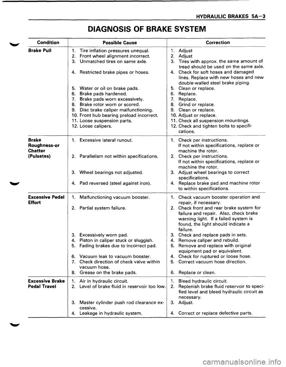
HYDRAULIC BRAKES 5A-3
DIAGNOSIS OF BRAKE SYSTEM
Condition
Possible Cause Correction
Brake
Pull 1. Tire inflation pressures unequal. 1. Adjust
2. Front wheel alignment incorrect. 2. Adjust
3. Unmatched tires on same axle. 3. Tires with approx. the same amount of
tread should be used on the same axle.
4. Restricted brake pipes or hoses. 4. Check for soft hoses and damaged
lines. Replace with new hoses and new
double-walled steel brake piping.
5. Water or oil on brake pads. 5. Clean or replace.
6. Brake pads hardened. 6. Replace.
7. Brake pads worn excessively. 7. Replace.
8. Brake rotor worn or scored. 8. Grind or replace.
9. Disc brake caliper malfunctioning. 9. Clean or replace.
10. Front hub bearing preload incorrect. 10. Adjust or replace.
11. Loose suspension parts. 11. Check all suspension mountings.
12. Loose
calipers. 12. Check and tighten bolts to specifi-
cations.
Brake 1. Excessive lateral runout. 1. Check per instructions.
Roughness-or If not within specifications, replace or
Chatter machine the rotor.
(Pulsates) 2. Parallelism not within specifications. 2. Check per instructions.
If not within specifications, replace or
machine the rotor.
3. Wheel bearings not adjusted. 3. Adjust wheel bearings to correct
specifications.
4. Pad reversed (steel against iron). 4. Replace brake pad and machine rotor
to within specifications.
Excessive Pedal 1. Malfunctioning vacuum booster. 1. Check vacuum booster operation and
Effort repair, if necessary.
2. Partial system failure. 2. Check front and rear brake system for
failure and repair. Also, check brake
warning
light. If a failed system
is
found, the
light should indicate a
failure.
3. Excessively worn pad. 3. Check and replace pads in sets.
4. Piston in caliper stuck or sluggish. 4. Remove caliper and rebuild.
5. Fading brakes due to incorrect pad. 5. Remove and replace with original
equipment pad or equivalent.
6. Vacuum leak to vacuum booster. 4. Check for ruptured or loose hose.
7. Check direction of check valve within 5. Correct vacuum hose direction.
vacuum hose.
8. Grease on the brake pads. 6. Replace or clean.
Excessive Brake 1. Air in hydraulic circuit. 1. Bleed hydraulic circuit.
Pedal Travel 2. Level of brake fluid in reservoir too low. 2. Replenish brake fluid reservoir to speci-
fied
level and bleed hydraulic circuit as
necessary.
3. Master cylinder push rod clearance ex-3. Adjust.
cessive.
4. Leakage in hydraulic system. 4. Correct or replace defective parts.
Page 324 of 1928
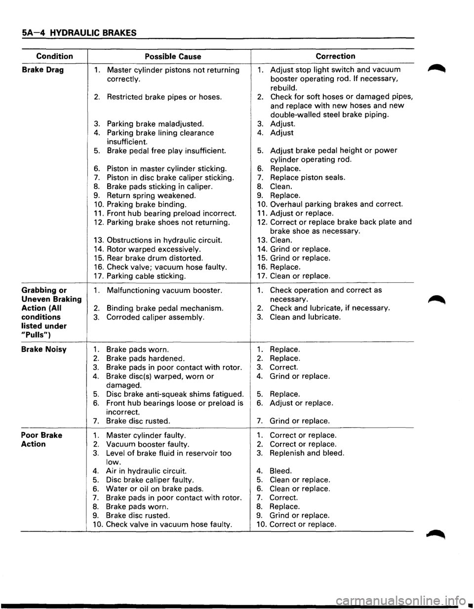
SA-4 HYDRAULIC BRAKES
Condition Possible Cause Correction
Brake Drag
1. Master cylinder pistons not returning 1. Adjust stop light switch and vacuum
correctly. booster operating rod. If necessary,
rebuild.
2. Restricted brake pipes or hoses. 2. Check for soft hoses or damaged pipes,
and
replace with new hoses and new
double-walled steel brake piping.
3. Parking brake maladjusted. 3. Adjust.
4. Parking brake lining clearance 4. Adjust
insufficient.
5. Brake pedal free play insufficient. 5. Adjust brake pedal height or power
cylinder operating rod.
6. Piston in master cylinder sticking. 6. Replace.
7. Piston in disc brake caliper sticking. 7. Replace piston seals.
8. Brake pads sticking in caliper. 8. Clean.
9. Return spring weakened. 9. Replace.
10. Praking brake binding. 10. Overhaul parking brakes and correct.
11. Front hub bearing preload incorrect. 11.
Adjust or replace.
12. Parking brake shoes not returning. 12.
Correct or replace brake back plate and
brake shoe
as necessary.
13. Obstructions in hydraulic circuit. 13. Clean.
14. Rotor warped excessively. 14.
Grind or replace.
15. Rear brake drum distorted. 15.
Grind or replace.
16. Check valve; vacuum hose faulty. 16. Replace.
17. Parking cable sticking. 17. Clean or replace.
Grabbing
or 1. Malfunctioning vacuum booster. 1. Check operation and correct as
Uneven Braking necessary.
Action
(All 2. Binding brake pedal mechanism. 2. Check and lubricate, if necessary.
conditions
3. Corroded caliper assembly. 3. Clean and lubricate.
listed
under
"Pulls")
Brake Noisy 1 . Brake pads worn. 1. Replace.
2. Brake pads hardened. 2. Replace.
3. Brake pads in poor contact with rotor. 3. Correct.
4. Brake disc(s) warped, worn or 4. Grind or replace.
damaged.
5. Disc brake anti-squeak shims fatigued. 5. Replace.
6. Front hub bearings loose or preload is 6. Adjust or replace.
incorrect.
7. Brake disc rusted. 7. Grind or replace.
Poor Brake 1. Master cylinder faulty. 1. Correct or replace.
Action 2. Vacuum booster faulty. 2. Correct or replace.
3. Level of brake fluid in reservoir too 3. Replenish and bleed.
low.
4. Air in hydraulic circuit. 4. Bleed.
5. Disc brake caliper faulty. 5. Clean or replace.
6. Water or oil on brake pads. 6. Clean or replace.
7. Brake pads in poor contact with rotor. 7. Correct.
8. Brake pads worn. 8. Replace.
9. Brake disc rusted. 9. Grind or replace.
10. Check valve in vacuum hose faulty. 10. Correct or replace.
•
Page 325 of 1928
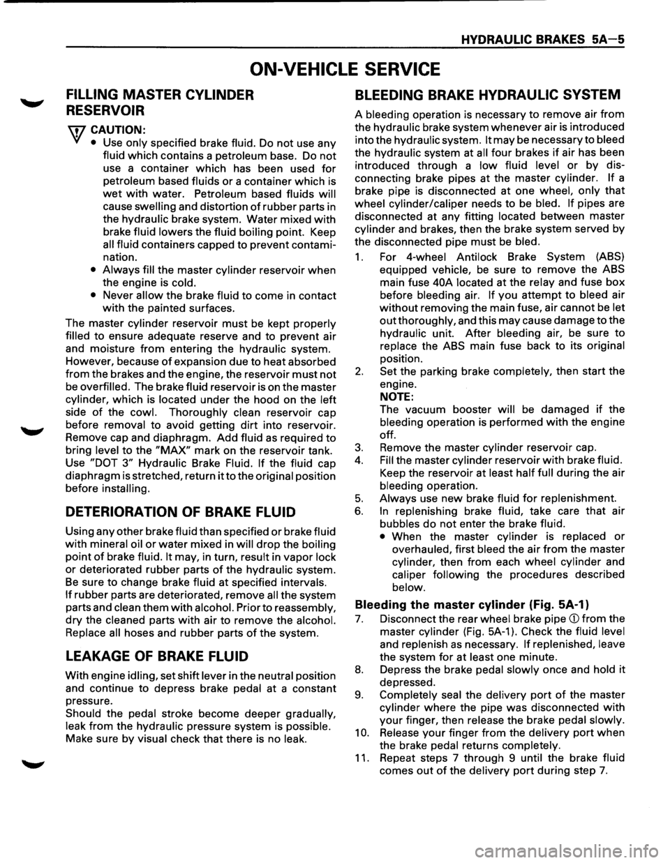
HYDRAULIC BRAKES 5A-5
ON-VEHICLE SERVICE
FILLING MASTER CYLINDER
RESERVOIR
'\fl CAUTION:
'VI • Use only specified brake fluid. Do not use any
fluid which contains a petroleum base. Do not
use a container which has been used for
petroleum based fluids or a container which is
wet with water. Petroleum based fluids will
cause swelling and distortion of rubber parts in
the
hydraulic brake system. Water mixed with
brake fluid lowers the fluid boiling point. Keep
all fluid containers capped to prevent contami
nation.
• Always fill the master cylinder reservoir when
the engine is
cold.
•
Never allow the brake fluid to come in contact
with the painted surfaces.
The master
cylinder reservoir must be kept properly
filled
to ensure adequate reserve and to prevent air
and moisture
from entering the hydraulic system.
However, because
of expansion due to heat absorbed
from the brakes and the engine, the reservoir must not
be overfilled. The brake fluid reservoir is on the master
cylinder, which is located under the hood on the
left
side of the cowl. Thoroughly clean reservoir cap
before
removal to avoid getting dirt into reservoir.
Remove cap and diaphragm.
Add fluid as required to
bring level to the "MAX" mark on the reservoir tank.
Use
"DOT 3" Hydraulic Brake Fluid. If the fluid cap
diaphragm is stretched, return
it to the original position
before
installing.
DETERIORATION OF BRAKE FLUID
Using any other brake fluid than specified or brake fluid
with mineral oil or water mixed in will drop the boiling
point of brake fluid. It may, in turn, result in vapor lock
or deteriorated rubber parts of the hydraulic system.
Be sure to change brake fluid at specified intervals.
If rubber parts are deteriorated, remove all the system
parts and
clean them with alcohol. Prior to reassembly,
dry the cleaned parts with air to remove the alcohol.
Replace all
hoses and rubber parts of the system.
LEAKAGE OF BRAKE FLUID
With engine idling, set shift lever in the neutral position
and continue to depress brake
pedal at a constant
pressure.
Should the pedal stroke become deeper gradually,
leak from the hydraulic pressure system is possible.
Make sure
by visual check that there is no leak.
BLEEDING BRAKE HYDRAULIC SYSTEM
A bleeding operation is necessary to remove air from
the hydraulic brake system whenever air is introduced
into the hydraulic system.
It may be necessary to bleed
the hydraulic system at all four brakes if air has been
introduced through a
low fluid level or by dis
connecting brake pipes at the master cylinder. If a
brake pipe is disconnected at one
wheel, only that
wheel cylinder/caliper needs to be bled. If pipes are
disconnected at any fitting
located between master
cylinder and brakes, then the brake system served by
the disconnected pipe must
be bled.
1. For 4-wheel Antilock Brake System (ABS)
equipped
vehicle, be sure to remove the ABS
main fuse
40A located at the relay and fuse box
before
bleeding air. If you attempt to bleed air
without removing the main fuse, air cannot be let
out thoroughly, and this may cause damage to the
hydraulic unit.
After bleeding air, be sure to
replace the ABS main fuse back to its original
position.
2. Set the parking brake completely, then start the
engine.
NOTE:
The vacuum booster will be damaged if the
bleeding operation is performed with the engine
off.
3. Remove the master cylinder reservoir cap.
4. Fill the master cylinder reservoir with brake fluid.
Keep the reservoir at least half full during the air
bleeding operation.
5. Always use new brake fluid for replenishment.
6. In replenishing brake fluid, take care that air
bubbles do not enter the brake fluid.
•
When the master cylinder is replaced or
overhauled, first bleed the air from the master
cylinder, then from each
wheel cylinder and
caliper following the procedures described
below.
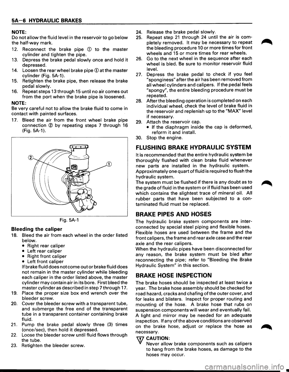
Bleeding the master cylinder (Fig. 5A-1}
7. Disconnect the rear wheel brake pipe
cylinder (Fig. 5A-1 ). Check the fluid level
and replenish as necessary. If replenished, leave
the system for at least one minute.
8. Depress the brake pedal slowly once and hold it
depressed.
9. Completely seal the delivery port of the master
cylinder where the pipe was disconnected with
your finger, then release the brake pedal slowly.
10. Release your finger from the delivery port when
the brake
pedal returns completely.
11. Repeat steps 7 through 9 until the brake fluid
comes out of the delivery port during step 7.
Page 326 of 1928
5A-6 HYDRAULIC BRAKES
NOTE:
Do not allow the fluid level in the reservoir to go below
the half-way mark.
12. Reconnect the brake pipe
(j) to the master
cylinder and tighten the pipe.
13. Depress the brake pedal
slowly once and hold it
depressed.
14. Loosen the rear wheel brake pipe (j) at the master
cylinder (Fig. 5A-1).
15. Retighten the brake pipe, then release the brake
pedal
slowly.
16. Repeat steps 13 through 15 until no air comes out
from the port when the brake pipe is loosened.
NOTE:
Be very careful not to allow the brake fluid to come in
contact
with painted surfaces.
17. Bleed the air from the front wheel brake pipe
connection
® by repeating steps 7 through 16
(Fig.
5A-1 ).
Fig. 5A-1
Bleeding the caliper
18. Bleed the air from each wheel in the order listed
below.
• Right rear caliper
• Left rear caliper
• Right front caliper
• Left front caliper
If brake fluid does not come out or brake fluid does
not remain in the master cylinder while bleeding
each
caliper in the order listed above, the master
cylinder may contain air in its bore. First bleed the
master cylinder
as described in step 7 through 17.
19.
Place the proper size box end wrench over the
bleeder screw.
20. Cover the bleeder screw with a transparent tube,
and submerge the free end
of the transparent
tube in a transparent container containing brake
fluid.
21. Pump the brake pedal slowly three (3) times
(once/sec), then
hold it depressed.
22. Loose the bleeder screw until fluid flows through
the tube.
23. Retighten the bleeder screw.
24. Release the brake pedal slowly.
25. Repeat step 21 through 24 until the air is com
pletely removed.
It may be necessary to repeat
the bleeding procedure
10 or more times for front
wheels and 15 or more times for rear wheels.
26. Go to the next wheel in the sequence after each
wheel is bled.
Be sure to monitor reservoir fluid
level.
27. Depress the brake pedal to check if you feel
"sponginess" after the air has been removed from
all wheel cylinders and calipers. If the pedal feels
"spongy", the entire bleeding procedure must be
repeated.
28. After the bleeding operation is completed on each
individual wheel, check the level
of brake fluid in
the reservoir and replenish up to the
"MAX" level
if necessary.
29. Attach the reservoir cap.
• If the diaphragm inside the cap is deformed,
reform
it and install.
30. Stop the engine.
FLUSHING BRAKE HYDRAULIC SYSTEM
It is recommended that the entire hydraulic system be
thoroughly flushed with clean brake fluid whenever
new parts are
installed in the hydraulic system.
Approximately one quart
of fluid is required to flush the
hydraulic system.
The system
must be flushed if there is any doubt as to
the grade
of fluid in the system or iffluid has been used
which contains the
slightest trace of mineral oil. All
rubber parts that have been subjected to a con
taminated fluid
must be replaced.
BRAKE PIPES AND HOSES
The hydraulic brake system components are inter
connected
by special steel piping and flexible hoses.
Flexible hoses are used between the frame and the
front calipers, the frame and rear axle case and the rear
axle and the rear calipers.
When the hydraulic pipes have been disconnected
for
any reason, the brake system must be bled after
reconnecting the pipe; refer to
"Bleeding the Brake
Hydraulic
System" in this section.
BRAKE HOSE INSPECTION
The brake hoses should be inspected at least twice a
year. The brake hose assembly should
be checked for
road hazard, cracks and chafing ofthe outer cover, and
for leaks and blisters. Inspect for proper routing and
mounting
of the hose. A brake hose that rubs on
suspension components
will wear and eventually fail.
A light and mirror may be needed for an adequate
inspection.
If any of the above conditions are observed
on the brake hose, adjust
or replace the hose as
necessary.
\fl CAUTION:
'V Never allow brake components such as calipers
to hang from the brake hoses, as damage to the
hoses may occur.
Page 433 of 1928
4-WHEEL ANTILOCK BRAKE SYSTEM (ABS) 5A4-23
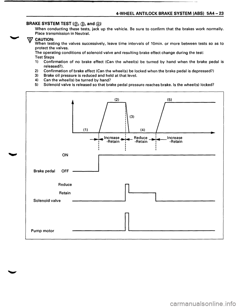
BRAKE
SYSTEM TEST (®, @, and @)
When conducting these tests, jack up the vehicle. Be sure to confirm that the brakes work normally.
Place transmission
in Neutral.
\V CAUTION: When testing the valves successively, leave time intervals of 10min. or more between tests so as to
protect the valves.
The operating conditions
of solenoid valve and resulting brake effect change during the test:
Test
Steps
1) Confirmation of no brake effect (Can the wheel(s) be turned by hand when the brake pedal is
released?).
2) Confirmation of brake effect (Can the wheel(s) be locked when the brake pedal is depressed?)
3) Brake oil pressure is reduced and held at that level.
4) Can the wheel(s) be turned by hand?
5) Solenoid valve is released so that brake pedal pressure reaches brake. Is the wheel(s) locked?
(2) (5)
I
(3)
(1) (4) I
I
..,. ;.,.. lncrea~e ..,.1.,.. Reduce I Increase ... : ... 1 -Retam 1 -Retain I -Retain I I I
I I I
I I I
I I I
ON
Brake
pedal OFF
Reduce
r
Retain
I Solenoid valve
Pump
motor ~
Page 502 of 1928
6-4 ENGINE DIAGNOSIS
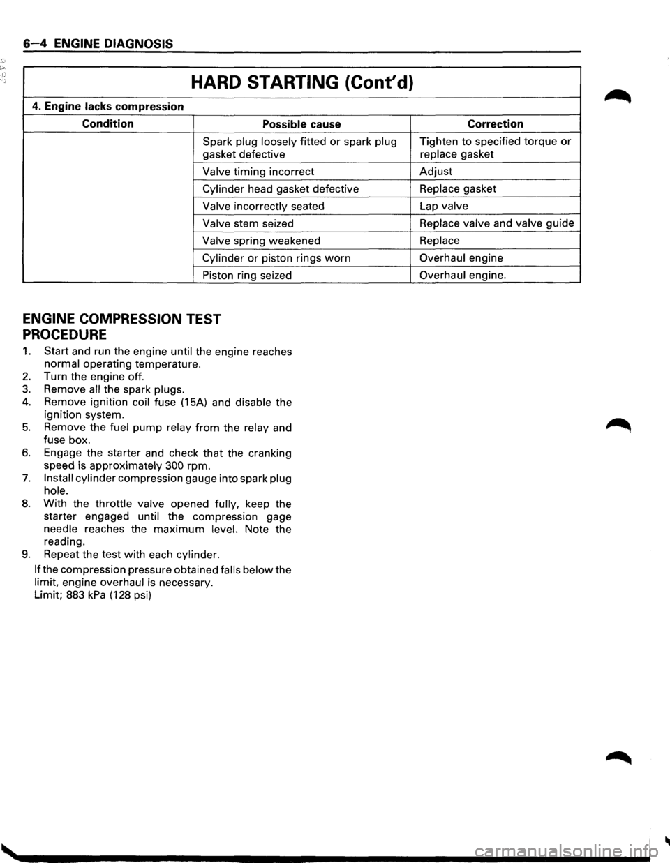
HARD STARTING (Cont'd)
4. Engine lacks compression
Condition Possible cause
Spark plug loosely fitted or spark plug
gasket defective
Valve timing incorrect
Cylinder head gasket defective
Valve incorrectly seated
Valve stem seized
Valve spring weakened
Cylinder or piston rings worn
Piston ring seized
ENGINE COMPRESSION TEST
PROCEDURE
1. Start and run the engine until the engine reaches
normal operating temperature.
2. Turn the engine off.
3. Remove all the spark plugs.
4. Remove ignition coil fuse (15A) and disable the
ignition system.
5. Remove the fuel pump relay from the relay and
fuse box.
6. Engage the starter and check that the cranking
speed is approximately
300 rpm.
7. Install cylinder compression gauge into spark plug
hole.
8. With the throttle valve opened fully, keep the
starter engaged
until the compression gage
needle reaches the
maximum level. Note the
reading.
9. Repeat the test with each cylinder.
If
the compression pressure obtained falls below the
limit, engine overhaul is necessary.
Limit; 883
kPa (128 psi) Correction
Tighten
to specified torque or
replace gasket
Adjust
Replace gasket
Lap
valve
Replace valve
and valve guide
Replace
Overhaul engine
Overhaul engine.
Page 507 of 1928
ENGINE DIAGNOSIS 6-9
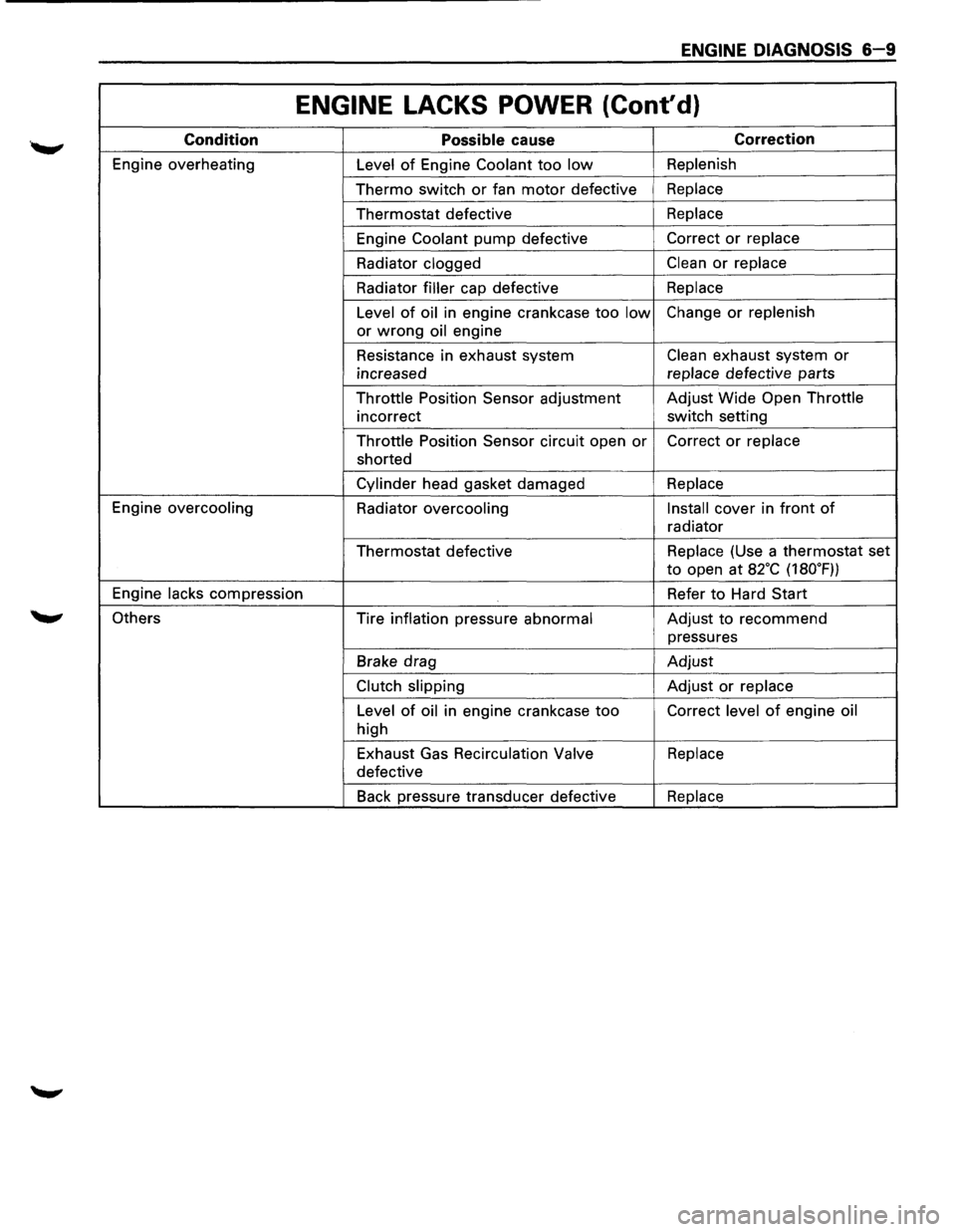
ENGINE LACKS POWER (Cont'd)
Condition Possible cause Correction
Engine overheating
Level of Engine Coolant too low Replenish
Thermo switch or fan motor defective Replace
Thermostat defective Replace
Engine
Coolant pump defective Correct or replace
Radiator clogged
Clean or replace
Radiator
filler cap defective Replace
Level
of oil in engine crankcase too low Change or replenish
or
wrong oil engine
Resistance in exhaust system
Clean exhaust system or
increased replace
defective parts
Throttle Position Sensor adjustment Adjust
Wide Open Throttle
incorrect switch setting
Throttle Position Sensor circuit open
or Correct or replace
shorted
Cylinder head gasket damaged Replace
Engine overcooling
Radiator
overcooling Install cover
in front of
radiator
Thermostat defective Replace
(Use a thermostat set
to open at a2·c (180.F))
Engine
lacks compression Refer to Hard Start
Others Tire inflation pressure
abnormal Adjust to recommend
pressures
Brake drag Adjust
Clutch slipping Adjust or replace
Level
of oil in engine crankcase too Correct level of engine oil
high
Exhaust Gas
Recirculation Valve Replace
defective
Back pressure transducer defective
Replace
Page 514 of 1928
6-16 ENGINE DIAGNOSIS
ENGINE OIL PRESSURE CHECK
1. Check for dirt, gasoline or water in the engine
oil.
a. Change the oil if dirt, gasoline, or water
are present.
b. Check the viscosity of the oil.
c. Change the oil if the viscosity is outside
the specified standard.
d. Refer to the "Maintenance and Lubrication"
section of this manual.
2. Check the engine oil level.
The level should fall somewhere between the
"ADD" and the "FULL" marks on the oil level
dipstick.
If the oil level does not reach the "ADD" mark
on the
oil level dipstick, engine oil must be
added.
3. Remove the oil pressure unit.
4. Install an oil pressure gage.
5. Start the engine and allow the engine to reach
normal operating temperature (About 80°C).
6. Measure the oil pressure.
Oil pressure should be:
7. Stop the engine.
392-550 kPa (56.9-80.4 psi)
at
3000 rpm.
8. Remove the oil pressure gage.
9. Install the oil pressure unit.
10. Start the engine and check for leaks.
m ... cw
•
Page 601 of 1928
EJ REMOVAL
Preparation: • Remove engine hood.
• Drain radiator Engine Coolant.
• Disconnect battery ground cable.
1. Air cleaner assembly
2. Radiator upper fan shroud
• Remove from radiator.
3. Radiator fan assembly
• Remove four nuts, then the radiator fan
assembly.
4. Accelerator Pedal cable
• Disconnect from throttle body and cable
bracket.
5. Canister vacuum hose
6. Vacuum booster hose
• Disconnect from common chamber.
7. Connectors
• Disconnect from Manifold Absolute Pressure,
canister Vacuum Switching
Valve (VSV),
Exhaust Gas Recirculation VSV,
Intake Air
Temperature and ground cable.
8. High tension cables
• Disconnect from cylinder head cover.
9. Ignition Control Module assembly
• Disconnect three Electronic Ignition con
nectors.
• Remove three Electronic Ignition bracket fixing
bolts, and remove Electronic Ignition assembly
with high tension cables.
10. Throttle body
• Remove four fixing bolts.
11. Vacuum hoses
• Disconnect vacuum hoses on canister VSV and
Exhaust Gas Recirculation VSV
from the
throttle body.
12. Positive Crankcase Ventilation hose
• Disconnect from common chamber.
13. Fuel Pressure Control Valve vacuum hose
• Disconnect from common chamber.
14. Evaporative Emission Canister Purge hose
• Disconnect from common chamber.
15. Exhaust Gas Recirculation assembly
16. Common chamber
• Remove six bolts, two nuts and four bracket
fixing bolts, then remove the
common
chamber.
17. Throttle body
• Disconnect Engine Coolant hose from throttle
body.
• Disconnect Idler Air Control Valve and Throttle
Position Sensor connectors.
ENGINE (V6 3.2L DOHC AND SOHC) 6A1-43
18. Fuelhoses
• Disconnect feed and return fuel hoses from fuel
pipes, and remove two bracket fixing bolts on
the cylinder head cover.
19. Fuel injector connectors
• Disconnect connectors from injectors.
• Disconnect thermo sensor connector.
20. Intake manifold
• Remove two fixing bolts and four nuts.
21. Engine Coolant manifold
• Disconnect heater hose.
• Remove four fixing bolts.
22. Power steering pump drive belt
23. Air Conditioning compressor drive belt
24. Generator drive belt
25. Power steering pump
26.
Fan pulley assembly
27. Crankshaft pulley assembly
~ • Using special tool J-8614-01, hold crankshaft
~ pulley.
•
Remove center bolt, then the pulley.
28. Oil cooler hose
• Remove two cooler hose bracket fixing bolts on
the timing
belt cover.
29. Timing belt cover
30. Pusher
\fl CAUTION:
VI The pusher prevents air from entering the oil
chamber. Its rod must always be facing upward.
31. Timing belt
\fl CAUTIONS:
VI 1) Do not bend or twist the belt, otherwise its
core
could be damaged. The belt should not
be bent at a radius less than 30mm.
2) Do not allow oil or other chemical substances
to come in contact with the belt. They will
shorten the belt life.
3) Do not attempt to pry or stretch the belt with a
screwdriver
or any other tool during
installation.
4) Store timing belt in a cool and dark place.
Never expose the
belt to direct sunlight or
heat.
32. Cylinder head cover
• Remove 11 fixing bolts, then the cylinder head
cover.
33. Power steering pump bracket
• Disconnect ground cable from bracket.
• Remove five fixing bolts, then the bracket.
34. Exhaust front pipe
35.
Level gage guide tube fixing bolt
• Remove from cylinder head.
36. Cylinder head