oil level ISUZU TROOPER 1995 Owner's Manual
[x] Cancel search | Manufacturer: ISUZU, Model Year: 1995, Model line: TROOPER, Model: ISUZU TROOPER 1995Pages: 1928
Page 602 of 1928
'.:.:.
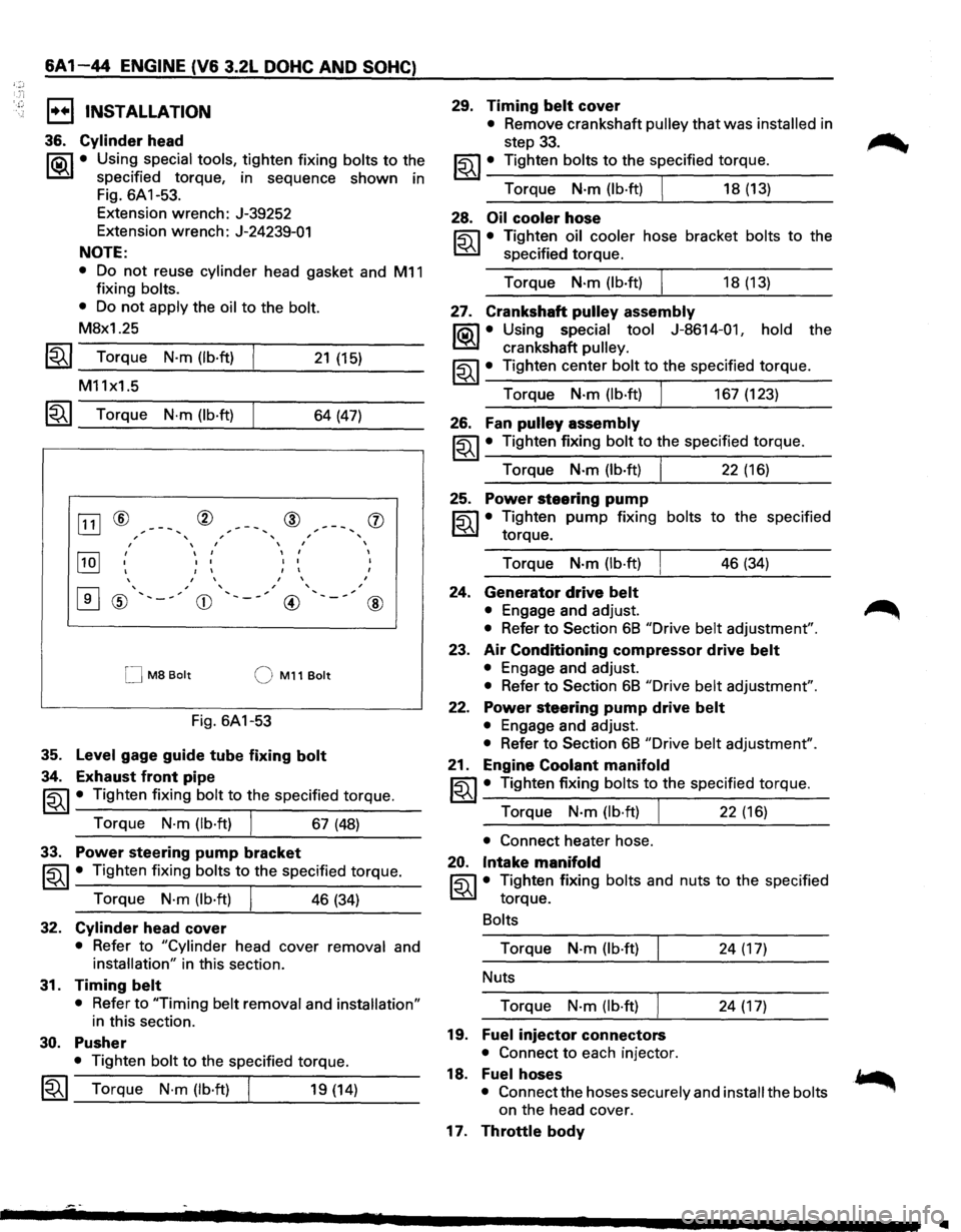
6A1-44 ENGINE (V6 3.2L DOHC AND SOHC)
1••1 INSTALLATION
36. Cylinder head
l"i:a\1 • Using special tools, tighten fixing bolts to the
~ specified torque, in sequence shown in
Fig.
6A 1-53.
Extension wrench: J-39252
Extension wrench: J-24239-01
NOTE:
• Do not reuse cylinder head gasket and M11
fixing bolts.
• Do not apply the oil to the bolt.
M8x1.25
1~1 Torque N·m (lb·ft)
M11x1.5
21 (15)
~~~ Torque N·m (lb·ft) 64 (47)
[ill ® ® @ , , , I I I
~
I
I I
I I
I I I
I I
I I I
I I
I
0
' , , ' ' , ' , ' ® '-~ CD @
M8 Bolt QM11Bolt
Fig. 6A1-53
35. Level gage guide tube fixing bolt
34. Exhaust front pipe
' '
, ,
(j)
I
I
I
@
~~~ • Tighten fixing bolt to the specified torque.
Torque
N·m (lb·ft) I 67 (48)
33. Power steering pump bracket
~~~· Tighten fixing bolts to the specified torque.
Torque
N·m (lb·ft) I 46 (34)
32. Cylinder head cover
• Refer to "Cylinder head cover removal and
installation" in this section.
31. Timing belt
• Refer to "Timing belt removal and installation"
in this section.
30. Pusher
• Tighten bolt to the specified torque.
1~1 Torque N·m (lb·ft) I 19 (14)
29. Timing belt cover
• Remove crankshaft pulley that was installed in
step
33.
~~~· Tighten bolts to the specified torque.
Torque
N·m (lb·ft) I 18 (13)
28. Oil cooler hose
~ • Tighten oil cooler hose bracket bolts to the
~ specified torque.
Torque
N·m(lb·ft) I 18(13)
27. Crankshaft pulley assembly
l"i:a\1 • Using special tool J-8614-01, hold the
~ crankshaft pulley.
~~~· Tighten center bolt to the specified torque.
Torque
N·m (lb·ft) I 167 (123)
26. Fan pulley assembly
~~~ • Tighten fixing bolt to the specified torque.
Torque
N·m (lb·ft) I 22 (16)
25. Power steering pump
~ • Tighten pump fixing bolts to the specified
~ torque.
Torque
N-m (lb·ft) 46 (34)
24. Generator drive belt
• Engage and adjust.
• Refer to Section 68 "Drive belt adjustment".
23. Air Conditioning compressor drive belt
• Engage and adjust.
• Refer to Section 68 "Drive belt adjustment".
22. Power steering pump drive belt
• Engage and adjust.
• Refer to Section 68 "Drive belt adjustment".
21. Engine Coolant manifold
~~~· Tighten fixing bolts to the specified torque.
Torque
N·m (lb·ft) J 22 (16)
• Connect heater hose.
20. Intake manifold
~ • Tighten fixing bolts and nuts to the specified
~ torque.
Bolts
Torque N-m (lb·ft) 24 (17)
Nuts
Torque
N-m (lb·ft) 24 (17)
19. Fuel injector connectors
• Connect to each injector.
18. Fuelhoses
• Connect the hoses securely and install the bolts
on the head cover.
17. Throttle body
..
Page 606 of 1928
~:· T·, ·.}:
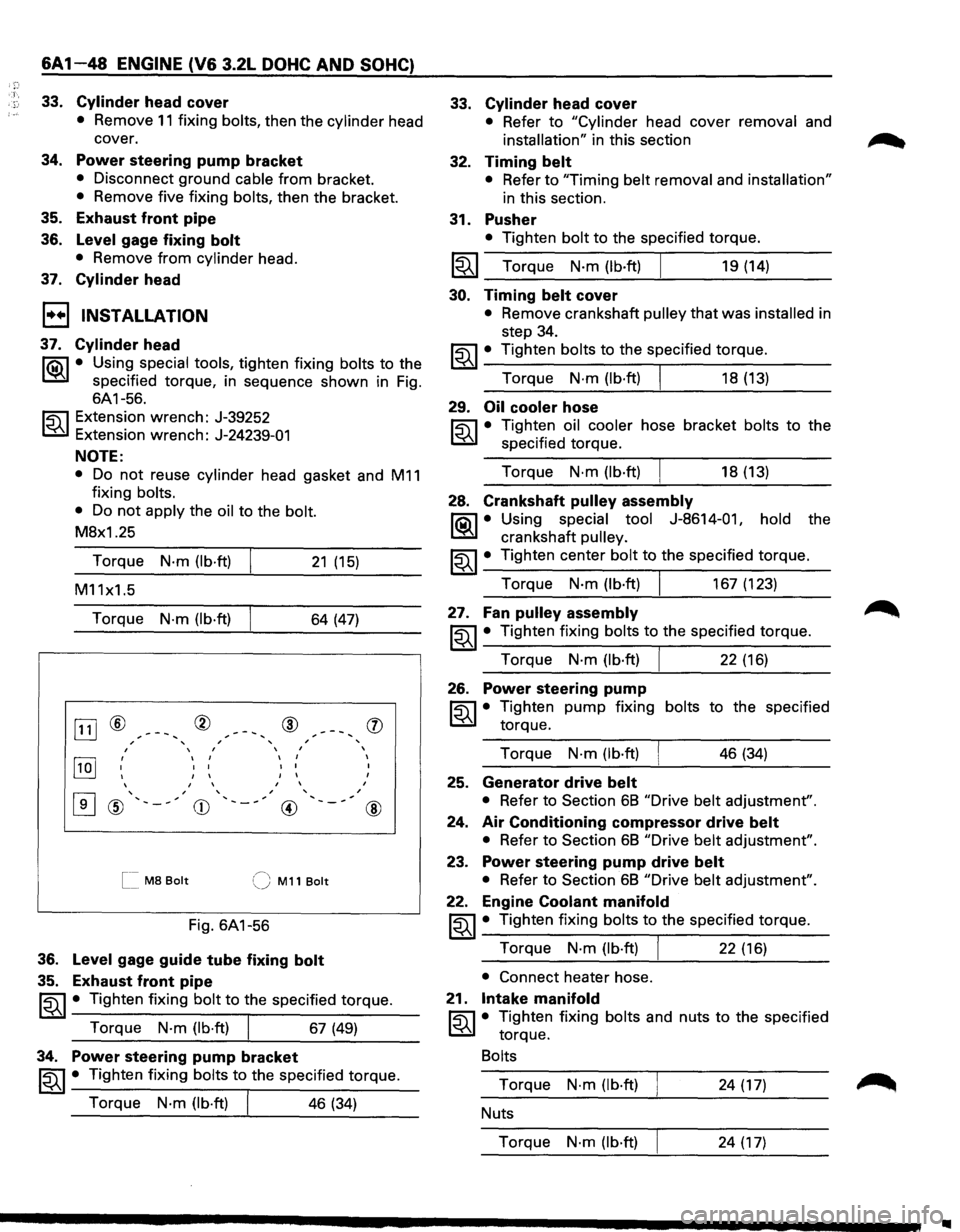
6A1-48 ENGINE (V6 3.2L DOHC AND SOHC)
33. Cylinder head cover
• Remove 11 fixing bolts, then the cylinder head
cover.
34. Power steering pump bracket
• Disconnect ground cable from bracket.
35.
• Remove five fixing bolts, then the bracket.
Exhaust front pipe
36.
37. Level gage fixing bolt
• Remove from cylinder head.
Cylinder head
1••1 INSTALLATION
37. Cylinder head
li0\1 • Using special tools, tighten fixing bolts to the
~ specified torque, in sequence shown in Fig.
6A1-56.
~ Extension wrench: J-39252
t:6.l Extension wrench: J-24239-01
NOTE:
• Do not reuse cylinder head gasket and M11
fixing bolts.
•
Do not apply the oil to the bolt.
M8x1.25
Torque
N·m (lb·ft) 21 (15)
M11x1.5
Torque
N·m (lb·ft) 64 (47)
OJ] ® ® ® , ' ' ,
, I , ,
[IQJ ' I I
I I
I I I
I I
I I I
I I
,
[I] ' , , ' @ ' ,
CD ' , , __
@
[[ M8 Bolt (J M11 Bolt
Fig.
6A1-56
36. Level gage guide tube fixing bolt
35. Exhaust front pipe
'
,
(])
I
I
I
,
@
~~~ • Tighten fixing bolt to the specified torque.
Torque
N·m (lb·ft) I 67 (49)
34. Power steering pump bracket
~~~ • Tighten fixing bolts to the specified torque.
Torque
N·m (lb·ft) I 46 (34)
33.
32.
31.
Cylinder head cover
• Refer to "Cylinder head cover removal and
installation" in this section
Timing belt
• Refer to "Timing belt removal and installation"
in this section.
Pusher
• Tighten bolt to the specified torque.
I~I __ T_o_r~qu_e __ N_·_m~(lb_·ft_)~ ______ 1_9_(1_4_) ____ _
30. Timing belt cover
• Remove crankshaft pulley that was installed in
step 34.
~~~· Tighten bolts to the specified torque.
Torque
N·m (lb·ft) I 18 (13)
29. Oil cooler hose
~ • Tighten oil cooler hose bracket bolts to the
t:6.l specified torque.
Torque
N·m (lb·ft) I 18 (13)
28. Crankshaft pulley assembly
li0\1 • Using special tool J-8614-011 hold the
~ crankshaft pulley.
~~~ • Tighten center bolt to the specified torque.
Torque
N·m (lb·ft) I 167 (123)
27. Fan pulley assembly
~~~· Tighten fixing bolts to the specified torque.
Torque
N·m (lb·ft) I 22 (16)
26. Power steering pump
~ • Tighten pump fixing bolts to the specified
t:6.l torque.
Torque
N·m (lb·ft) I 46 (34)
25. Generator drive belt
• Refer to Section 68 "Drive belt adjustment".
24.
Air Conditioning compressor drive belt
• Refer to Section 68 "Drive belt adjustment".
23. Power steering pump drive belt
• Refer to Section 68 "Drive belt adjustment".
22. Engine Coolant manifold
~~~· Tighten fixing bolts to the specified torque.
Torque
N·m (lb·ft) I 22 (16)
• Connect heater hose.
21.
Intake manifold
~ • Tighten fixing bolts and nuts to the specified
t:6.l torque.
Bolts
Torque N·m (lb·ft) 24 (17)
Nuts
Torque
N·m (lb·ft) 24 (17)
..
Page 608 of 1928
6A1 50 ENGINE (V6 3.2L DOHC AND SOHC)
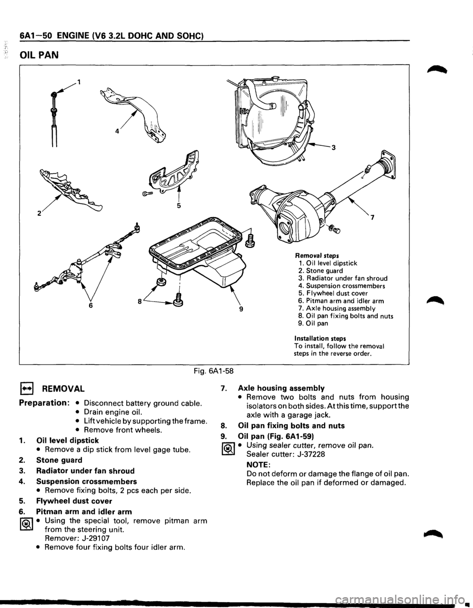
OIL PAN
1
6
Removal steps 1. Oil level dipstick
2. Stone guard
3. Radiator under fan shroud
4. Suspension crossmembers
5.
Flywheel dust cover
6. Pitman arm and
idler arm
7. Axle housing assembly 8. Oil pan fixing bolts and nuts
9. Oil pan
Installation steps
To install, follow the removal steps in the reverse order.
Fig. 6A1-58
1••1 REMOVAL
Preparation: • Disconnect battery ground cable.
•
Drain engine oil.
•
Lift vehicle by supporting the frame.
• Remove front wheels.
1. Oil level dipstick
• Remove a dip stick from level gage tube.
2. Stone guard
3. Radiator under fan shroud
4.
5.
6.
Suspension crossmembers
• Remove fixing bolts, 2 pes each per side.
Flywheel dust cover
Pitman arm and
idler arm
~·
Using the special tool, remove pitman arm
from the steering unit.
Remover: J-291
07
• Remove four fixing bolts four idler arm.
7. Axle housing assembly
• Remove two bolts and nuts from housing
isolators on both sides. Atthis time, supportthe
axle with a garage jack.
8. Oil pan fixing bolts and nuts
9. Oil pan (Fig. 6A1-59)
fiOil • Using sealer cutter, remove oil pan.
~ Sealer cutter: J-37228
NOTE:
Do not deform or damage the flange of oil pan.
Replace the oil pan if deformed or damaged.
•
Page 631 of 1928
Mixing ratio(%) 0 10 20 30 40 50
~
' -10
'
1
' -30
~ -40
In case of 8.5 lit total cooling system capacity
Mixing Anti-freeze
Water: solution: ratio (%) lit. (U.S. gal) lit. (U.S. gal.)
0 0 0
8.5 (2.2) 10 0.9 (0.3) 7.6 (2.0) 15
1.3 (0.4) 7.2 (1.9) 20 1.7 (0.5) 6.8 (1.8)
25 2.1 (0.6) 6.4 (1.7) 30 2.6 (0.7) 5.9 (1.6)
35 3.0 (0.8) 5.5
(1.5) 40 3.4 (0.9) 5.1 (1.3)
45 3.8 (1.0) 4.7 (1.2) 50 4.3 (1.1)
4.2 (1.1)
Fig. 68-5
ENGINE COOLING 68-3
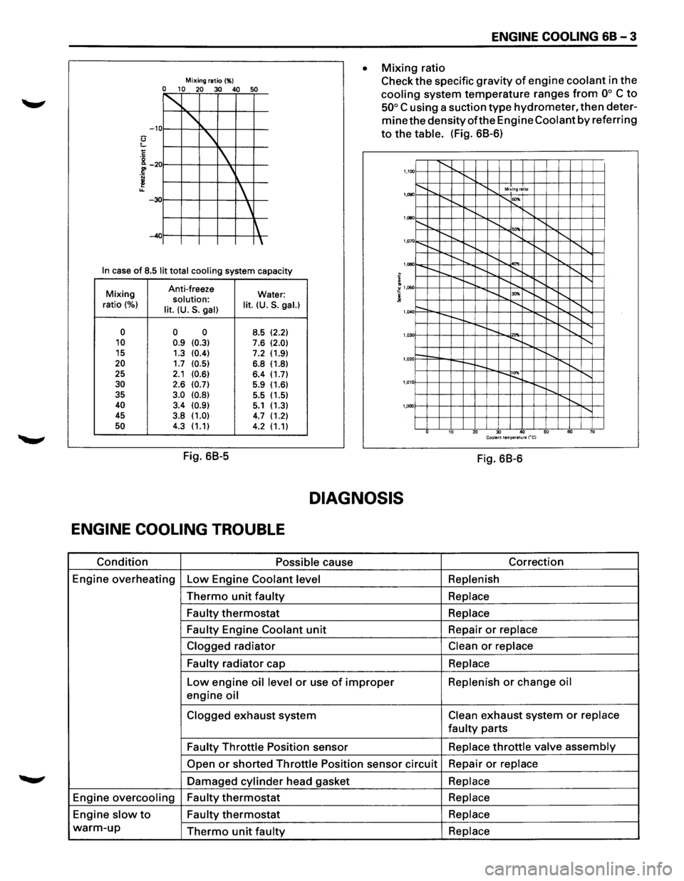
• Mixing ratio
Check
the specific gravity of engine coolant in the
cooling system temperature ranges from oo C to
50° C using a suction type hydrometer, then deter
mine the densityofthe Engine Coolant by referring
to the table. (Fig. 68-6)
1,100 1'-........ ........ ...... .............. Mixing ratio
~"""--r-... 1'-""' 1,1)90
........ ...... ........ ........ .......... '
1,000
'"" 1,07 o......_ 1'-........ I'-.......... I"-........ .......
I"-........ ..........
................. I"-........
'
1,080
....... I"-........ ~ ........ ......
........ "'" ~"""--r--..... 1,050
r-. ........ ~ .......... ......
---
........ ........ 1,040
r-.... !'--.. 1'-0 '"" ~"""--1'-.... ........ 1,03
1--....... ........ r--~ ........
'
1,020
....... ~ 1'-0 ~"""---.... 1,01
...... ,
'
1,000
10 20 30 40 50 60 70 Coolant temperature ("C)
Fig. 68-6
DIAGNOSIS
ENGINE COOLING TROUBLE
Condition Possible cause Correction
Engine
overheating Low Engine Coolant level Replenish
Thermo unit faulty Replace
Faulty
thermostat Replace
Faulty
Engine Coolant unit Repair or replace
Clogged
radiator Clean or replace
Faulty
radiator cap Replace
Low engine oil level or use of improper Replenish or change oil
engine oil
Clogged exhaust system Clean exhaust system or replace
faulty parts
Faulty Throttle Position sensor Replace throttle valve assembly
Open or shorted Throttle Position sensor circuit Repair or replace
Damaged cylinder head gasket Replace
Engine overcooling Faulty thermostat Replace
Engine slow to Faulty thermostat Replace
warm-up Thermo unit faulty Replace
Page 632 of 1928
68 - 4 ENGINE COOLING
ON-VEHICLE SERVICE
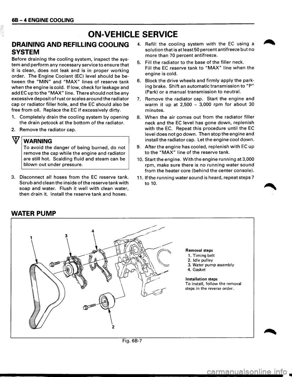
DRAINING AND REFILLING COOLING
SYSTEM
Before draining the cooling system, inspect the sys
tem and perform any necessary service to ensure that
it is clean, does not leak and is in proper working
order. The Engine Coolant (EC) level should be be
tween the "MIN" and "MAX" lines of reserve tank
when the engine is cold. If low, check for leakage and
add
EC up to the "MAX" line. There should not be any
excessive deposit of rust or scales around the radiator
cap
or radiator filler hole, and the EC should also be
free
from oil. Replace the EC if excessively dirty.
1. Completely drain the cooling system by opening
the drain petcock at the bottom of the radiator.
2. Remove the radiator cap.
W WARNING
To avoid the danger of being burned, do not
remove the cap while the engine and radiator
are still hot. Scalding fluid and steam can be
blown out under pressure.
3. Disconnect all hoses from the EC reserve tank.
Scrub and clean the inside of the reserve tank with
soap and water. Flush it well with clean water,
then drain it. Install the reserve tank and hoses.
WATER PUMP
3
j
2
4. Refill the cooling system with the EC using a
solution that is at least 50 percent antifreeze but no
more than 70 percent antifreeze.
5. Fill the radiator to the base of the filler neck.
Fill the EC reserve tank to "MAX" line when the
engine is cold.
6. Block the drive wheels and firmly apply the park
ing brake.
Shift an automatic transmission to "P"
(Park) or a manual transmission to neutral.
7. Remove the radiator cap. Start the engine and
warm it up at 2,500 -3,000 rpm for about 30
minutes.
8. When the air comes out from the radiator filler
neck and the EC level has gone down, replenish
with the EC. Repeat this procedure until the EC
level does not go down. Then stop the engine and
install the radiator cap. Let the engine cool down.
9. After the engine has cooled, replenish with EC up
to the "MAX" line of the reserve tank.
10. Start the engine. With the engine running at 3,000
rpm, make sure there is no running water sound
from the heater core (behind the center console).
11. If the running water sound is heard, repeat steps 7
to 10.
Removal steps
1. Timing
belt 2. Idle pulley 3. Water pump assembly
4. Gasket
Installation steps To install, follow the removal steps in the reverse order.
Fig. 6B-7
•
Page 637 of 1928
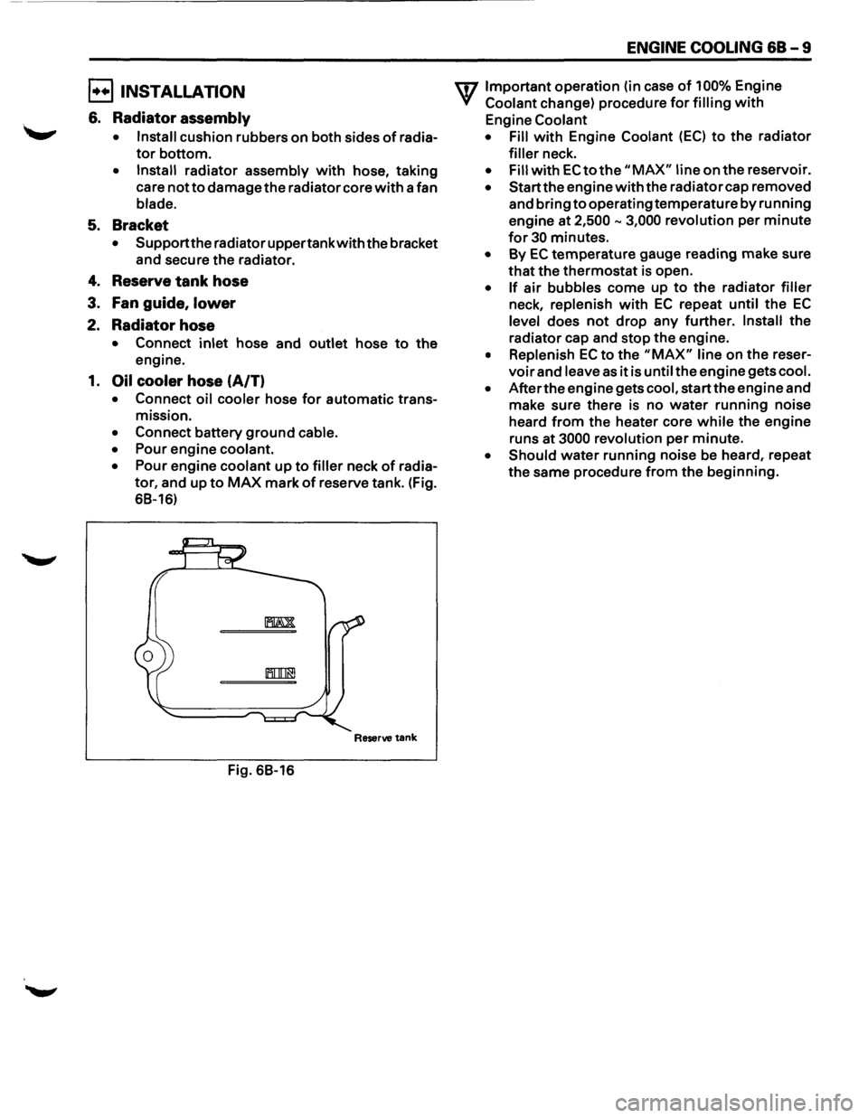
E!) INSTALLATION
6. Radiator assembly
• Install cushion rubbers on both sides of radia
tor bottom.
• Install radiator assembly with hose, taking
care
not to damage the radiator core with a fan
blade.
5. Bracket
• Support the radiator uppertankwith the bracket
and secure the radiator.
4. Reserve tank hose
3. Fan guide, lower
2. Radiator hose
• Connect inlet hose and outlet hose to the
engine.
1. Oil cooler hose (A/T)
• Connect oil cooler hose for automatic trans-
mission.
• Connect battery ground cable.
• Pour engine coolant.
• Pour engine coolant up to filler neck of radia
tor, and up to MAX mark of reserve tank. (Fig.
68-16)
Reserve tank
Fig. 68-16
ENGINE COOLING 68-9
U7 Important operation (in case of 100% Engine
V Coolant change) procedure for filling with
Engine Coolant
• Fill
with Engine Coolant (EC) to the radiator
filler neck.
• Fill with EC to the "MAX" line on the reservoir.
• Start the engine with the radiator cap removed
and bring
to operating temperature by running
engine at
2,500-3,000 revolution per minute
for 30 minutes.
• By EC temperature gauge reading make sure
that the thermostat is open.
• If air bubbles come up to the radiator filler
neck, replenish with EC repeat until the EC
level does not drop any further. Install the
radiator cap and stop the engine.
• Replenish EC to the "MAX" line on the reser
voir and leave as it is until the engine gets cool.
• After the engine gets cool, start the engine and
make sure there is no
water running noise
heard
from the heater core while the engine
runs
at 3000 revolution per minute.
• Should water running noise be heard, repeat
the same procedure from the beginning.
Page 703 of 1928
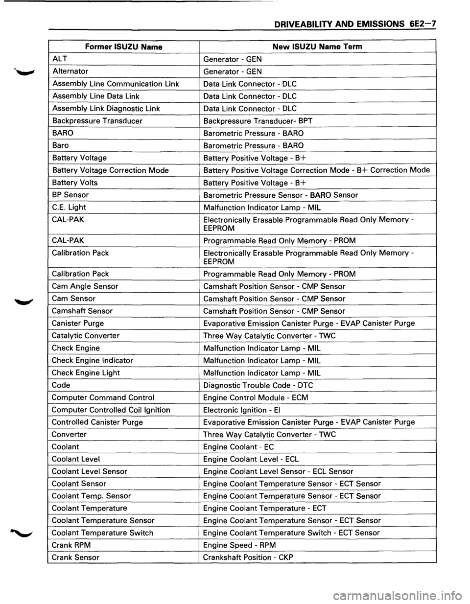
DRIVEABILITY AND EMISSIONS 6E2-7
Former ISUZU Name New ISUZU Name Term
ALT Generator -GEN
Alternator
Generator -GEN
Assembly Line Communication Link
Data Link Connector -DLC
Assembly Line Data Link
Data Link Connector -DLC
Assembly Link Diagnostic Link
Data Link Connector -DLC
Backpressure Transducer
Backpressure Transducer-BPT
BARO Barometric Pressure -BARO
Baro
Barometric Pressure -BARO
Battery Voltage
Battery Positive Voltage-B+
Battery Voltage Correction Mode Battery Positive Voltage Correction Mode -B+ Correction Mode
Battery Volts
Battery
Positive Voltage-B+
BP Sensor Barometric Pressure Sensor -BARO Sensor
C.E. Light
Malfunction Indicator Lamp -MIL
CAL-PAK Electronically
Erasable Programmable Read Only Memory -
EEPROM
CAL-PAK
Programmable Read Only Memory -PROM
Calibration Pack Electronically Erasable Programmable Read Only Memory -
EEPROM
Calibration Pack
Programmable Read Only Memory-PROM
Cam Angle Sensor Camshaft Position Sensor -CMP Sensor
Cam Sensor Camshaft Position Sensor -CMP Sensor
Camshaft Sensor Camshaft Position Sensor -CMP Sensor
Canister Purge Evaporative Emission Canister Purge-EVAP Canister Purge
Catalytic Converter
Three Way Catalytic Converter-TWC
Check Engine
Malfunction
Indicator Lamp -MIL
Check Engine Indicator Malfunction Indicator Lamp -MIL
Check Engine Light
Malfunction Indicator Lamp-MIL
Code Diagnostic Trouble Code -DTC
Computer Command Control Engine Control Module -ECM
Computer Controlled Coil Ignition Electronic Ignition -El
Controlled Canister Purge Evaporative Emission Canister Purge-EVAP Canister Purge
Converter Three Way Catalytic Converter -TWC
Coolant Engine Coolant -EC
Coolant Level
Engine Coolant Level -ECL
Coolant Level Sensor Engine Coolant Level Sensor -ECL Sensor
Coolant Sensor Engine Coolant Temperature Sensor -ECT Sensor
Coolant Temp. Sensor Engine Coolant Temperature Sensor-ECT Sensor
Coolant Temperature Engine Coolant Temperature -ECT
Coolant Temperature Sensor Engine Coolant Temperature Sensor-ECT Sensor
Coolant Temperature Switch Engine Coolant Temperature Switch -ECT Sensor
Crank RPM Engine Speed -RPM
Crank Sensor Crankshaft Position-CKP
Page 792 of 1928
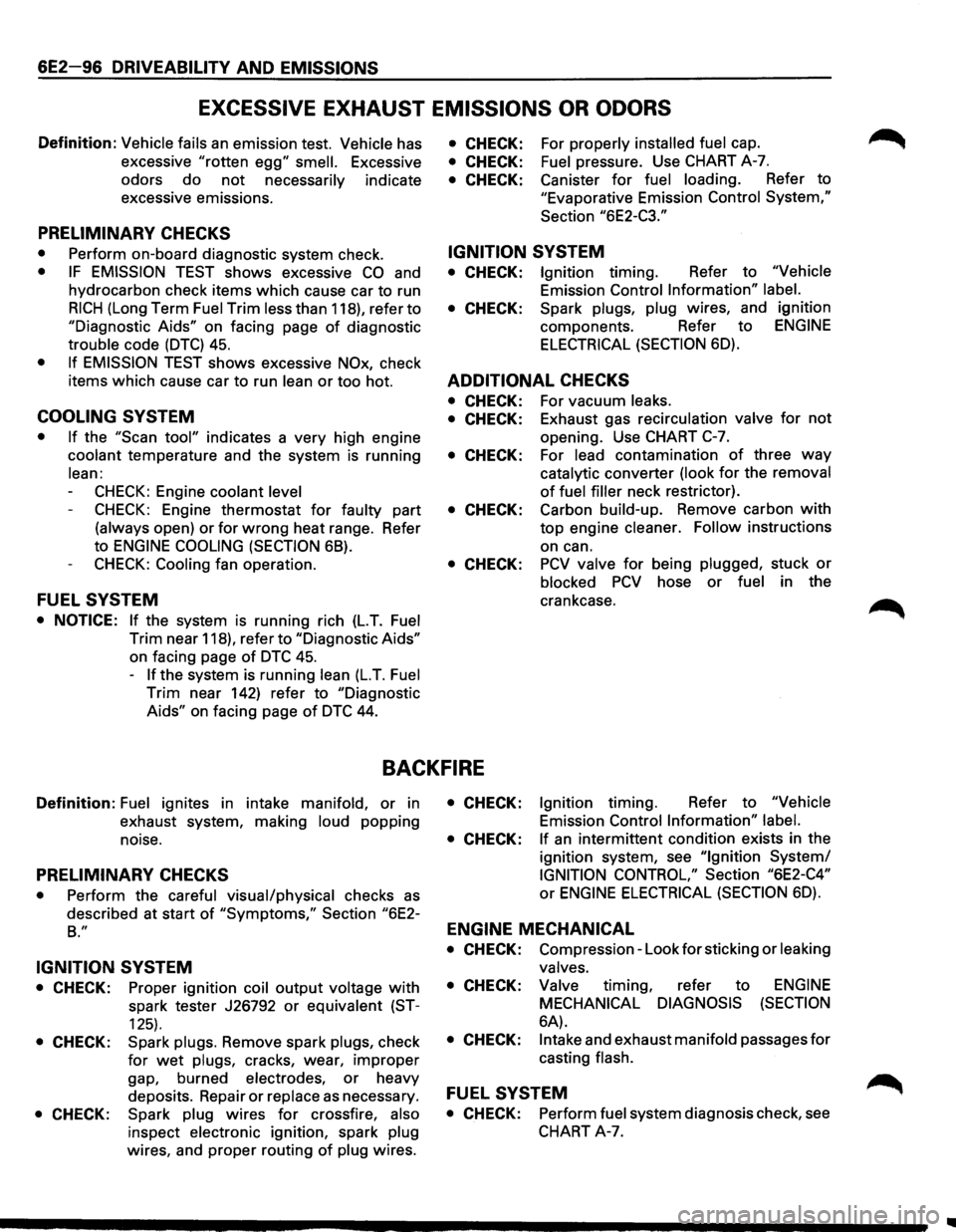
6E2-96 DRIVEABILITY AND EMISSIONS
EXCESSIVE EXHAUST EMISSIONS OR ODORS
Definition: Vehicle fails an emission test. Vehicle has
excessive
"rotten egg" smell. Excessive
odors
do not necessarily indicate
excessive emissions.
PRELIMINARY CHECKS
• Perform on-board diagnostic system check.
• IF EMISSION TEST shows excessive CO and
hydrocarbon check items which cause car to run
RICH (Long Term Fuel Trim less than 118), refer to
"Diagnostic Aids" on facing page of diagnostic
trouble code (DTC) 45.
• If EMISSION TEST shows excessive NOx, check
items which cause car
to run lean or too hot.
COOLING SYSTEM
• If the "Scan tool" indicates a very high engine
coolant temperature and the system is running
lean:
CHECK: Engine coolant level
CHECK: Engine thermostat for faulty part
(always open) or for wrong heat range. Refer
to
ENGINE COOLING (SECTION 68).
CHECK: Cooling fan operation.
FUEL SYSTEM
• NOTICE: If the system is running rich (L.T. Fuel
Trim near 118), refer to "Diagnostic Aids"
on facing page
of DTC 45.
-
If the system is running lean (L.T. Fuel
Trim near 142) refer to "Diagnostic
Aids" on facing page of DTC 44.
• CHECK: For properly installed fuel cap.
• CHECK: Fuel pressure. Use CHART A-7.
• CHECK: Canister for fuel loading. Refer to
"Evaporative Emission Control System,"
Section
"6E2-C3."
IGNITION SYSTEM
• CHECK: Ignition timing. Refer to "Vehicle
Emission Control Information" label.
• CHECK: Spark plugs, plug wires, and ignition
components. Refer to
ENGINE
ELECTRICAL (SECTION 6D).
ADDITIONAL CHECKS
• CHECK: For vacuum leaks.
• CHECK: Exhaust gas recirculation valve for not
opening. Use CHART C-7.
• CHECK: For lead contamination of three way
catalytic converter (look for the removal
of fuel filler neck restrictor).
• CHECK: Carbon build-up. Remove carbon with
top engine cleaner. Follow instructions
on can.
• CHECK: PCV valve for being plugged, stuck or
blocked PCV hose or fuel in the
crankcase.
BACKFIRE
Definition: Fuel ignites in intake manifold, or in
exhaust system, making
loud popping
noise.
PRELIMINARY CHECKS
• Perform the careful visual/physical checks as
described at start of "Symptoms," Section "6E2-
B."
IGNITION SYSTEM
• CHECK: Proper ignition coil output voltage with
spark tester J26792 or equivalent (ST-
125).
• CHECK: Spark plugs. Remove spark plugs, check
for
wet plugs, cracks, wear, improper
gap, burned
electrodes, or heavy
deposits. Repair
or replace as necessary.
• CHECK: Spark plug wires for crossfire, also
inspect electronic ignition, spark plug
wires, and proper routing of plug wires.
• CHECK: Ignition timing. Refer to "Vehicle
Emission Control Information" label.
• CHECK: If an intermittent condition exists in the
ignition system, see
"Ignition System/
IGNITION CONTROL," Section "6E2-C4"
or ENGINE ELECTRICAL (SECTION 6D).
ENGINE MECHANICAL
• CHECK: Compression- Look for sticking or leaking
valves.
• CHECK: Valve timing, refer to ENGINE
MECHANICAL DIAGNOSIS (SECTION
6A).
• CHECK: Intake and exhaust manifold passages for
casting
flash.
FUEL SYSTEM
• CHECK: Perform fuel system diagnosis check, see
CHART A-7.
Page 892 of 1928
7 A-20 AUTOMATIC TRANSMISSION (4L30-E)
CHECKING TRANSMISSION FLUID
LEVEL AND CONDITION
Checking fluid level and condition (color and odor)
at
regular intervals will provide early diagnosis
information about the transmission. This inform
ation may be used to correct a condition that, if not
detected early, could result in major transmission
repairs.
IMPORTANT: When new, automatic transmission
fluid is red in color. As the vehicle is driven, the
transmission
fluid will begin to look darker in color.
The
color may eventually appear light brown.
A DARK
brown color with burnt odor may indicate
excessive
fluid deterioration and signal a need for
fluid change.
FLUID LEVEL
When adding
or changing fluid, use only DEXRON
®-Ill.
Refer to the Maintenance and Lubrication (Section 0
of this manual) for maintenance information and
servicing
interval.
\f CAUTION: DO NOT OVERFILL
Overfilling will cause foaming, loss ~f fluid,
abnormal shifting and possible damage to
the transmission.
1. Start engine and drive vehicle until normal AfT
oil operating temperature is reached:
NOTE: The automatic transmission fluid level
must be checked with the vehicle at normal
A/T oil operating temperature: 75 TO 85°C
(167 TO 185°F) MEASURED WITH TECH1 SCAN
TOOL.
Temperature will greatly affect transmission
fluid level.
If the vehicle is not at normal AfT oil operating
temperature and the proper checking
procedures are
not followed, the result could
be a false reading of the fluid level indicator
and
an incorrect adjustment of the fluid level.
2. Park vehicle on level ground.
3. Move gear selector to "Park".
4. Apply parking brake and block wheels.
5. Allow vehicle to idle for 3 minutes with all
accessories turned off.
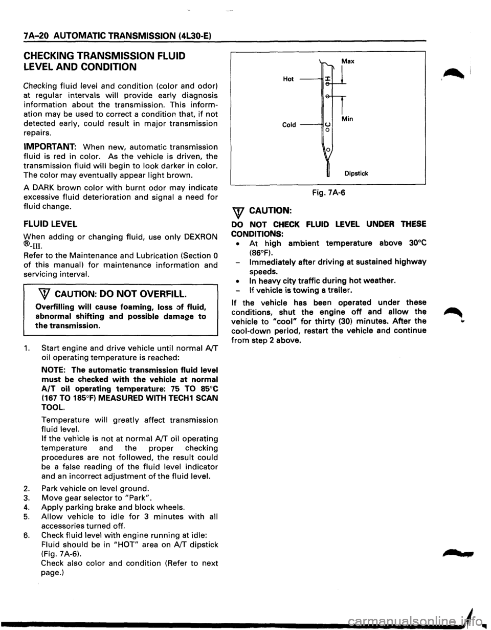
6. Check fluid level with engine running at idle:
Fluid should
be in "HOT" area on AfT dipstick
(Fig. 7A-6).
Check also color and condition (Refer to next
page.)
Hot
Cold ---IIU 0
0
Min
Dipstick
Fig. 7A-6
\f CAUTION:
DO NOT CHECK FLUID LEVEL UNDER THESE
CONDITIONS: •
At high ambient temperature above 30°C
(86°F).
Immediately after driving at sustained highway
speeds.
• In heavy city traffic during hot weather.
If vehicle is towing a trailer.
If the vehicle has been operated under these
conditions,
shut the engine off and allow the
vehicle to "cool" for thirty (30) minutes. After the
cool-down period, restart the vehicle and continue
from step 2 above.
'~I
......
Page 908 of 1928
7 A-36 AUTOMATIC TRANSMISSION (4L30-E)
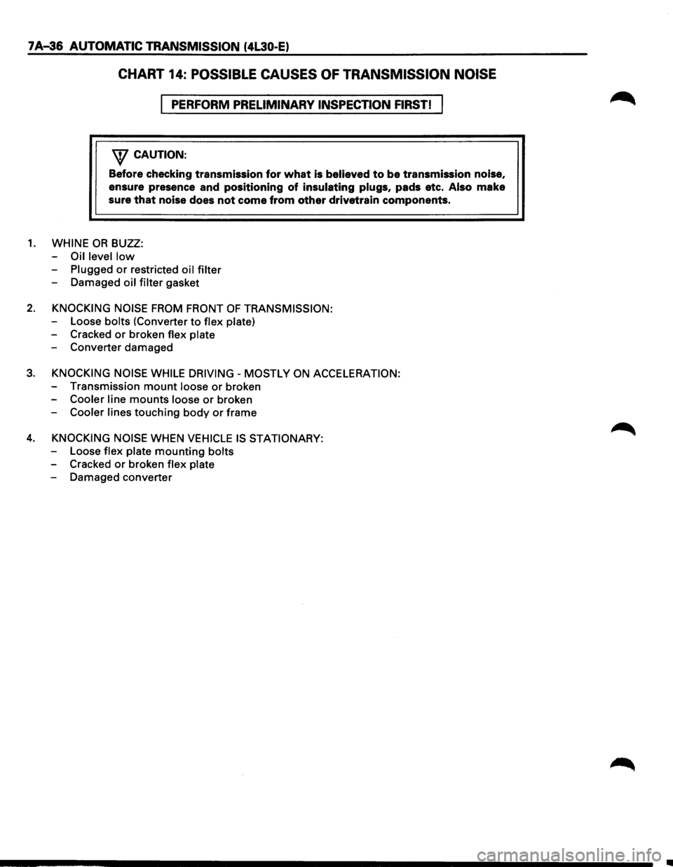
CHART 14: POSSIBLE CAUSES OF TRANSMISSION NOISE
PERFORM PRELIMINARY INSPECTION FIRST!
'\f CAUTION:
Before checking transmission for what is believed to be transmission noise,
ensure presence and
positioning of insulating plugs, pads etc. Also make
sure
that noise does not come from other drivetrain components.
1. WHINE OR BUZZ:
-
Oil level low
-Plugged or restricted oil filter
- Damaged oil filter gasket
2. KNOCKING NOISE FROM FRONT OF TRANSMISSION:
-Loose bolts (Converter to flex plate)
- Cracked or broken flex plate
-Converterdamaged
3. KNOCKING NOISE WHILE DRIVING- MOSTLY ON ACCELERATION:
-Transmission mount loose or broken
-
Cooler line mounts loose or broken
-
Cooler lines touching body or frame
4. KNOCKING NOISE WHEN VEHICLE IS STATIONARY:
-Loose flex plate mounting bolts
-Cracked or broken flex plate
-Damaged converter
II