check oil ISUZU TROOPER 1995 Service Manual
[x] Cancel search | Manufacturer: ISUZU, Model Year: 1995, Model line: TROOPER, Model: ISUZU TROOPER 1995Pages: 1928
Page 544 of 1928
6A-28 GENERAL ENGINE MECHANICAL
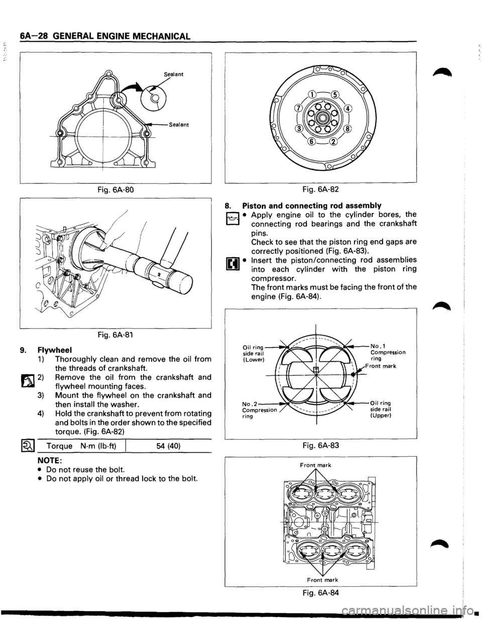
Fig. 6A-80
/
Fig. 6A-81
9. Flywheel
1) Thoroughly clean and remove the oil from
the threads
of crankshaft.
1!t1 2) Remove the oil from the crankshaft and
LQI flywheel mounting faces.
3) Mount the flywheel on the crankshaft and
then
install the washer.
4) Hold the crankshaft to prevent from rotating
and
bolts in the order shown to the specified
torque. (Fig. 6A-82)
~~~ Torque N·m (lb·ft) I ___ ___,_ ___ _ 54 (40)
NOTE:
• Do not reuse the bolt.
•
Do not apply oil or thread lock to the bolt.
Fig. 6A-82
8. Piston and connecting rod assembly
D • Apply engine oil to the cylinder bores, the
l:J connecting rod bearings and the crankshaft
pins. Check to see that the piston ring end gaps are
correctly positioned (Fig. 6A-83).
Insert the piston/connecting rod assemblies
into each cylinder with the piston ring
compressor. The
front marks must be facing the front of the
engine (Fig. 6A-84).
Oil ring ---~====-~::F::::::.===~~t---No. 1
side rail Compression (Lower) ring Front mark
No .2--~~:::::=:e!::::!-;::::!!;~~·-Oil ring
Compression side rail ring (Upper)
Fig. 6A-83
Front mark
Front mark
Fig. 6A-84
•
Page 545 of 1928
1£41• Match the numbered caps with the numbers on
the connecting rods.
Align the punched marks
on the connecting rods and caps.
1'l:::r.1• Apply engine oil to the threads and seating
faces
of the nuts.
• Tighten the nuts
~~~ Torque N·m (lb·ft) 54 (40)
7.
After tightening the cap nuts, check to see that
the crankshaft rotates smoothly.
Oil gallery
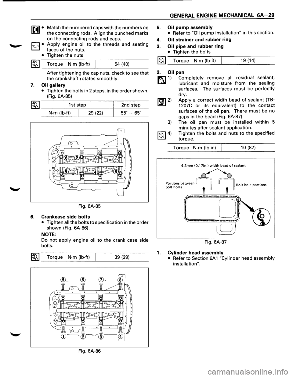
• Tighten the bolts in 2 steps, in the order shown.
(Fig. 6A-85)
1~1 _________ 1_s_t,s_te~p ________ ~ __ 2_n_d __ st_e~p---
N·m (lb·ft) 29 (22) 55° -65°
Fig. 6A-85
6. Crankcase side bolts
• Tighten all the bolts to specification in the order
shown (Fig. 6A-86).
NOTE:
Do not apply engine oil to the crank case side
bolts.
~~~ Torque N·m (lb·ft) 39 (29)
Fig. 6A-86
5.
4.
3.
GENERAL ENGINE MECHANICAL 6A-29
Oil pump assembly
• Refer to "Oil pump installation" in this section.
Oil strainer and rubber ring
Oil pipe and rubber ring
• Tighten the bolts
I~I_T_o_rq...:....u_e_N_·_m_(:.._lb_·ft....:.)---!. ___ 1_9 _(1_4_) __ _
2. Oil pan
m 1) Completely remove all residual sealant,
~ lubricant and moisture from the sealing
surfaces. The surfaces must be perfectly
dry.
~~~2) Apply a correct width bead of sealant (TB-
1207C or its equivalent) to the contact
surfaces
of the oil pan. There must be no
gaps in the bead (Fig. 6A-87).
3) The oil pan must be installed within 5
minutes after
sealant application.
~~~4) Tighten the bolts and nuts to the specified
torque.
Torque
N-m (lb-in) 10 (87)
D
Fig. 6A-87
1. Cylinder head assembly
• Refer to Section 6A
1 "Cylinder head assembly
installation".
Page 549 of 1928
3. Insert the new pin into the piston and rotate
it.
If the pin rotates smoothly with no
backlash, the clearance is normal. If there is
backlash or roughness, measure the
clearance. If the clearance exceeds the
specified
limit, the piston must be replaced.
mm (in)
Standard Limit
Clearance 0.007-0.020
0.040
(0.0003-0.0008) (0.0016)
Connecting rods
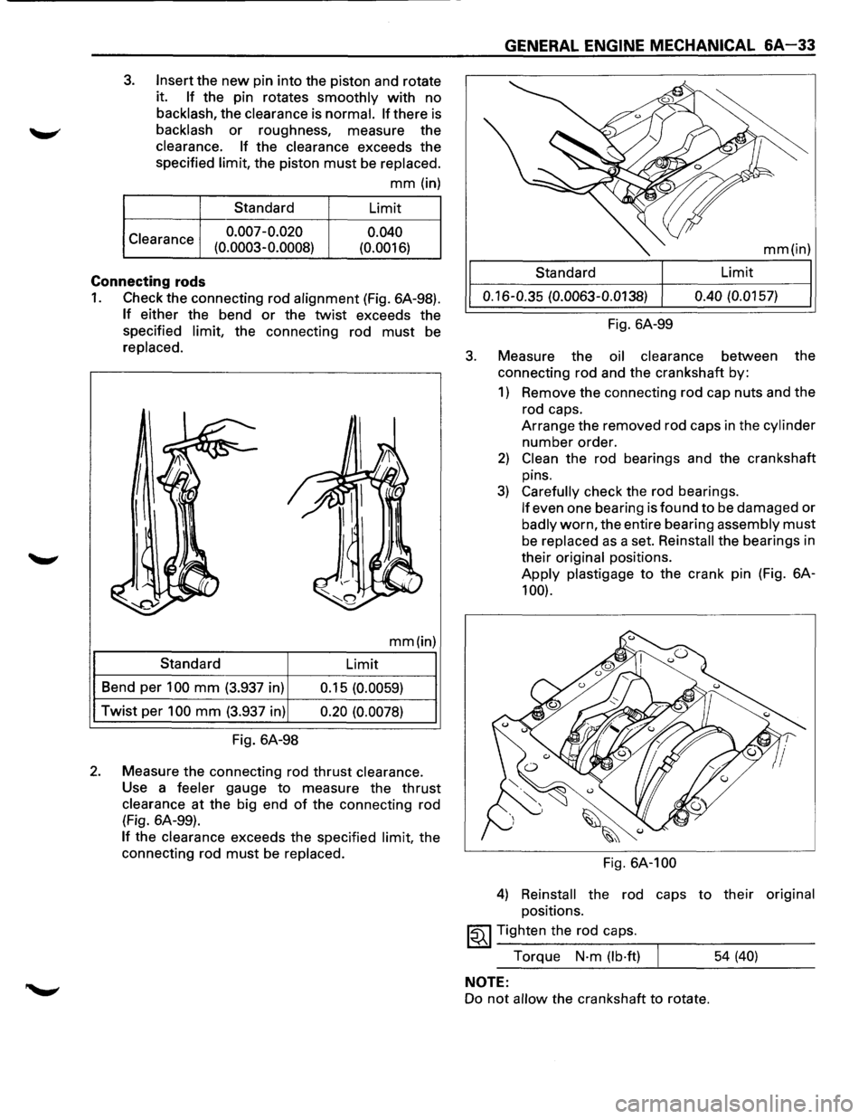
1. Check the connecting rod alignment (Fig. 6A-98).
If either the bend or the twist exceeds the
specified
limit, the connecting rod must be
replaced.
mm(in)
Standard
Limit
Bend per
100 mm (3.937 in)
0.15 (0.0059)
Twist per 100 mm (3.937 in) 0.20 (0.0078)
Fig. 6A-98
2. Measure the connecting rod thrust clearance.
Use a feeler gauge to measure the thrust
clearance at the big end of the connecting rod
(Fig. 6A-99).
If the clearance exceeds the specified limit, the
connecting rod
must be replaced.
3.
GENERAL ENGINE MECHANICAL 6A-33
mm(in)
Standard Limit
0.16-0.35
(0.0063-0.0138) 0.40
(0.0157)
Fig. 6A-99
Measure the
oil clearance between the
connecting rod and the crankshaft by:
1) Remove the connecting rod cap nuts and the
rod caps.
Arrange the removed rod caps in the
cylinder
number order.
2) Clean the rod bearings and the crankshaft
pins.
3) Carefully check the rod bearings.
If even one bearing is found to be damaged or
badly worn, the entire bearing assembly must
be replaced as a set. Reinstall the bearings in
their
original positions.
Apply plastigage to the crank pin (Fig. 6A-
100).
Fig. 6A-100
4) Reinstall the rod caps to their original
positions.
~~~ Tighten the rod caps.
Torque
N·m (lb·ft) 54 (40)
NOTE:
Do not allow the crankshaft to rotate.
Page 551 of 1928
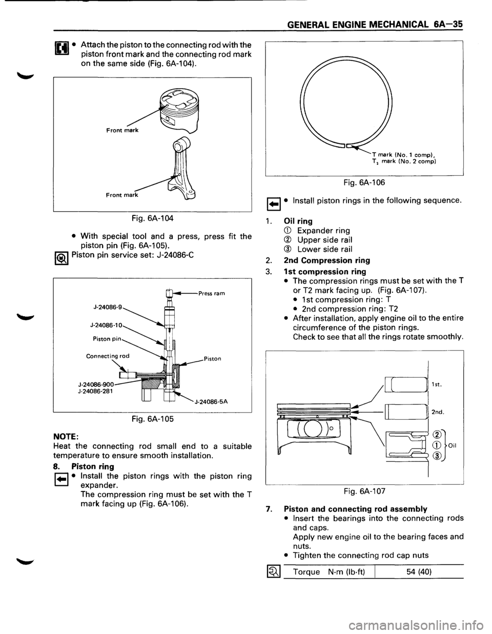
Attach the piston to the connecting rod with the
piston
front mark and the connecting rod mark
on the same side (Fig. 6A-104).
Fig. 6A-104
• With special tool and a press, press fit the
piston pin (Fig. 6A-105).
1®1 Piston pin service set: J-24086-C
NOTE:
J-24086-900 J-24086-281
Fig. 6A-105
J-24086-5A
Heat the connecting rod small end to a suitable
temperature to ensure smooth installation.
8. Piston ring
r=1 • Install the piston rings with the piston ring
1=.1 expander.
The compression ring
must be set with the T
mark facing up (Fig. 6A-106).
GENERAL ENGINE MECHANICAL &A-35
T mark (No.1 comp), T2 mark (No.2 comp)
Fig. 6A-106
1 ... 1• Install piston rings in the following sequence.
1. Oil ring
CD Expander ring
® Upper side rail
® Lower side rail
2. 2nd Compression ring
3. 1st compression ring
• The compression rings must be set with the T
or
T2 mark facing up. (Fig. 6A-1 07).
•
1st compression ring: T
• 2nd compression ring: T2
• After installation, apply engine oil to the entire
circumference
of the piston rings.
Check to see that all the rings rotate smoothly.
Fig. 6A-107
7. Piston and connecting rod assembly
• Insert
the bearings into the connecting rods
and caps.
Apply new engine oil to the bearing faces and
nuts.
• Tighten the connecting rod cap nuts
1~1 Torque N·m (lb·ft) 54 (40)
Page 555 of 1928
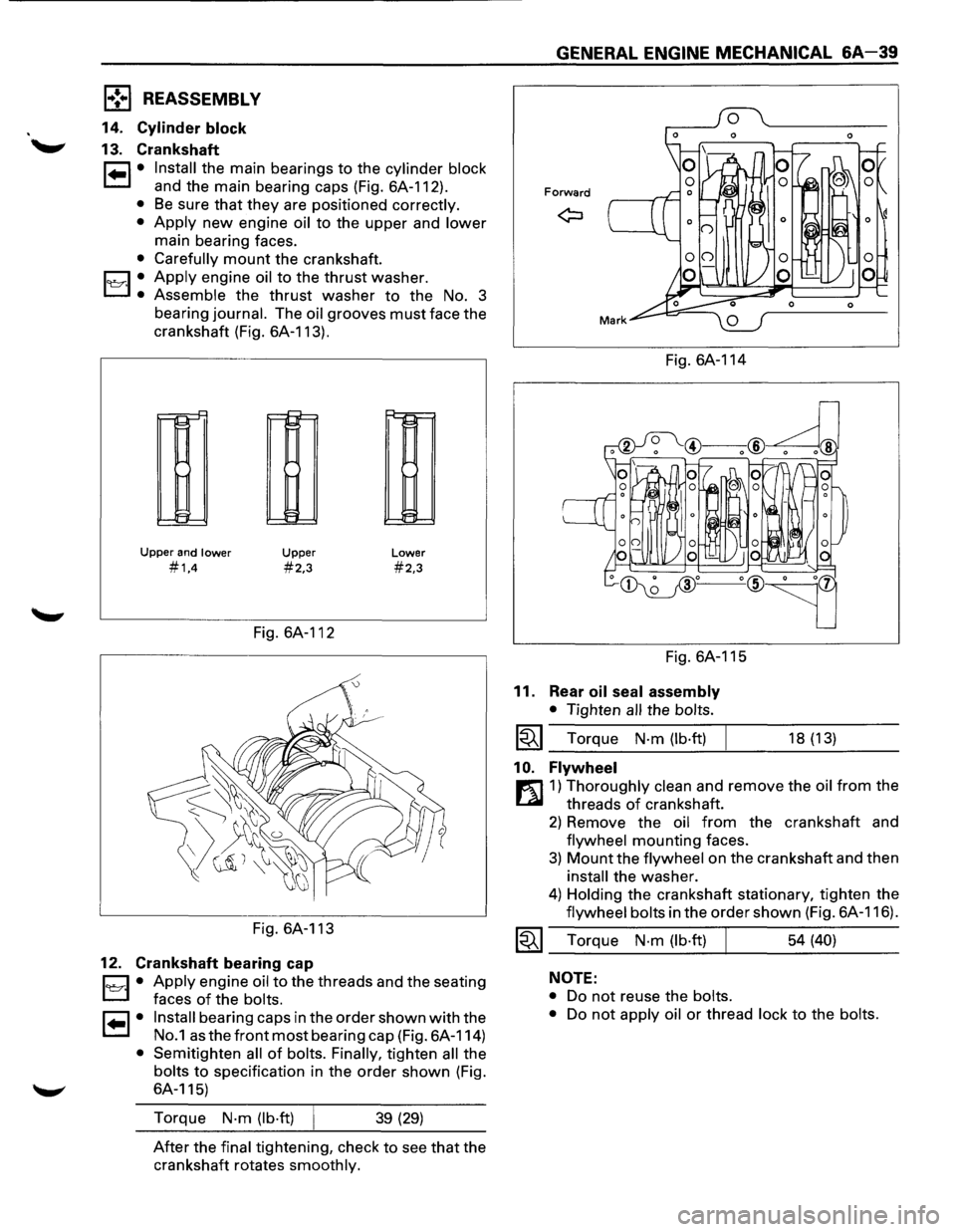
1,.!.,1 REASSEMBLY
14. Cylinder block
13. Crankshaft
1•1• Install the main bearings to the cylinder block
and the main bearing caps (Fig. 6A-112).
• Be sure that they are positioned correctly.
•
Apply new engine oil to the upper and lower
main bearing faces.
• Carefully mount the crankshaft.
1~·1 .• Apply engine oil to the thrust washer.
Assemble the thrust washer to the No. 3
bearing
journal. The oil grooves must face the
crankshaft (Fig. 6A-113).
r--!::"
11-1
~
Upper and lower
#1,4
Upper
#2,3
Fig. 6A-112
Fig. 6A-113
12. Crankshaft bearing cap
Lower
#2,3
D • Apply engine oil to the threads and the seating
L:J faces of the bolts.
I• I• Install bearing caps in the order shown with the
No.1 as the front most bearing cap (Fig. 6A-114)
• Semitighten all of bolts. Finally, tighten all the
bolts to specification in the order shown (Fig.
6A-115)
Torque
N·m (lb·ft) 39 (29)
After the final tightening, check to see that the
crankshaft rotates
smoothly.
GENERAL ENGINE MECHANICAL &A-39
Forward
Fig. 6A-114
Fig. 6A-115
11. Rear oil seal assembly
• Tighten all the bolts.
~~~ Torque N·m (lb·ft)
1 0. Flywheel
18 (13)
r:l]1) Thoroughly clean and remove the oil from the
threads
of crankshaft.
2) Remove the oil from the crankshaft and
flywheel mounting faces.
3) Mount the flywheel on the crankshaft and then
install the washer.
4) Holding the crankshaft stationary, tighten the
flywheel bolts in the order shown (Fig. 6A-116).
~~~ Torque N·m (lb·ft) 54 (40)
NOTE:
•
Do not reuse the bolts.
•
Do not apply oil or thread lock to the bolts.
Page 556 of 1928
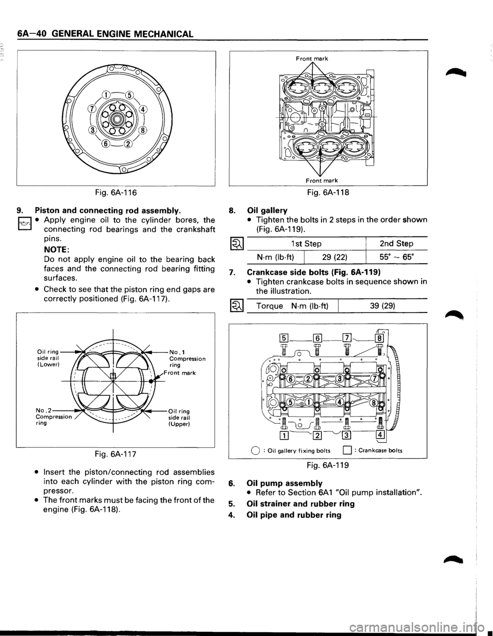
6A-40 GENERAL ENGINE MECHANICAL
Fig. 6A-116
9. Piston and connecting rod assembly.
Cl • Apply engine oil to the cylinder bores, the
L:J connecting rod bearings and the crankshaft
pins.
NOTE:
Do not apply engine oil to the bearing back
faces and the connecting rod bearing fitting
surfaces.
• Check to see that the piston ring end gaps are
correctly positioned (Fig. 6A-117).
Oil ring--~~~=!==:::;:,.::~~--No.1 side rail Compression (Lower) ring
Front mark
No. 2--~~~~i::::::=~~;(.,.--Oil ring Compression side rail ring (Upper)
Fig. 6A-117
• Insert the piston/connecting rod assemblies
into each cylinder with the piston ring com
pressor.
• The front marks must be facing the front of the
engine (Fig. 6A-118).
8.
Front mark
Front mark
Fig. 6A-118
Oil gallery
• Tighten the bolts in 2 steps in the order shown
(Fig. 6A-119).
1~1 _________ 1s_t,s_te~p ________ +-_2_n_d_S_t_e_p ___
7.
N·m (lb·ftl 29 (22) ss· -ss·
Crankcase side bolts (Fig. &A-119)
• Tighten crankcase bolts in sequence shown in
the
illustration.
I~I __ T_o_r~qu_e __ N_·_m __ (lb_·ft_)~ ______ 3_9_(2_9_l ____ _
Q : Oil gallery fixing bolts 0 : Crankcase bolts
Fig. 6A-119
6. Oil pump assembly
• Refer to Section 6A 1 "Oil pump installation".
5. Oil strainer and rubber ring
4.
Oil pipe and rubber ring
•
Page 612 of 1928
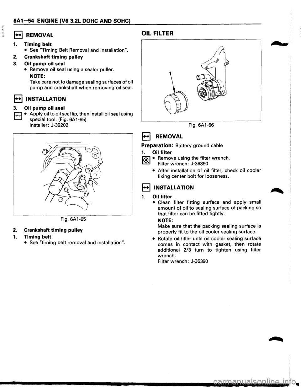
6A1-54 ENGINE (V6 3.2L DOHC AND SOHC)
1••1 REMOVAL
1. Timing belt
• See "Timing Belt Removal and Installation".
2. Crankshaft timing pulley
3. Oil pump oil seal
• Remove oil seal using a sealer puller.
NOTE:
Take care not to damage sealing surfaces of oil
pump and crankshaft when removing oil seal.
1••1 INSTALLATION
3. Oil pump oil seal
Cl • Apply oil to oil seal lip, then install oil seal using
L..:::::.l special tool. (Fig. 6A1-65)
Installer: J-39202
Fig. 6A1-65
2. Crankshaft timing pulley
1. Timing belt
• See "timing belt removal and installation".
OIL FILTER
1
Fig. 6A1-66
E) REMOVAL
Preparation: Battery ground cable
1. Oil filter
lia\l • Remove using the filter wrench.
~ Filter wrench: J-36390
• After installation of oil filter, check oil cooler
fixing center bolt for looseness.
1••1 INSTALLATION
1. Oil filter
• Clean filter fitting surface and apply small
amount of oil to sealing surface of packing so
that filter can be fitted tightly.
NOTE:
Make sure that the packing sealing surface is
properly fit to the oil cooler sealing surface.
• Rotate oil filter until oil cooler sealing surface
comes in contact
with gasket, then rotate
additional 2/3 turn to tighten using filter
wrench.
Filter wrench: J-36390
, ...
Page 613 of 1928
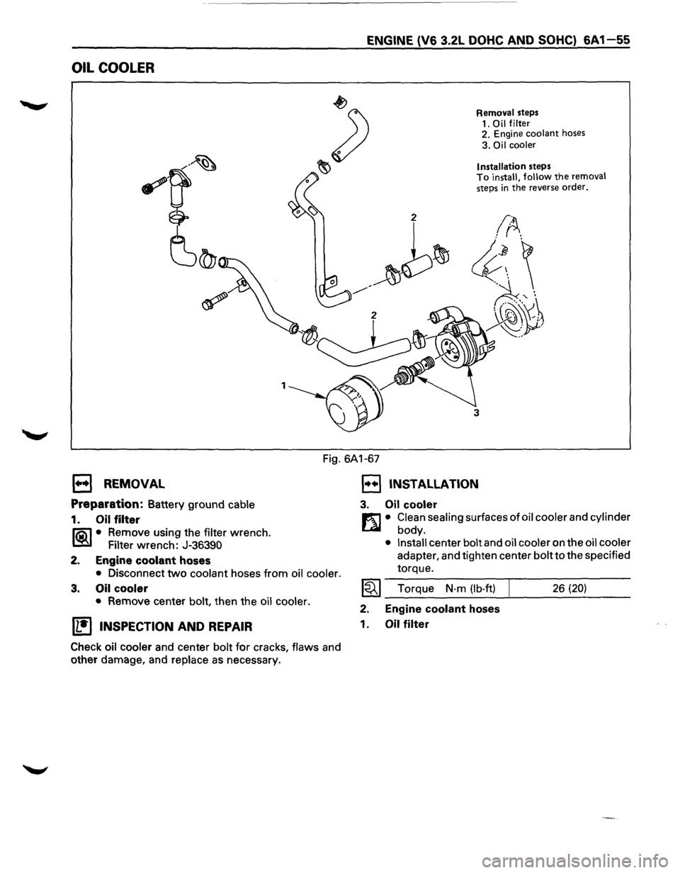
OIL COOLER
1
ENGINE (V6 3.2L DOHC AND SOHC) 6A 1-55
Removal steps
1.
Oil filter 2. Engine coolant hoses
3. Oil cooler
Installation
steps To install, follow the removal steps in the reverse order.
3
Fig. 6A1-67
1••1 REMOVAL
Preparation: Battery ground cable
1. Oil filter
li5\1 • Remove using the filter wrench.
~ Filter wrench: J-36390
2. Engine
coolant hoses
• Disconnect two coolant hoses from oil cooler.
3. Oil cooler
• Remove center bolt, then the oil cooler.
U!)INSPECTION AND REPAIR
Check oil cooler and center bolt for cracks, flaws and
other damage, and
replace as necessary.
1••1 INSTALLATION
3. Oil cooler
m • Clean sealing surfaces of oil cooler and cylinder
L41 body.
• Install center bolt and oil cooler on the oil cooler
adapter, and tighten center bolt to the specified
torque.
~~~ Torque N·m (lb·ft) 26 (20)
2. Engine coolant hoses
1.
Oil filter
Page 631 of 1928
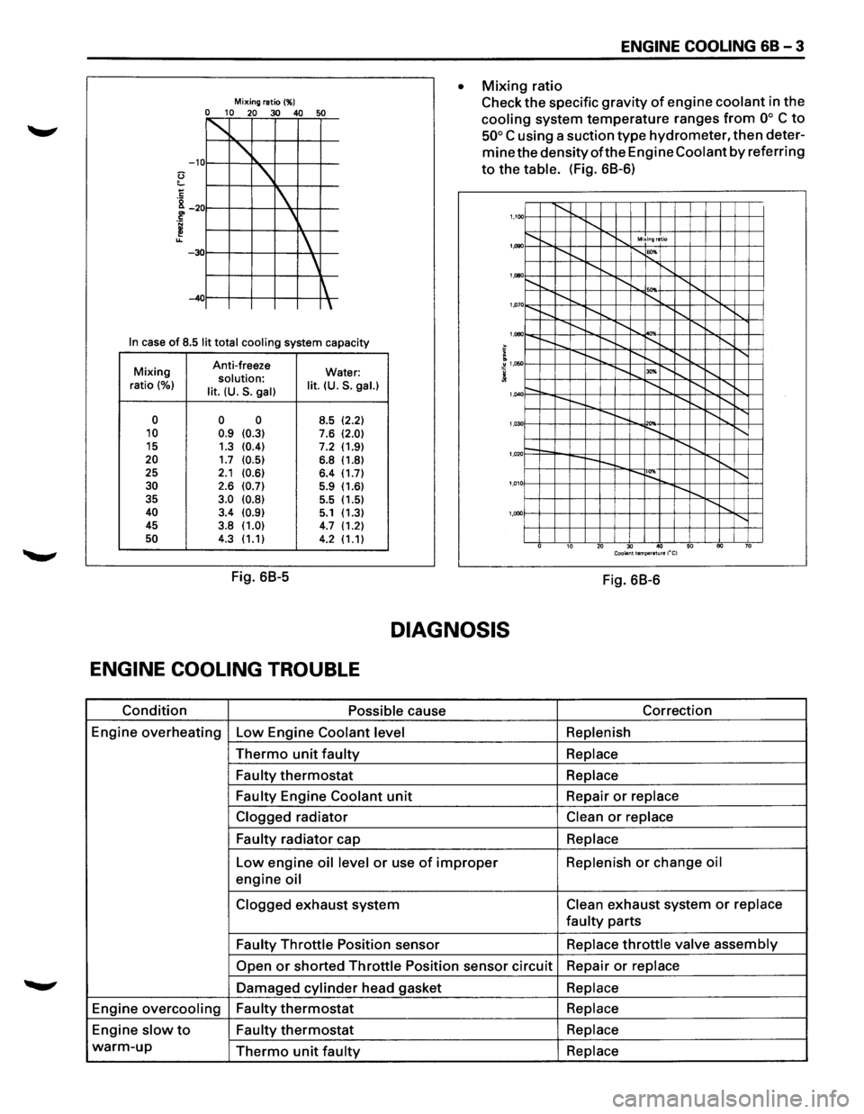
Mixing ratio(%) 0 10 20 30 40 50
~
' -10
'
1
' -30
~ -40
In case of 8.5 lit total cooling system capacity
Mixing Anti-freeze
Water: solution: ratio (%) lit. (U.S. gal) lit. (U.S. gal.)
0 0 0
8.5 (2.2) 10 0.9 (0.3) 7.6 (2.0) 15
1.3 (0.4) 7.2 (1.9) 20 1.7 (0.5) 6.8 (1.8)
25 2.1 (0.6) 6.4 (1.7) 30 2.6 (0.7) 5.9 (1.6)
35 3.0 (0.8) 5.5
(1.5) 40 3.4 (0.9) 5.1 (1.3)
45 3.8 (1.0) 4.7 (1.2) 50 4.3 (1.1)
4.2 (1.1)
Fig. 68-5
ENGINE COOLING 68-3
• Mixing ratio
Check
the specific gravity of engine coolant in the
cooling system temperature ranges from oo C to
50° C using a suction type hydrometer, then deter
mine the densityofthe Engine Coolant by referring
to the table. (Fig. 68-6)
1,100 1'-........ ........ ...... .............. Mixing ratio
~"""--r-... 1'-""' 1,1)90
........ ...... ........ ........ .......... '
1,000
'"" 1,07 o......_ 1'-........ I'-.......... I"-........ .......
I"-........ ..........
................. I"-........
'
1,080
....... I"-........ ~ ........ ......
........ "'" ~"""--r--..... 1,050
r-. ........ ~ .......... ......
---
........ ........ 1,040
r-.... !'--.. 1'-0 '"" ~"""--1'-.... ........ 1,03
1--....... ........ r--~ ........
'
1,020
....... ~ 1'-0 ~"""---.... 1,01
...... ,
'
1,000
10 20 30 40 50 60 70 Coolant temperature ("C)
Fig. 68-6
DIAGNOSIS
ENGINE COOLING TROUBLE
Condition Possible cause Correction
Engine
overheating Low Engine Coolant level Replenish
Thermo unit faulty Replace
Faulty
thermostat Replace
Faulty
Engine Coolant unit Repair or replace
Clogged
radiator Clean or replace
Faulty
radiator cap Replace
Low engine oil level or use of improper Replenish or change oil
engine oil
Clogged exhaust system Clean exhaust system or replace
faulty parts
Faulty Throttle Position sensor Replace throttle valve assembly
Open or shorted Throttle Position sensor circuit Repair or replace
Damaged cylinder head gasket Replace
Engine overcooling Faulty thermostat Replace
Engine slow to Faulty thermostat Replace
warm-up Thermo unit faulty Replace
Page 632 of 1928
68 - 4 ENGINE COOLING
ON-VEHICLE SERVICE
DRAINING AND REFILLING COOLING
SYSTEM
Before draining the cooling system, inspect the sys
tem and perform any necessary service to ensure that
it is clean, does not leak and is in proper working
order. The Engine Coolant (EC) level should be be
tween the "MIN" and "MAX" lines of reserve tank
when the engine is cold. If low, check for leakage and
add
EC up to the "MAX" line. There should not be any
excessive deposit of rust or scales around the radiator
cap
or radiator filler hole, and the EC should also be
free
from oil. Replace the EC if excessively dirty.
1. Completely drain the cooling system by opening
the drain petcock at the bottom of the radiator.
2. Remove the radiator cap.
W WARNING
To avoid the danger of being burned, do not
remove the cap while the engine and radiator
are still hot. Scalding fluid and steam can be
blown out under pressure.
3. Disconnect all hoses from the EC reserve tank.
Scrub and clean the inside of the reserve tank with
soap and water. Flush it well with clean water,
then drain it. Install the reserve tank and hoses.
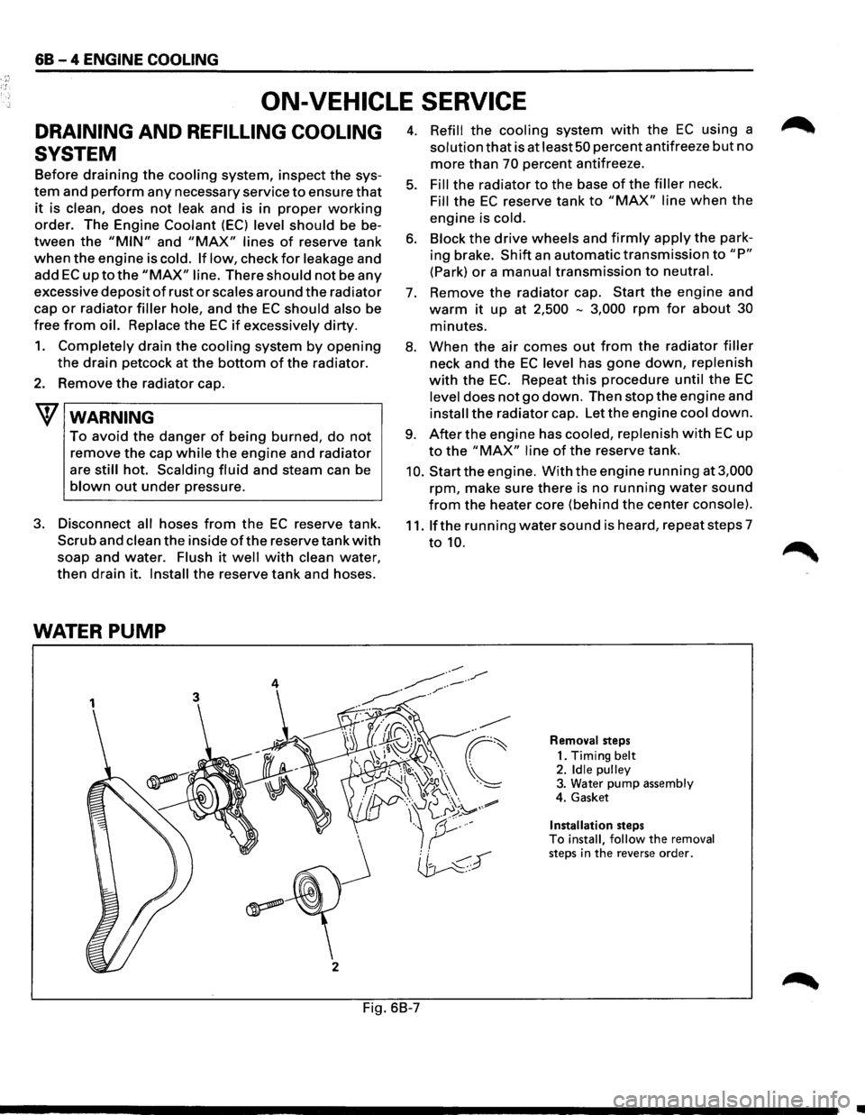
WATER PUMP
3
j
2
4. Refill the cooling system with the EC using a
solution that is at least 50 percent antifreeze but no
more than 70 percent antifreeze.
5. Fill the radiator to the base of the filler neck.
Fill the EC reserve tank to "MAX" line when the
engine is cold.
6. Block the drive wheels and firmly apply the park
ing brake.
Shift an automatic transmission to "P"
(Park) or a manual transmission to neutral.
7. Remove the radiator cap. Start the engine and
warm it up at 2,500 -3,000 rpm for about 30
minutes.
8. When the air comes out from the radiator filler
neck and the EC level has gone down, replenish
with the EC. Repeat this procedure until the EC
level does not go down. Then stop the engine and
install the radiator cap. Let the engine cool down.
9. After the engine has cooled, replenish with EC up
to the "MAX" line of the reserve tank.
10. Start the engine. With the engine running at 3,000
rpm, make sure there is no running water sound
from the heater core (behind the center console).
11. If the running water sound is heard, repeat steps 7
to 10.
Removal steps
1. Timing
belt 2. Idle pulley 3. Water pump assembly
4. Gasket
Installation steps To install, follow the removal steps in the reverse order.
Fig. 6B-7
•