check oil ISUZU TROOPER 1995 User Guide
[x] Cancel search | Manufacturer: ISUZU, Model Year: 1995, Model line: TROOPER, Model: ISUZU TROOPER 1995Pages: 1928
Page 92 of 1928
1 D-4 COMPRESSOR OVERHAUL
6. Perform oil return operation.
7. Remove the compressor and recheck the
amount of oil.
8. Adjust the compressor oil, if necessary.
Collected Amount
more than 90cc
(3.0
fl.oz.)
Charging Amount
same as collected amount
less than 90cc (3.0 fl.oz.) 90cc (3.0 fl.oz.)
Checking and Adjusting for Compressor
Replacement
150cc (5.0 fl.oz.) of oil is charged in compressor
(service parts).
So it is necessary to drain the
proper
amount of oil from the new compressor.
1. Perform oil return operation.
2. Discharge and recover refrigerant and remove
the compressor.
3. Drain the compressor oil and measure the
extracted
oil.
4. Check the compressor oil for contamination.
5. Adjust oil level as required.
Amount of oil drained
from used compressor
less than 90cc
(3.0
fl.oz.)
Draining amount of oil
from new compressor
Same as drained
amount
more than 90cc (3.0 fl.oz.) 90cc (3.0 fl.oz.)
6. Evacuate, charge and perform oil return oper
ation.
7. Check system operation.
CONTAMINATION OF COMPRESSOR OIL
Unlike engine oil, no cleaning agent is added to the
compressor
oil. Even if the compressor runs for a
long period
of time (approximately 1 season), the
oil never becomes contaminated as long
as there is
nothing
wrong with the compressor or its method
of use.
Inspect the extracted oil for any of the following
conditions:
• The capacity of the oil has increased.
• The oil has changed color to red.
• Foreign substances, metal powder, etc., are
present in the oil.
If any of these conditions exists, compressor oil
is contaminated. Whenever contaminated com
pressor
oil is discovered, the receiver/dryer must
be
replaced.
OIL RETURN OPERATION
There is close affinity between the oil and the
refrigerant. During normal operation, part
of the oil
recirculates
with the refrigerant in the system.
When checking the
amount of oil in the system, or
replacing any component of the system, the com
pressor
must be run in advance for oil return oper
ation. The procedure is as
follows:
1. Open the all doors and engine hood.
2. Start the engine and air conditioning switch is
"ON" and Set the fan control knob at its hig
hest position.
3. Run the compressor for more than 20 minutes
between
800 and 1,000 rpm in order to operate
the system.
4. Stop the engine.
REPLACEMENT OF COMPONENT PARTS
When replacing system component parts, supply
the following
amount of oil to the component parts
to be installed.
Component parts to be installed Amount of oil
Evaporator 50cc
(1.7
fl.oz.)
Condenser 30cc
(1.0 fl.oz.)
Receiver/dryer 30cc
(1.0 fl.oz.)
Refrigerant line (one piece) 1 Occ (0.3 fl. oz.)
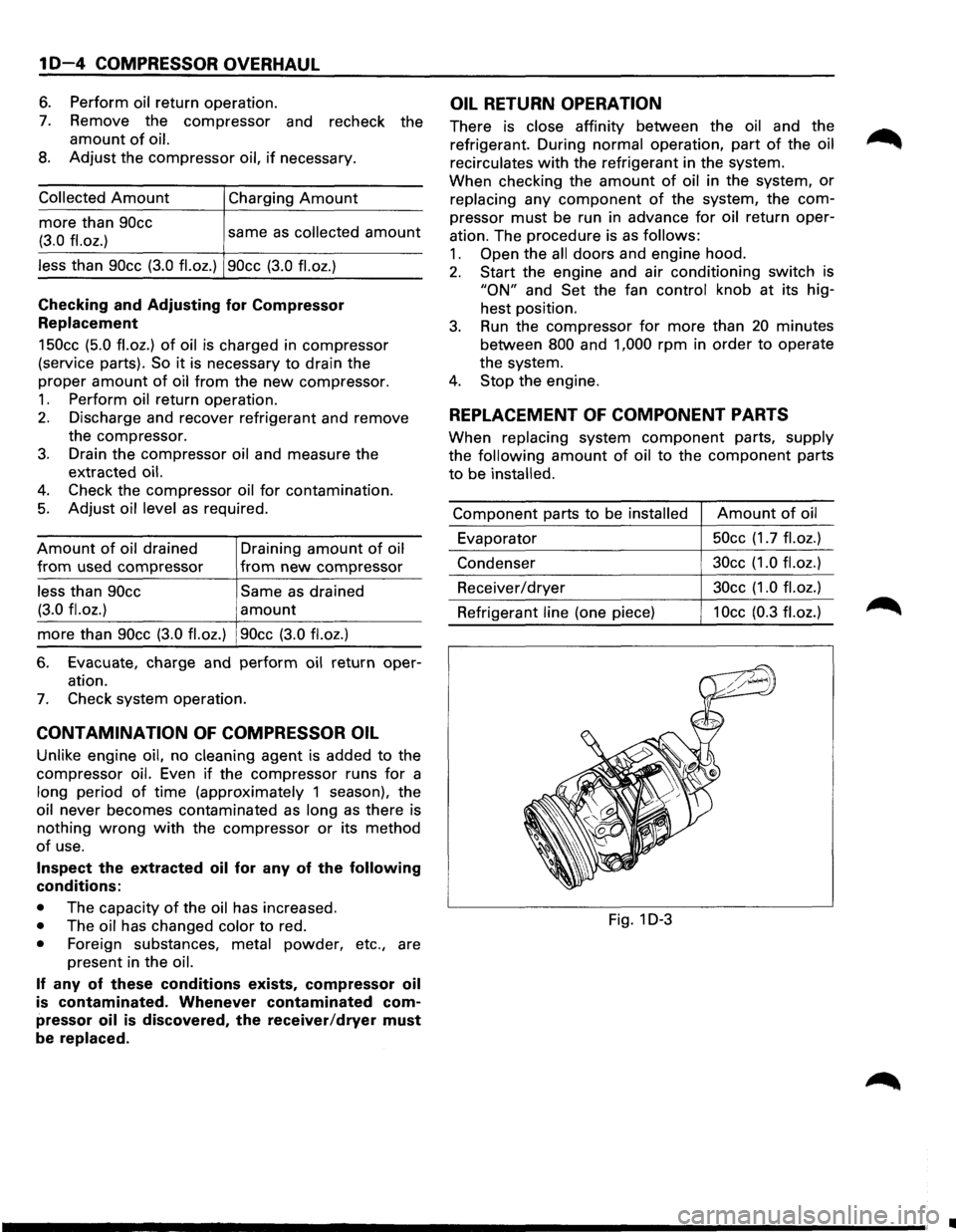
Fig. 1 D-3
•
Page 94 of 1928
![ISUZU TROOPER 1995 User Guide 1 D-6 COMPRESSOR OVERHAUL
Fig. 1 D-7
Fig. 1D-8
Fig. 1
D-9
Fig. 1D-10
(L!] INSPECTION AND REPAIR
Drive Plate
If the frictional surface shows signs of damage due
to excessive heat, the driv](/img/61/57183/w960_57183-93.png "ISUZU TROOPER 1995 User Guide 1 D-6 COMPRESSOR OVERHAUL
Fig. 1 D-7
Fig. 1D-8
Fig. 1
D-9
Fig. 1D-10
(L!] INSPECTION AND REPAIR
Drive Plate
If the frictional surface shows signs of damage due
to excessive heat, the driv")
1 D-6 COMPRESSOR OVERHAUL
Fig. 1 D-7
Fig. 1D-8
Fig. 1
D-9
Fig. 1D-10
(L!] INSPECTION AND REPAIR
Drive Plate
If the frictional surface shows signs of damage due
to excessive heat, the drive plate and pulley should
be replaced.
Pulley Assembly
Check the appearance of the pulley assembly. If the
frictional surface
of the pulley shows signs of
excessive grooving due to slippage, both the pulley
and drive plate should be replaced. The frictional
surfaces
of the pulley assembly should be cleaned
with a suitable solvent before reinstallation.
Coil
Check coil for loose connector or cracked insul
ation.
I••! INSTALLATION
7. Field coil
Align the located portion of the field coil and
compressor (Fig. 1
D-11 ).
Tighten the mounting screw to the specified
torque.
Torque
N·m (lb·in) 5 (44)
Fig. 1D-11
•
Page 141 of 1928
POWER STEERING SYSTEM TEST
TEST PROCEDURE
Test of fluid pressure in the power steering system is
performed to determine whether
or not the oil pump
and
power steering unit are functioning normally.
The power steering system test is method used to
identify and
isolate hydraulic circuit difficulties. Prior
to performing this test, the following inspections and
corrections,
if necessary, must be made.
[!) INSPECT
• Pump reservoir for proper fluid level.
•
Pump belt for proper tension.
• Pump driver pulley condition.
1. Place a container under the pump to catch the
fluid when disconnecting or connecting the
hoses.
2. With the engine NOT running, disconnect the
pressure hose
at the power steering pump and
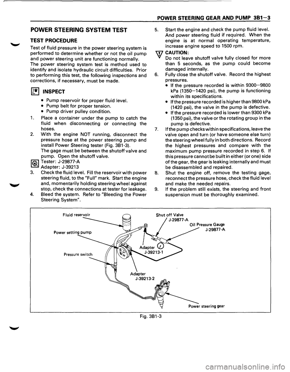
install Power Steering tester (Fig. 3B1-3).
The gage
must be between the shutoff valve and
pump.
Open the shutoff valve.
li5\l Tester: J-29877-A
~ Adapter: J-39213
3. Check the fluid level. Fill the reservoir with power
steering fluid, to the "Full" mark. Start the engine
and,
momentarily holding steering wheel against
stop, check the connections at tester
for leakage.
4. Bleed the system. Refer to "Bleeding the Power
Steering
System".
POWER STEERING GEAR AND PUMP 381-3
5. Start the engine and check the pump fluid level.
And power steering fluid if required. When the
engine is at
normal operating temperature,
increase engine speed to 1500 rpm.
U7 CAUTION:
VI Do not leave shutoff valve fully closed for more
than 5 seconds,
as the pump could become
damaged
internally.
6. Fully close the shutoff valve. Record the highest
pressures.
• If the pressure recorded is within 9300-9800
kPa (1350-1420 psi), the pump is functioning
within its specifications.
• If the pressure recorded is higher than 9800 kPa
(1420 psi), the valve in the pump is defective.
• If the pressure recorded is lower than 9300 kPa
(1350 psi), the valve or the rotating group in the
pump is defective.
7. If the pump checks within specifications, leave the
valve open and turn (or have someone else turn)
the steering
wheel fully in both directions. Record
the highest pressures and compare
with the
maximum pump pressure recorded in step
6. If
this pressure cannot be built in either (or one) side
ofthe gear, the gear is leaking internally and must
be disassembled and repaired.
8. Shut the engine off, remove the testing gage,
reconnect the pressure hose, check the
fluid level
and make the needed repairs.
9. If the problem still exists, the steering and front
suspension must be thoroughly examined.
Shut off Valve
J-29877-A
Oil Pressure Gauge
J-29877-A
Fig. 3B1-3
Page 142 of 1928
381 - 4 POWER STEERING GEAR AND PUMP
ON-VEHICLE SERVICE
MAINTENANCE
The hydraulic system should be kept clean and fluid
level in the reservoir should be checked at regular
intervals
and fluid added when required. Refer to
"MAINTENANCE AND LUBRICATION" in section OB
ofthe manual for type offluid to be used and intervals
for filling.
If the system contains some dirt, flush it as detailed
later
in this section. If it is exceptionally dirty, both the
pump and the gear must be completely disassembled
before further usage.
All tubes, hoses, and fittings should be inspected for
leakage at regular intervals. Fittings must be tight.
Make sure the clips, clamps and supporting tubes and
hoses are in
place and properly secured.
Power steering hoses and lines must not be twisted,
kinked or tightly bent. Air in the system will cause
spongy action and noisy operation. When a hose is
disconnected
or when fluid is lost, for any reason, the
system must be bled after refilling. Refer to "Bleeding
the Power Steering System" in this section.
FLUID LEVEL
1. Run the engine until the power steering fluid
reaches normal operating temperature, about
55°C (130°F), then shut the engine off.
2. Check the level of fluid in the reservoir.
3. If the fluid level is low, add power steering fluid
as specified in "MAINTENANCE AND LUBRI
CATION" in Section OB to the proper level and
install the receiver cap.
4. When checking the fluid level after the steering
system has been serviced,
air must be bled from
the system. Refer to "Bleeding the Power
Steering
System" in this section.
BLEEDING THE POWER STEERING
SYSTEM
When a power steering pump or gear has been
installed, or an oil line has been disconnected, the air
that has entered the system must be bled out before
the vehicle is operated. If air is allowed to remain in
the power steering fluid system, noisy and
unsatisfactory operation of the system may result.
BLEEDING PROCEDURE
When bleeding the system, and any time fluid is
added
to the power steering system, be sure to use
only power steering fluid as specified in
"MAINTENANCE AND LUBRICATION" in section OB.
1. Fill the pump fluid reservoir to the proper level
and let the fluid settle for at least two minutes.
2. Start the engine and let it run for a few seconds.
Do
not turn the steering wheel. Then turn the
engine off.
3. Add fluid if necessary.
4. Repeat the above procedure until the fluid level
remains constant after running the engine.
5. Raise the front end of the vehicle so that the
wheels are off the ground.
6. Start the engine. Slowly turn the steering wheel
right and left, lightly contacting the wheel stops.
7. Add power steering fluid if necessary.
8. Lower the vehicle and turn the steering wheel
slowly from lock to lock.
9. Stop the engine. Check the fluid level and refill
as required.
10.
If the fluid is extremely foamy, allow the vehicle
to stand a few minutes and repeat the above
procedure.
~ INSPECT
• Belt for tightness.
• Pulley for looseness or damage. The pulley
should not wobble with the engine running.
• Hoses so they are not touching any other parts
of the vehicle.
• Fluid level
and fill to the proper level.
FLUSHING THE POWER STEERING
SYSTEM
1. Raise the front end of the vehicle off the ground
until the wheels are free to turn.
2. Remove the fluid return line at the pump inlet
connector and plug the connector port on the
pump.
Position the line toward a large container to
catch the draining fluid.
3. While running the engine at idle, fill the reservoir
with new power steering fluid. Turn the steering
wheel in both directions. DO NOT contact wheel
stops or hold the wheel in a corner, or fluid will
stop and the pump will be in pressure relief mode.
A sudden
overflow from the reservoir may
develop if the wheel is held at a stop.
4. Install all the lines and hoses. Fill the system with
new power steering fluid and bleed the system
as described in "Bleeding The Power Steering
System". Operate the engine for about 15
minutes.
Remove the
pump return line at the pump inlet
and plug the connection on the pump. While
refilling the reservoir, check the draining fluid for
contamination. If foreign material is still evident,
replace all lines, disassemble and clean or replace
the power steering system components. Do not
re-use any drained power steering fluid.
~
~
Page 153 of 1928
[1!) INSPECTION AND REPAIR
Make all necessary adjustments, repairs, and part
replacements
if wear, damage, or other problems are
discovered during inspection.
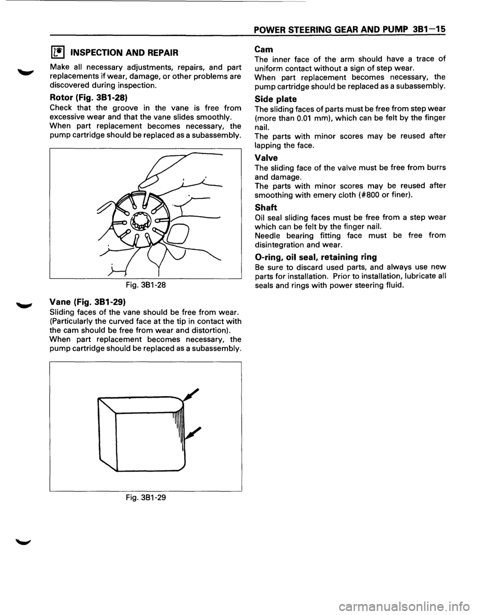
Rotor (Fig. 381-28)
Check that the groove in the vane is free from
excessive wear and that the vane slides smoothly.
When part replacement becomes necessary, the
pump cartridge
should be replaced as a subassembly.
Fig. 381-28
Vane (Fig. 381-29)
Sliding faces of the vane should be free from wear.
(Particularly the curved face at the tip in contact with
the cam should be free from wear and distortion).
When part
replacement becomes necessary, the
pump cartridge should be replaced as a subassembly.
Fig. 381-29
POWER STEERING GEAR AND PUMP 381-15
Cam
The inner face of the arm should have a trace of
uniform contact without a sign of step wear.
When part
replacement becomes necessary, the
pump cartridge should be replaced as a subassembly.
Side plate
The sliding faces of parts must be free from step wear
(more than 0.01 mm), which can be felt by the finger
nail.
The parts with minor scores may be reused after
lapping the face.
Valve
The sliding face of the valve must be free from burrs
and damage.
The parts
with minor scores may be reused after
smoothing
with emery cloth (#800 or finer).
Shaft
Oil seal sliding faces must be free from a step wear
which can be felt by the finger nail.
Needle
bearing fitting face must be free from
disintegration and wear.
0-ring, oil seal, retaining ring
Be sure to discard used parts, and always use new
parts for installation. Prior to installation, lubricate all
seals
and rings with power steering fluid.
Page 172 of 1928
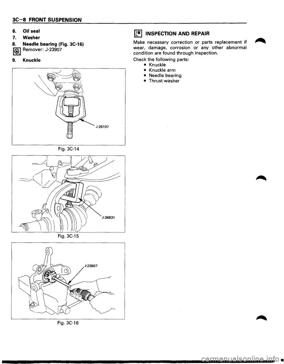
3C-8 FRONT SUSPENSION
6. Oil seal
7. Washer
8. Needle bearing (Fig. 3C-16)
1®.1 Remover: J-23907
9. Knuckle
Fig. 3C-14
Fig. 3C-15
Fig. 3C-16
J-29107
11!) INSPECTION AND REPAIR
Make necessary correction or parts replacement if ~
wear, damage, corrosion or any other abnormal
condition are found through inspection.
Check the
following parts:
• Knuckle
• Knuckle arm
• Needle bearing
• Thrust washer
•
Page 250 of 1928
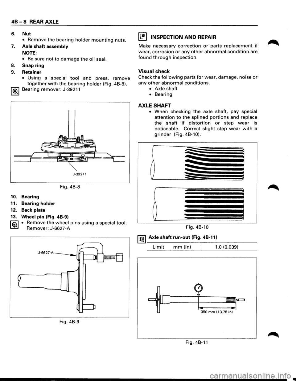
48 - 8 REAR AXLE
6. Nut
• Remove the bearing holder mounting nuts.
7. Axle shaft assembly
NOTE:
• Be sure not to damage the oil seal.
8. Snap ring
9. Retainer
• Using a special tool and press, remove
together with the bearing holder (Fig. 4B-8).
1 ®I Bearing remover: J-39211
J-39211
Fig. 4B-8
10. Bearing
11. Bearing
holder
12. Back plate
13. Wheel pin (Fig. 4B-9)
1®.1 • Remove the wheel pins using a special tool.
Remover: J-6627-A
J-6627-A
Fig. 4B-9
I L•l INSPECTION AND REPAIR
Make necessary correction or parts replacement if
wear, corrosion or any other abnormal condition are
found through inspection.
Visual check
Check the following parts for wear, damage, noise or
any other abnormal conditions.
• Axle shaft
• Bearing
AXLE SHAFT
• When checking the axle shaft, pay special
attention to the splined portions and replace
the shaft if distortion or step wear is
noticeable. Correct slight step wear with a
grinder (Fig. 4B-10).
Fig. 4B-10
~~~ Axle shaft run-out (Fig. 4B-11)
Limit mm(in) 1.0 (0.039)
350 mm (13.78 in)
Fig. 4B-11
•
Page 252 of 1928
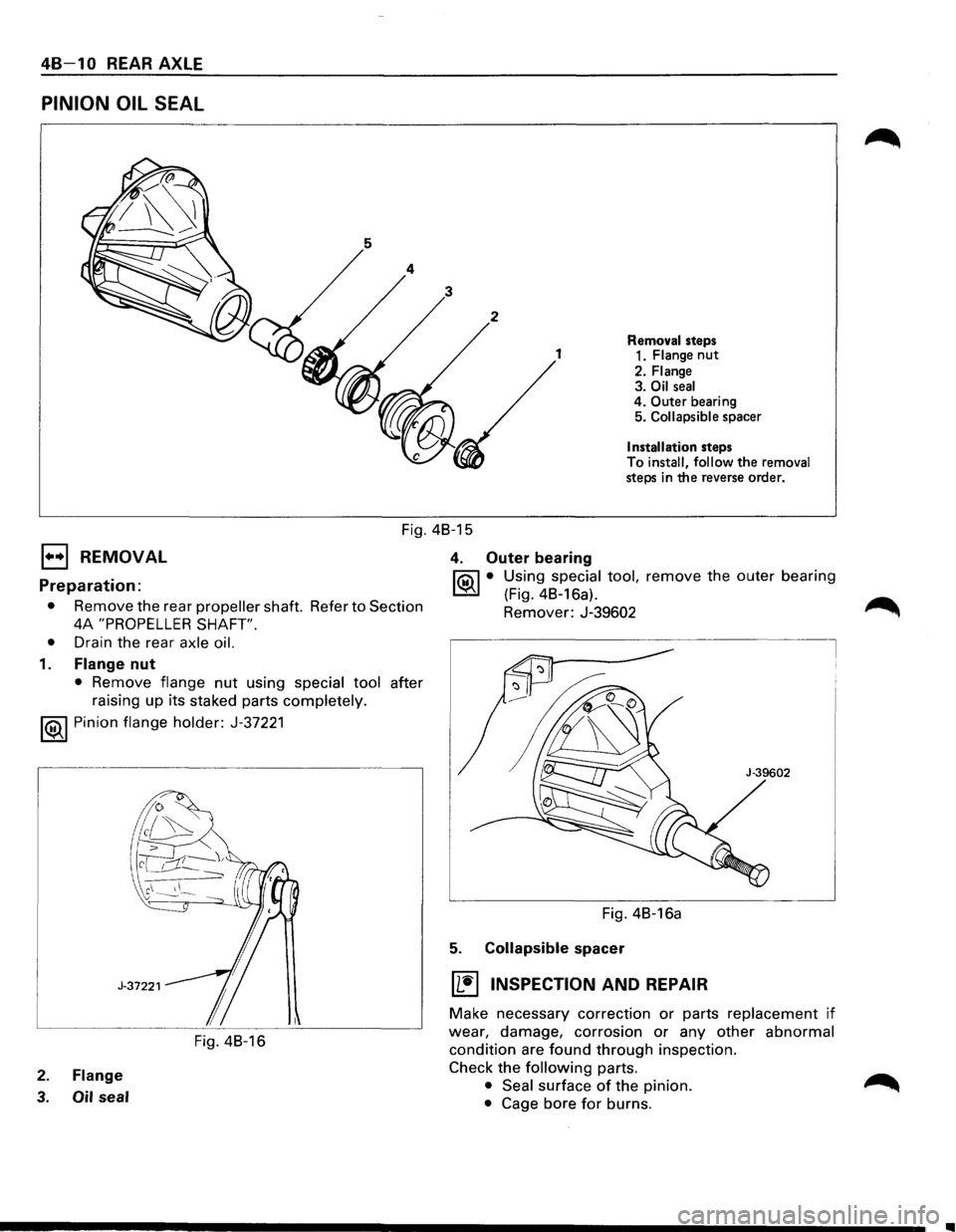
48-1 0 REAR AXLE
PINION OIL SEAL
Removal steps
1 1. Flange nut
2. Flange 3. Oil seal 4. Outer bearing
5. Collapsible spacer
Installation steps
To
install, follow the removal steps in the reverse order.
Fig. 48-15
1••1 REMOVAL 4. Outer bearing
~ • Using special tool, remove the outer bearing Preparation: ~ (Fig. 48-16a).
• Remove the rear propeller shaft. Refer to Section Remover: J-39602 ~
4A "PROPELLER SHAFT".
•
Drain the rear axle oil.
1. Flange nut
• Remove flange nut using special tool after
raising up its staked parts
completely.
1®..1 Pinion flange holder: J-37221
Fig. 48-16
2. Flange
3. Oil seal
Fig. 4B-16a
5. Collapsible spacer
IL~I INSPECTION AND REPAIR
Make necessary correction or parts replacement if
wear, damage, corrosion or any other abnormal
condition are found through inspection.
Check
the following parts.
• Seal surface of the pinion.
• Cage bore for burns.
..
Page 266 of 1928
48-24 REAR AXLE
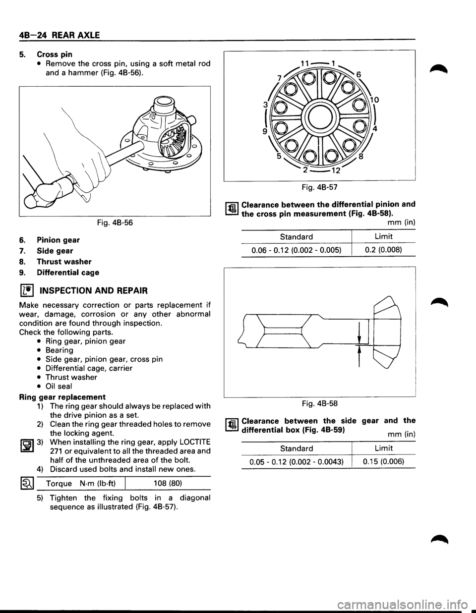
5. Cross pin
• Remove the cross pin, using a soft metal rod
and a hammer (Fig. 48-56).
Fig. 48-56
6. Pinion gear
7. Side gear
8. Thrust washer
9. Differential cage
(1!] INSPECTION AND REPAIR
Make necessary correction or parts replacement if
wear, damage, corrosion or any other abnormal
condition are found through inspection.
Check the following parts.
• Ring gear, pinion gear
• Bearing
• Side gear, pinion gear, cross pin
• Differential cage, carrier
• Thrust washer
• Oil seal
Ring gear replacement
1) The ring gear should always be replaced with
the drive pinion as a set.
2) Clean the ring gear threaded holes to remove
the
locking agent.
~~~3) When installing the ring gear, apply LOCTITE
271 or equivalent to all the threaded area and
half of the unthreaded area of the bolt.
4) Discard used bolts and install new ones.
1~1 Torque N·m (lb·ft) 108 (80)
5) Tighten the fixing bolts in a diagonal
sequence as illustrated (Fig. 48-57). Fig.
48-57
l'fil Clearance between the differential pinion and
1..!:.1 the cross pin measurement (Fig. 48-58).
mm (in)
Standard Limit
0.06 -0.12
(0.002 -0.005) 0.2
(0.008)
Fig. 48-58
l'fil Clearance between the side gear and the
1..!:.1 differential box (Fig. 48-59) mm (in)
Standard
Limit
0.05 -0.12 (0.002 -0.0043) 0.1 5 (0.006)
Page 270 of 1928
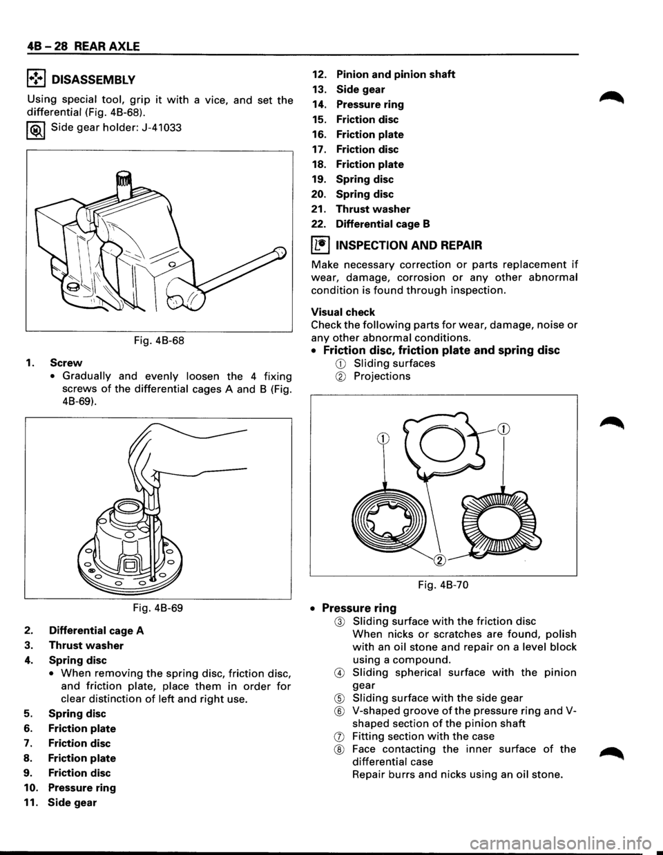
48 -28 REAR AXLE
l•!-.1 DISASSEMBLY
Using special tool, grip it with a vice, and set the
differential (Fig. 48-68).
I ®.1 Side gear holder: J-41 033
Fig. 48-68
1.
Screw
• Gradually and evenly loosen the 4 fixing
screws of the differential cages A and 8 (Fig.
48-69).
Fig. 48-69
2. Differential cage A
3. Thrust washer
4. Spring disc
• When removing the spring disc, friction disc,
and
friction plate, place them in order for
clear distinction of left and right use.
5. Spring disc
6. Friction plate
7. Friction disc
8. Friction plate
9. Friction disc
10. Pressure ring
11. Side gear
12. Pinion and pinion shaft
13. Side gear
14. Pressure
ring
15. Friction disc
16. Friction plate
17. Friction disc
18.
Friction plate
19. Spring disc
20. Spring disc
21.
Thrust washer
22. Differential cage B
IL•IINSPECTION AND REPAIR
Make necessary correction or parts replacement if
wear, damage, corrosion or any other abnormal
condition is found through inspection.
Visual check
Check
the following parts for wear, damage, noise or
any other abnormal conditions.
• Friction disc, friction plate and spring disc
CD Sliding surfaces
® Projections
Fig. 48-70
• Pressure ring
@ Sliding surface with the friction disc
When nicks or scratches are found, polish
with an oil stone and repair on a level block
using a
compound.
@ Sliding spherical surface with the pinion
gear
® Sliding surface with the side gear
® V-shaped groove of the pressure ring and V
shaped section
of the pinion shaft
(j) Fitting section with the case
® Face contacting the inner surface of the
differential case
Repair
burrs and nicks using an oil stone.