check oil ISUZU TROOPER 1995 Repair Manual
[x] Cancel search | Manufacturer: ISUZU, Model Year: 1995, Model line: TROOPER, Model: ISUZU TROOPER 1995Pages: 1928
Page 635 of 1928
B INSTALLATION
3. Thermostat
• Install thermostat into the thermostat hous
ing, making sure
that the jiggle valve in up
position.
2. Packing
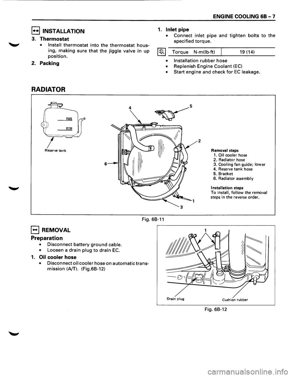
RADIATOR
Reserve tank
6
ENGINE COOLING 68-7
1. Inlet pipe
• Connect inlet pipe and tighten bolts to the
specified torque.
I~~ Torque N·mOb·ft) 19 (14)
• Installation rubber hose
• Replenish Engine Coolant (EC)
• Start engine and check for EC leakage.
2
Removal steps
1.
Oil cooler hose 2. Radiator hose
3. Cooling fan guide; lower
4. Reserve tank hose
5. Bracket
6. Radiator assembly
Installation steps
To install, follow the removal
steps in the reverse order.
Fig. 68-11
EJ REMOVAL
Preparation
• Disconnect battery ground cable.
•
Loosen a drain plug to drain EC.
1. Oil cooler hose
• Disconnect oil cooler hose on automatic trans
mission
(NT). (Fig.68-12)
Drain plug Cushion rubber
Fig. 68-12
Page 638 of 1928
68 -10 ENGINE COOLING
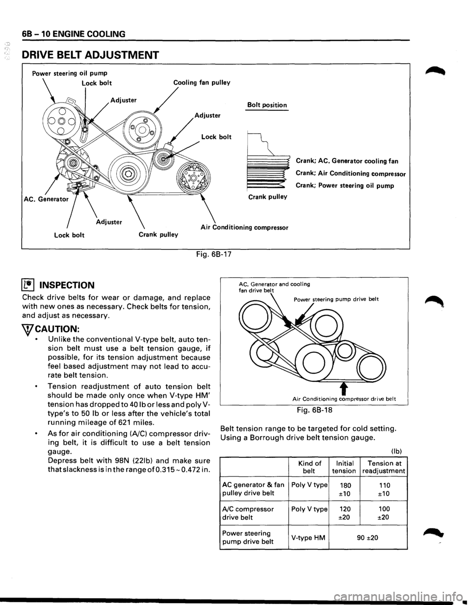
DRIVE BELT ADJUSTMENT
Power steering oil pump
Lock bolt
Bolt position
Adjuster
Crank
pulley
Crank; AC. Generator cooling fan
Crank;
Air Conditioning compressor
Crank; Power steering
oil pump
Air Conditioning compressor
Lock bolt Crank pulley
Fig. 68-17
(b!] INSPECTION
Check drive belts for wear or damage, and replace
with new ones as necessary. Check belts for tension,
and
adjust as necessary.
WCAUTION:
• Unlike the conventional V-type belt, auto ten
sion
belt must use a belt tension gauge, if
possible, for its tension adjustment because
feel based adjustment may not lead to accu
rate
belt tension.
Tension
readjustment of auto tension belt
should be made only once when V-type HM'
tension has dropped to 40 lb or less and polyV
type's to 50 lb or less after the vehicle's total
running mileage of 621 miles.
As for air conditioning (A/C) compressor driv
ing belt, it is difficult to use a belt tension
gauge.
Depress
belt with 98N (221b) and make sure
that slackness is in the range of0.315-0.472 in.
AC. Generator and cooling fan drive belt
Air Conditioning compressor drive belt
Fig. 68-18
Belt tension range to be targeted for cold setting.
Using a
Borrough drive belt tension gauge.
(I b)
Kind of Initial Tension at belt tension readjustment
AC generator & fan Poly V type 180 110 pulley drive belt ±10
±10
A/C compressor Poly V type 120
100
drive belt ±20
±20
Power steering
V-type HM 90 ±20 pump drive belt
•
Page 643 of 1928
ENGINE FUEL 6C-1
SECTION 6C
ENGINE FUEL
CONTENTS
General Description ....................... .
Fuel Metering ............................ .
On-Vehicle Service ........................ .
Fuel Filter ................................. .
In Tank Fuel Filter ............................. .
Fuel Pump Flow Test ........................ .
Fuel Pump Assembly ........................ .
Fuel Pump Relay .............................. ..
6C-1
6C-2
6C-3
6C-3
6C-4
6C-4
6C-5
6C-5
Fuel Tank .......................................... ..
Fuel Gage Unit ................................. ..
Fuel Filler Cap .................................... .
Accelerator Pedal Control ............... ..
Accelerator Pedal Control Cable ..
Accelerator Pedal ......................... .
Air
Cleaner Filter ........................... .
Main Data and Specifications ............... .
Torque Specifications ......................
..
6C-6
6C-7
6C-7
6C-8
6C-8
6C-9
6C-10
6C-11
6C-11
GENERAL DESCRIPTION
When working on the fuel system, there are several
things to keep in mind:
• Any time the fuel system is being worked on,
disconnect the negative battery
cable except for
those tests where battery voltage is required.
• Always keep a dry chemical (Class 8) fire extin
guisher near the work area.
• Replace all pipes with the same pipe and fittings
that were removed.
• Clean and inspect "0" rings. Replace if required.
• Always relieve the line pressure before servicing
any fuel system components.
• Do not attempt repairs on the fuel system until you
have read the instructions and checked the pic
tures
relating to that repair.
• Adhere to all Notices and Cautions.
All gasoline engines are designed to use only unleaded
gasoline. Unleaded gasoline
must be used for proper
emission control system operation. Its use will also
minimize spark plug fouling and extend engine oil life.
Using leaded gasoline can damage the emission
control system and could result in loss of emission
warranty coverage.
All cars are equipped with an Evaporative Emission
Control System. The purpose of the system is to
minimize the escape offuel vapors to the atmosphere.
Information on this system will be found in Section
6E2.
Page 661 of 1928
CRANKING SYSTEM 602 -3
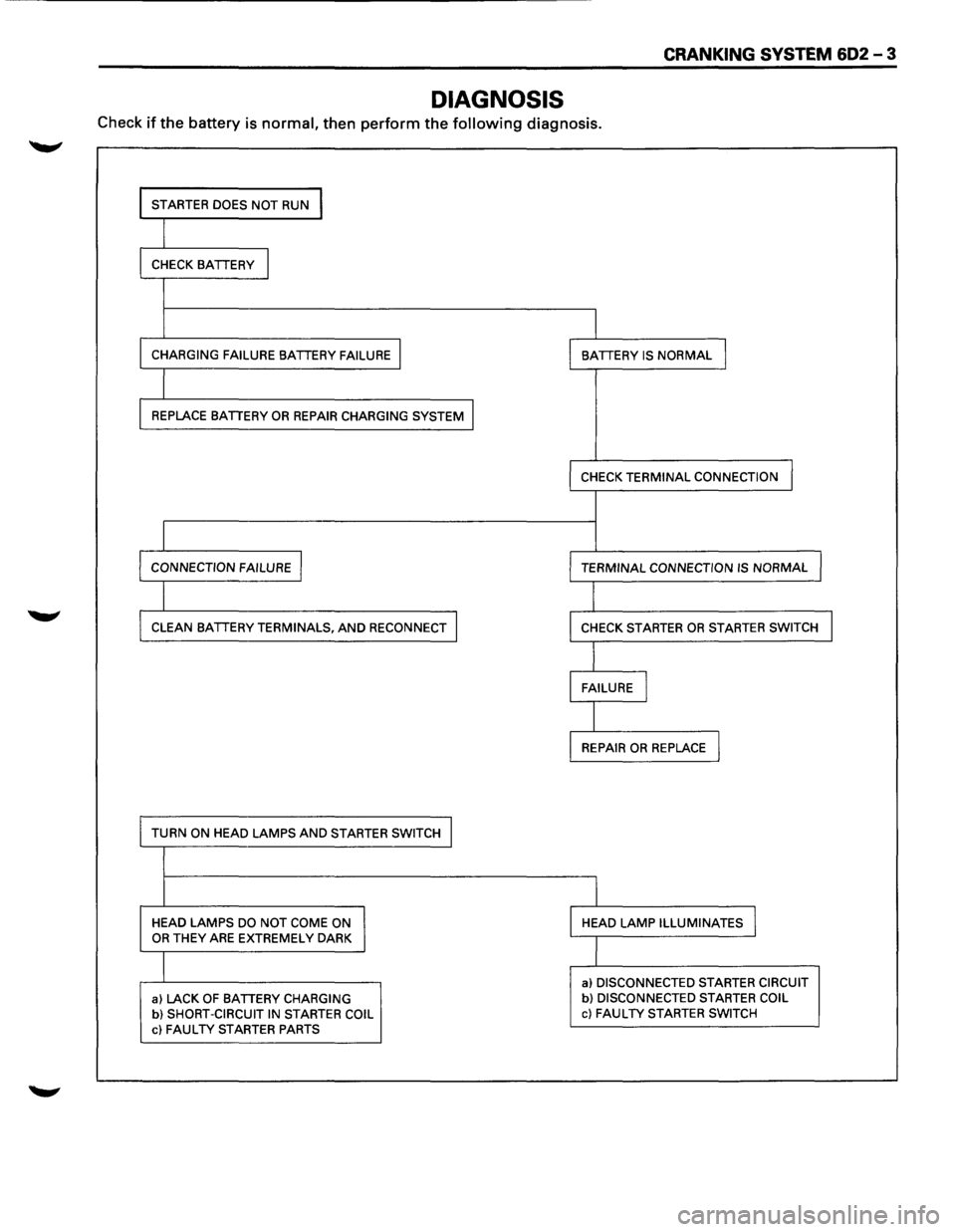
DIAGNOSIS
Check if the battery is normal, then perform the following diagnosis.
I STARTER DOES NOT RUN I
I CHECK BATTERY I
I
CHARGING FAILURE BATTERY FAILURE I I BATTERY IS NORMAL I
I REPLACE BATTERY OR REPAIR CHARGING SYSTEM I
I
CHECK TERMINAL CONNECTION
I CONNECTION FAILURE I I TERMINAL CONNECTION IS NORMAL J
I CLEAN BATTERY TERMINALS, AND RECONNECT I
I CHECK STARTER OR STARTER SWITCH I
I FAILURE I
I REPAIR OR REPLACE I
TURN ON HEAD LAMPS AND STARTER SWITCH I
I
HEAD LAMPS DO NOT COME ON HEAD LAMP ILLUMINATES I OR THEY ARE EXTREMELY DARK
I
a) DISCONNECTED STARTER CIRCUIT
a) LACK OF BATTERY CHARGING b) DISCONNECTED STARTER COIL
b) SHORT-CIRCUIT IN STARTER COIL c) FAULTY STARTER SWITCH
c) FAULTY STARTER PARTS
Page 663 of 1928
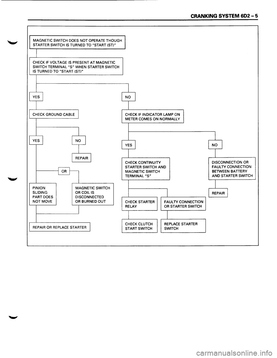
CRANKING SYSTEM 602-5
MAGNETIC SWITCH DOES NOT OPERATE THOUGH STARTER SWITCH IS TURNED TO "START (ST)"
CHECK IF VOLTAGE IS PRESENT AT MAGNETIC
SWITCH TERMINAL "S" WHEN STARTER SWITCH
IS TURNED TO "START (ST)"
YES
I NO I
CHECK GROUND CABLE I CHECK IF INDICATOR LAMP ON METER COMES ON NORMALLY
I
I
YES I NO I YES I I I
NO
I REPAIR I CHECK CONTINUITY DISCONNECTION OR
STARTER SWITCH AND FAULTY CONNECTION
OR MAGNETIC
SWITCH BETWEEN BATTERY
TERMINAL "S" AND STARTER SWITCH
I PINION
MAGNETIC SWITCH
SLIDING
OR COIL IS I REPAIR I PART DOES DISCONNECTED NOT MOVE OR BURNED OUT CHECK STARTER FAULTY CONNECTION
I
RELAY OR STARTER SWITCH
I
REPAIR OR REPLACE STARTER I CHECK CLUTCH REPLACE STARTER
START SWITCH SWITCH
Page 664 of 1928
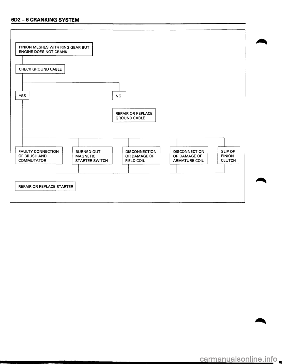
602-6 CRANKING SYSTEM
PINION MESHES WITH RING GEAR BUT ENGINE DOES NOT CRANK
CHECK
GROUND CABLE I
I
YES I NO I
I
REPAIR OR REPLACE I GROUND CABLE
I I I I
FAULTY CONNECTION BURNED-OUT DISCONNECTION DISCONNECTION SLIP OF OF BRUSH AND MAGNETIC OR DAMAGE OF OR DAMAGE OF PINION COMMUTATOR STARTER
SWITCH FIELD COIL ARMATURE COIL CLUTCH
I I I J
REPAIR OR REPLACE STARTER I
•
Page 672 of 1928
602-14 CRANKING SYSTEM
Fig. 602-23
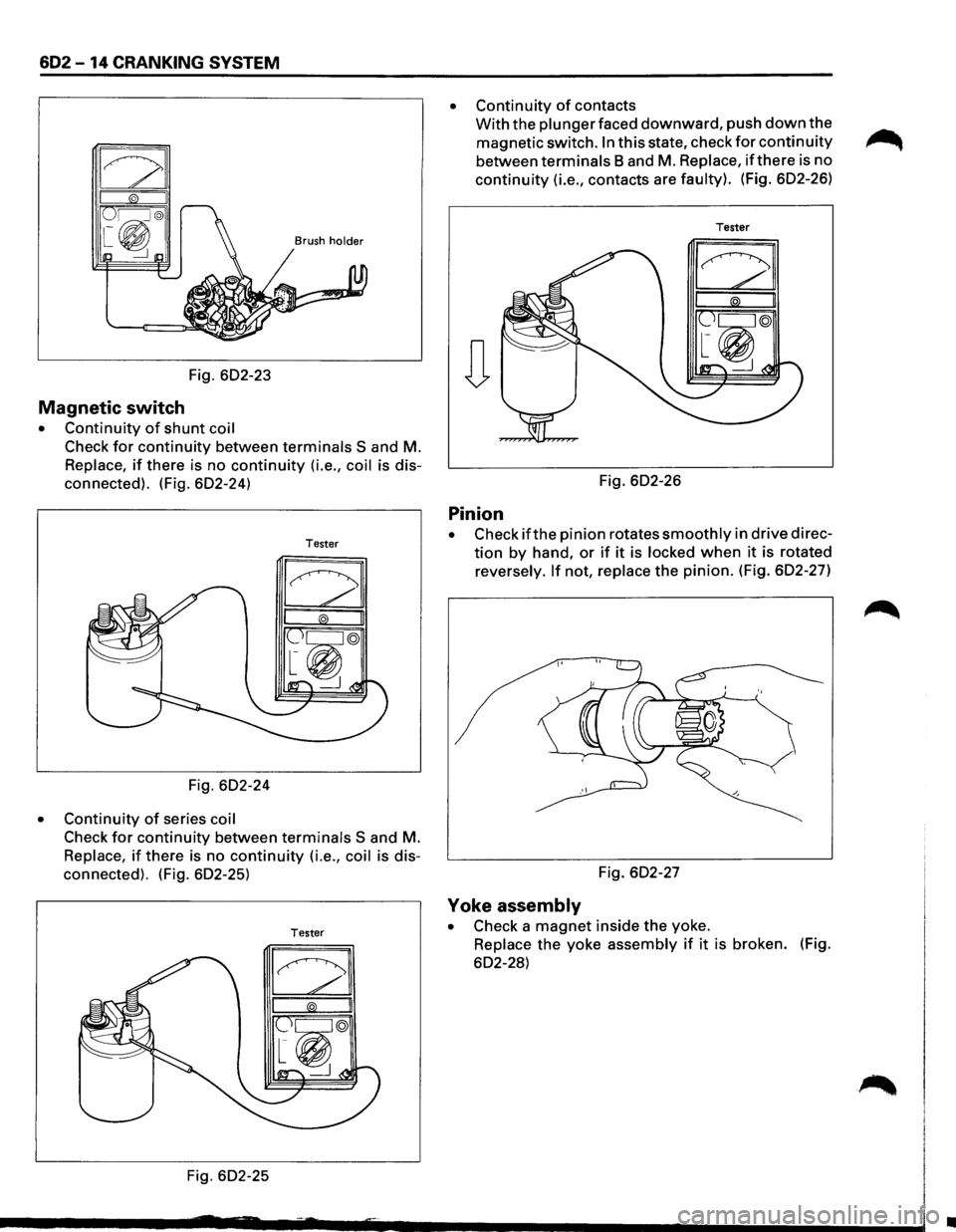
Magnetic switch
• Continuity of shunt coil
Check for continuity between terminals S and M.
Replace, if there is no continuity (i.e., coil is dis
connected). (Fig. 602-24)
Tester
Fig. 602-24
• Continuity of series coil
Check for continuity between terminals S and M.
Replace, if there is no continuity (i.e., coil is dis
connected). (Fig. 602-25)
Tester
Fig. 602-25
• Continuity of contacts
With the plunger faced downward, push down the
magnetic switch. In this state, check for continuity ~
between terminals Band M. Replace, if there is no
continuity (i.e., contacts are faulty). (Fig. 602-26)
Tester
Fig. 602-26
Pinion
• Check ifthe pinion rotates smoothly in drive direc
tion by hand, or if it is locked when it is rotated
reversely.
If not, replace the pinion. (Fig. 602-27)
Fig. 602-27
Yoke assembly
• Check a magnet inside the yoke.
Replace the yoke assembly if it is broken. (Fig.
602-28)
•
Page 685 of 1928
CHARGING SYSTEM 603 - 9
Fig. 603-19
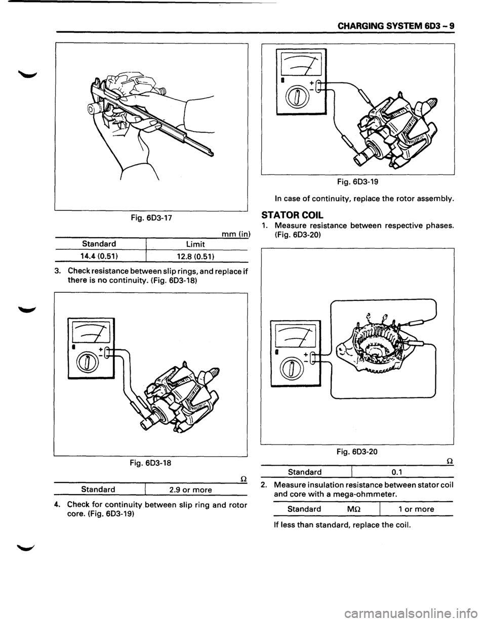
In case of continuity, replace the rotor assembly.
Fig. 603-17 STATOR COIL
1. Measure resistance between respective phases.
---------r-----:-:--:---'m;.;..;.;...;.m""'"(.....,..in) (Fig. 603-20)
limit Standard
14.4 (0.51)
12.8 (0.51)
3. Check resistance between slip rings, and replace if
there is no continuity. (Fig. 603-18)
Fig. 603-18
Standard 2.9
or more
4. Check for continuity between slip ring and rotor
core. (Fig. 603-19) Fig.
603-20
Standard
0.1
2. Measure insulation resistance between stator coil
and core with a mega-ohmmeter.
Standard
Mn 1 or more
If less than standard, replace the coil.
Page 691 of 1928
![ISUZU TROOPER 1995 Repair Manual IGNITION SYSTEM 604 - 3
ON-VEHICLE SERVICE
SPARK PLUG WIRES
EJ REMOVAL
Preparation
• Disconnect battery ground cable.
1. Spark plug wires (Fig. 604-2)
Fig. 6D4-2
(1!] INSPECTION AND REPAIR](/img/61/57183/w960_57183-690.png "ISUZU TROOPER 1995 Repair Manual IGNITION SYSTEM 604 - 3
ON-VEHICLE SERVICE
SPARK PLUG WIRES
EJ REMOVAL
Preparation
• Disconnect battery ground cable.
1. Spark plug wires (Fig. 604-2)
Fig. 6D4-2
(1!] INSPECTION AND REPAIR")
IGNITION SYSTEM 604 - 3
ON-VEHICLE SERVICE
SPARK PLUG WIRES
EJ REMOVAL
Preparation
• Disconnect battery ground cable.
1. Spark plug wires (Fig. 604-2)
Fig. 6D4-2
(1!] INSPECTION AND REPAIR
Check the high tension cable for insulation. Check
terminals for corrosion or damage, and replace as
necessary.
Measuring resistance of spark plug wires (kQ)
Spare plug wires SOHC DOHC
No.1 cable 6.4-14.9 6.2-14.2
No.2 cable 5.7-13.1 7.2-16.7
No.3 cable 6.2-14.4 6.5-14.9
No.4 cable 5.8-13.3 6.8-15.8
No.5 cable 6.4-14.9 6.9-16.0
No.6 cable 6.9-16.0 6.3-14.5
Measure resistance
of spark plug wires, and replace
the cable if its value exceeds the standard. (Fig. 6D4-
3)
Fig. 6D4-3
B INSTALLATION
1. Spark plug wires
• Connect ignition coils and spark plugs with
spark plug wires respectively. Match each
number (cylinder No.) marked on the ignition
coil with that on spark plug wire, and connect
each spark
plug for the cylinder. (Fig. 6D4-4)
LH bank
y Front
#4-
#1--
1®®®1
RH Bank
Connecting Position of Spark plug wire
Fig. 6D4-4
• Connect battery ground cable.
"f CAUTION
Do not cross, twist or pull the spark plug wires.
SPARK PLUG
EJ REMOVAL
1. Spare plug wires
2. Spark plugs (Fig. 604-5)
Page 692 of 1928
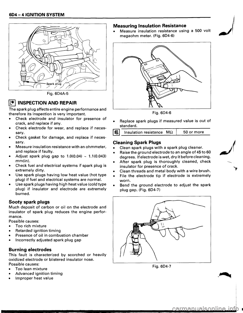
604-4 IGNITION SYSTEM
Fig. 604A-5
~ INSPECTION AND REPAIR
The spark plug affects entire engine performance and
therefore its inspection is very important.
• Check electrode and insulator for presence of
crack, and replace if any.
• Check electrode for wear, and replace if neces
sary.
• Check gasket for damage, and replace if neces
sary.
• Measure insulation resistance with an ohmmeter,
and replace if faulty.
• Adjust spark plug gap to 1.0(0.04) -1.1 (0.043)
mm(in).
• Check fuel and electrical systems if spark plug is
extremely dirty.
• Use spark plugs having low heat value (hot type
plug) if fuel and electrical systems are normal.
• Use spark plugs having high heat value (cold type
plug) if insulator and electrode are extremely
burned.
Sooty spark plugs
Much deposit of carbon or oil on the electrode and
insulator of spark plug reduces the engine perfor
mance.
Possible causes:
• Too rich mixture
• Retarded ignition timing
• Presence of oil in combustion chamber
• Incorrectly adjusted spark plug gap
Burning electrodes
This fault is characterized by scorched or heavily
oxidized electrode or blistered insulator nose.
Possible causes:
• Too lean mixture
• Advanced ignition timing
• Improper heat value
Measuring Insulation Resistance
• Measure insulation resistance using a 500 volt
megaohm meter. (Fig. 604-6)
Fig.
604-6
• Replace spark plugs if measured value is out of
standard.
I @!.j Insulation resistance MQ 50 or more
Cleaning Spark Plugs
• Clean spark plugs with a spark plug cleaner.
• Raise the ground electrode to an angle of 45 to 60
degrees. If electrode is wet, dry it before cleaning.
• After spark plug is thoroughly cleaned, check
insulator for presence of crack.
• Clean threads and metal body with a wire brush.
• File the electrode tip if electrode is extremely
worn.
• Bend the ground electrode to adjust the spark
plug gap. (Fig. 604-7)
Fig. 604-7
•