check oil ISUZU TROOPER 1995 Owner's Guide
[x] Cancel search | Manufacturer: ISUZU, Model Year: 1995, Model line: TROOPER, Model: ISUZU TROOPER 1995Pages: 1928
Page 500 of 1928
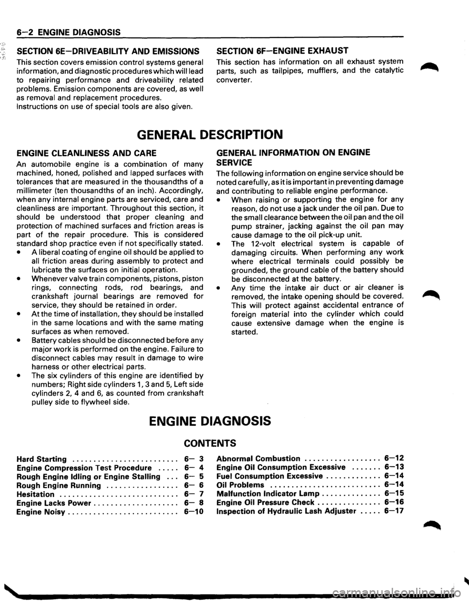
6-2 ENGINE DIAGNOSIS
SECTION 6E-DRIVEABILITY
AND EMISSIONS
This section covers emission control systems general
information, and diagnostic procedures which will lead
to repairing performance and driveability related
problems.
Emission components are covered, as well
as removal and replacement procedures.
Instructions on use
of special tools are also given.
SECTION 6F-ENGINE EXHAUST
This section has information on all exhaust system
parts, such
as tailpipes, mufflers, and the catalytic
converter.
GENERAL DESCRIPTION
ENGINE CLEANLINESS AND CARE
An automobile engine is a combination of many
machined, honed,
polished and lapped surfaces with
tolerances that are measured in the thousandths of a
millimeter (ten thousandths of an inch). Accordingly,
when any
internal engine parts are serviced, care and
cleanliness are important. Throughout this section, it
should be understood that proper cleaning and
protection
of machined surfaces and friction areas is
part
of the repair procedure. This is considered
standard shop practice even
if not specifically stated.
• A liberal coating of engine oil should be applied to
all friction areas during assembly to protect and
lubricate the surfaces on initial operation.
• Whenever valve train components, pistons, piston
rings, connecting rods, rod bearings, and
crankshaft
journal bearings are removed for
service, they should be retained in order.
• At the time of installation, they should be installed
in the same locations and with the same mating
surfaces
as when removed.
• Battery cables should be disconnected before any
major
work is performed on the engine. Failure to
disconnect
cables may result in damage to wire
harness
or other electrical parts.
• The six cylinders of this engine are identified by
numbers; Right side
cylinders 1, 3 and 5, Left side
cylinders 2, 4 and 6, as counted from crankshaft
pulley side to flywheel side.
GENERAL INFORMATION ON ENGINE
SERVICE
The following information on engine service should be
noted
carefully, as it is important in preventing damage
and contributing
to reliable engine performance.
• When raising or supporting the engine for any
reason,
do not use a jack under the oil pan. Due to
the
small clearance between the oil pan and the oil
pump strainer, jacking against the oil pan may
cause damage to the
oil pick-up unit.
• The 12-volt electrical system is capable of
damaging circuits. When performing any work
where electrical terminals could possibly be
grounded, the ground cable of the battery should
be disconnected at the battery.
• Any time the intake air duct or air cleaner is
removed, the intake opening
should be covered.
This
will protect against accidental entrance of
foreign material into the cylinder which could
cause extensive damage when the engine is
started.
ENGINE DIAGNOSIS
CONTENTS
Hard Starting . . . . . . . . . . . . . . . . . . . . . . . . . 6-3
Engine Compression
Test Procedure ..... 6-4
Rough Engine
Idling or Engine Stalling . . . 6-5
Rough Engine Running . . . . . . . . . . . . . . . . .
6-6
Hesitation . . . . . . . . . . . . . . . . . . . . . . . . . . . . 6-7
Engine Lacks
Power . . . . . . . . . . . . . . . . . . . . 6-8
Engine
Noisy .......................... 6-10
Abnormal Combustion . . . . . . . . . . . . . . . . . . 6-12
Engine Oil Consumption Excessive . . . . . . . 6-13
Fuel Consumption Excessive ............. 6-14
Oil Problems . . . . . . . . . . . . . . . . . . . . . . . . . . 6-14
Malfunction Indicator Lamp . . . . . . . . . . . . . . 6-15
Engine Oil Pressure Check ............... 6-16
Inspection of Hydraulic Lash Adjuster . . . . . 6-17
Page 501 of 1928
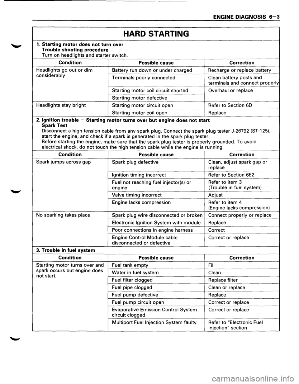
ENGINE DIAGNOSIS 6-3
HARD STARTING
1. Starting motor does not turn over
Trouble shooting procedure
Turn on headlights and starter switch.
Condition Possible cause Correction
Headlights go out or dim Battery run down or under charged Recharge or replace battery
considerably
Terminals poorly connected Clean battery posts and
terminals and connect properly
Starting motor coil circuit shorted Overhaul or replace
Starting motor defective
Headlights stay
bright Starting motor circuit open Refer to Section 6D
Starting
motor coil open Replace
2. Ignition trouble -Starting motor turns over but engine does not start
Spark Test
Disconnect a high tension cable from any spark plug. Connect the spark plug tester J-26792 (ST-1 25).
start the engine, and check if a spark is generated in the spark plug tester.
Before starting the engine, make sure
that the spark plug tester is properly grounded. To avoid
electrical shock, do not touch the high tension cable while the engine is running.
Condition Possible cause Correction
Spark jumps across gap
Spark plug defective Clean, adjust spark gap or
replace
Ignition
timing incorrect Refer to Section 6E2
Fuel not reaching fuel injector(s) or Refer to item 3
engine (Trouble
in
fuel system)
Valve
timing incorrect Adjust
Engine
lacks compression Refer to item 4
(Engine
lacks compression)
No sparking takes
place Spark plug wire disconnected or broken Connect properly or replace
Electronic Ignition System with module Replace
Poor connections in engine harness
Correct
Engine Control
Module cable Correct or replace
disconnected or defective
3. Trouble in fuel system
Condition Possible cause Correction
Starting motor turns over and
Fuel tank empty Fill
spark occurs but engine does
not start. Water in fuel system Clean
Fuel filter clogged Replace filter
Fuel pipe clogged Clean or replace
Fuel pump defective
Replace
Fuel
pump circuit open Correct or replace
Evaporative Emission Control System Correct or replace
circuit clogged
Multipart Fuel Injection System faulty Refer to "Electronic Fuel
Injection"
section
Page 502 of 1928
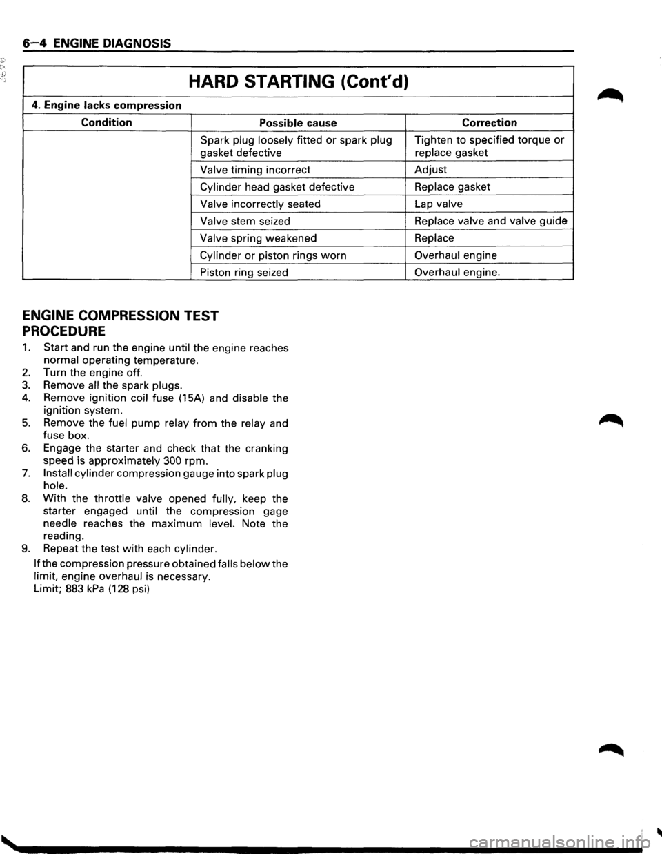
6-4 ENGINE DIAGNOSIS
HARD STARTING (Cont'd)
4. Engine lacks compression
Condition Possible cause
Spark plug loosely fitted or spark plug
gasket defective
Valve timing incorrect
Cylinder head gasket defective
Valve incorrectly seated
Valve stem seized
Valve spring weakened
Cylinder or piston rings worn
Piston ring seized
ENGINE COMPRESSION TEST
PROCEDURE
1. Start and run the engine until the engine reaches
normal operating temperature.
2. Turn the engine off.
3. Remove all the spark plugs.
4. Remove ignition coil fuse (15A) and disable the
ignition system.
5. Remove the fuel pump relay from the relay and
fuse box.
6. Engage the starter and check that the cranking
speed is approximately
300 rpm.
7. Install cylinder compression gauge into spark plug
hole.
8. With the throttle valve opened fully, keep the
starter engaged
until the compression gage
needle reaches the
maximum level. Note the
reading.
9. Repeat the test with each cylinder.
If
the compression pressure obtained falls below the
limit, engine overhaul is necessary.
Limit; 883
kPa (128 psi) Correction
Tighten
to specified torque or
replace gasket
Adjust
Replace gasket
Lap
valve
Replace valve
and valve guide
Replace
Overhaul engine
Overhaul engine.
Page 514 of 1928
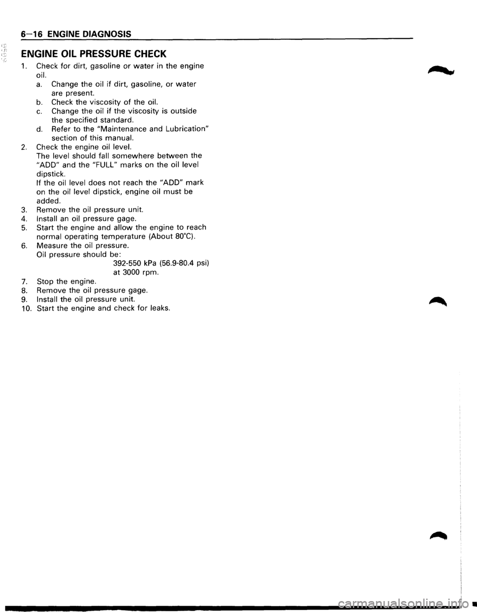
6-16 ENGINE DIAGNOSIS
ENGINE OIL PRESSURE CHECK
1. Check for dirt, gasoline or water in the engine
oil.
a. Change the oil if dirt, gasoline, or water
are present.
b. Check the viscosity of the oil.
c. Change the oil if the viscosity is outside
the specified standard.
d. Refer to the "Maintenance and Lubrication"
section of this manual.
2. Check the engine oil level.
The level should fall somewhere between the
"ADD" and the "FULL" marks on the oil level
dipstick.
If the oil level does not reach the "ADD" mark
on the
oil level dipstick, engine oil must be
added.
3. Remove the oil pressure unit.
4. Install an oil pressure gage.
5. Start the engine and allow the engine to reach
normal operating temperature (About 80°C).
6. Measure the oil pressure.
Oil pressure should be:
7. Stop the engine.
392-550 kPa (56.9-80.4 psi)
at
3000 rpm.
8. Remove the oil pressure gage.
9. Install the oil pressure unit.
10. Start the engine and check for leaks.
m ... cw
•
Page 522 of 1928
6A-6 GENERAL ENGINE MECHANICAL
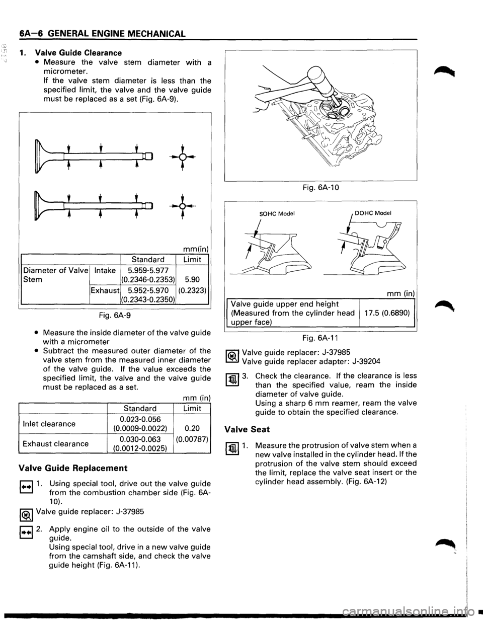
1. Valve Guide Clearance
• Measure the valve stem diameter with a
micrometer.
If the valve stem diameter is less than the
specified
limit, the valve and the valve guide
must be replaced as a set (Fig. 6A-9).
~
1: : !o:J
+
~ li : :~
+
mm(in)
Standard Limit
Diameter
of Valve Intake 5.959-5.977
Stem (0.2346-0.2353)
5.90
Exhaust 5.952-5.970 (0.2323)
(0.2343-0.2350)
Fig. 6A-9
• Measure
the inside diameter of the valve guide
with a micrometer
• Subtract the measured outer diameter of the
valve stem from the measured inner diameter
of the valve guide. If the value exceeds the
specified
limit, the valve and the valve guide
must be replaced as a set.
mm (in)
Standard Limit
Inlet
clearance 0.023-0.056
(0.0009-0.0022) 0.20
Exhaust clearance 0.030-0.063
(0.00787)
(0.0012-0.0025)
Valve Guide Replacement
r::l 1. Using special tool, drive out the valve guide
L::.l from the combustion chamber side (Fig. 6A-
10).
1®..1 Valve guide replacer: J-37985
1••12. Apply engine oil to the outside of the valve
guide.
Using
special tool, drive in a new valve guide
from the camshaft side, and check the valve
guide height (Fig. 6A-11 ).
Fig. 6A-1 0
SOHC Model
mm (in)
Valve guide upper end height
(Measured from the
cylinder head 17.5 (0.6890)
upper face)
Fig. 6A-11
li0\1 Valve guide replacer: J-37985
~ Valve guide replacer adapter: J-39204
~3. Check the clearance. If the clearance is less
than the specified value, ream the inside
diameter
of valve guide.
Using a sharp 6
mm reamer, ream the valve
guide to obtain the specified clearance.
Valve Seat
~1. Measure the protrusion of valve stem when a
new valve installed in the cylinder head. If the
protrusion
of the valve stem should exceed
the
limit, replace the valve seat insert or the
cylinder head assembly. (Fig. 6A-12)
•
Page 525 of 1928
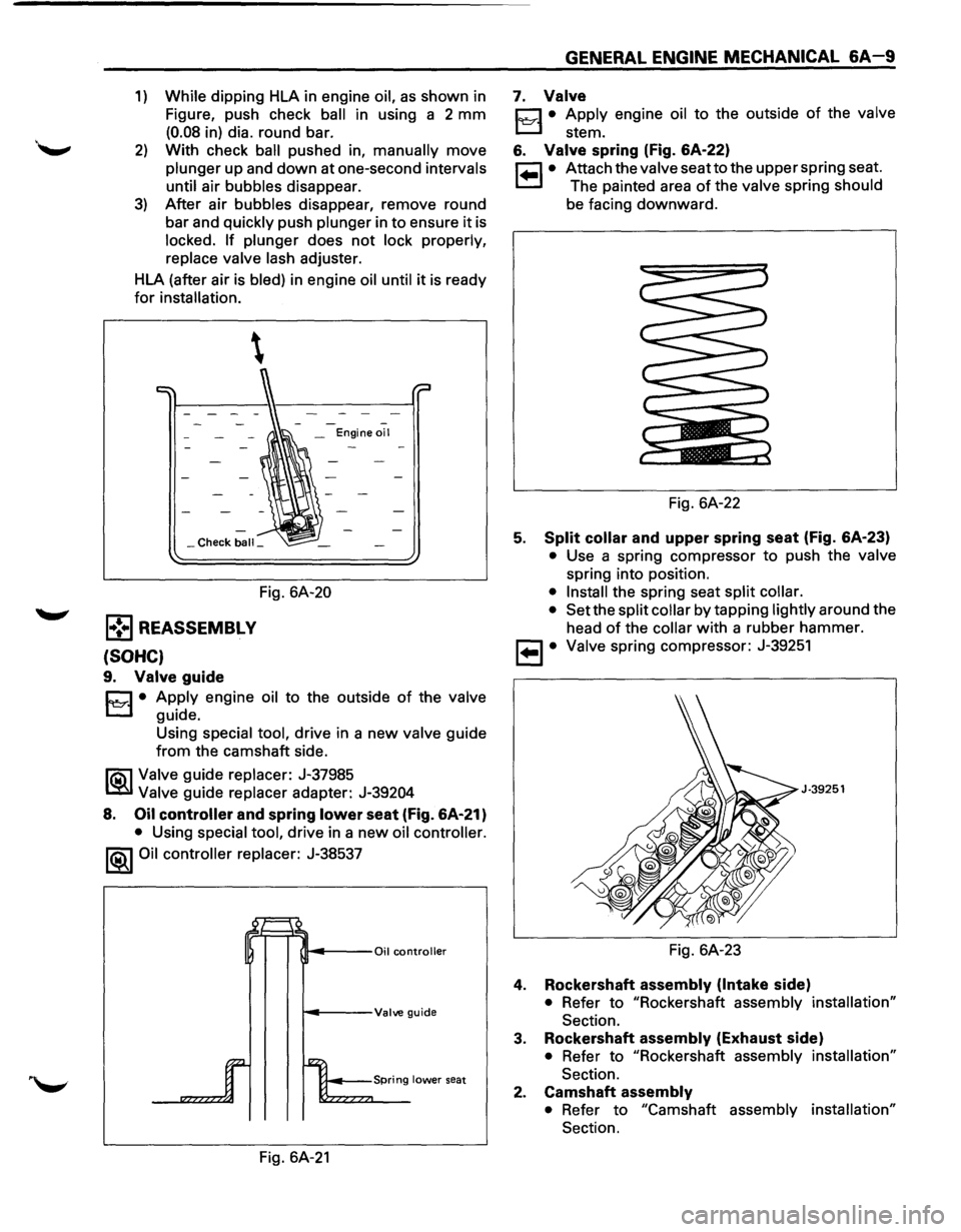
1) While dipping HLA in engine oil, as shown in
Figure, push check
ball in using a 2 mm
(0.08 in) dia. round bar.
2) With check ball pushed in, manually move
plunger up and down at one-second intervals
until
air bubbles disappear.
3) After air bubbles disappear, remove round
bar and
quickly push plunger in to ensure it is
locked. If plunger does not lock properly,
replace valve lash adjuster.
HLA (after air is
bled) in engine oil until it is ready
for installation.
-_ Engine oil
_Check ball_
Fig. 6A-20
l•!•l REASSEMBL V
(SOHC)
9. Valve guide
C1 • Apply engine oil to the outside of the valve
t..::::.l guide.
Using
special tool, drive in a new valve guide
from the camshaft side.
li5\l Valve guide replacer: J-37985
~ Valve guide replacer adapter: J-39204
8. Oil controller and spring lower seat (fig. 6A·21)
• Using special tool, drive in a new oil controller.
1®.1 Oil controller replacer: J-38537
~---Valve guide
Fig. 6A-21
GENERAL ENGINE MECHANICAL 6A-9
7. Valve
C1 • Apply engine oil to the outside of the valve
t..::::.l stem.
6. Valve spring (fig. 6A-22)
r=l • Attach the valve seatto the upper spring seat.
1.=.1 The painted area of the valve spring should
be facing downward.
Fig. 6A-22
5. Split collar and upper spring seat (Fig. 6A-23)
• Use a spring compressor to push the valve
spring into position.
• Install the spring seat split collar.
• Set
the split collar by tapping lightly around the
head
of the collar with a rubber hammer.
, ... ,. Valve spring compressor: J-39251
J·39251
Fig. 6A-23
4. Rockershaft assembly (Intake side)
• Refer to "Rockershaft assembly installation"
Section.
3. Rockershaft assembly (Exhaust side)
• Refer to "Rockershaft assembly installation"
Section.
2. Camshaft assembly
• Refer to "Camshaft assembly installation"
Section.
Page 536 of 1928
6A-20 GENERAL ENGINE MECHANICAL
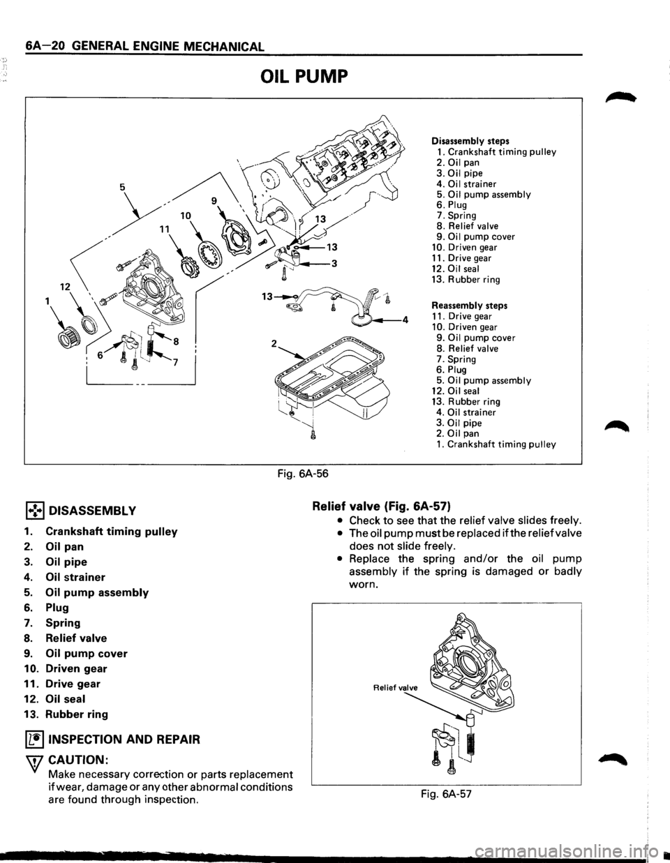
OIL PUMP
Fig. 6A-56
Disassembly steps 1. Crankshaft timing pulley 2. Oil pan 3. Oil pipe
4. Oi I strainer 5. Oil pump assembly 6. Plug 7. Spring
8. Relief valve 9. Oil pump cover 10. Driven gear 11. Drive gear 12. Oil seal 13. Rubber ring
Reassembly steps
11. Drive
gear 10. Driven gear 9. Oil pump cover
8. Relief valve 7. Spring
6. Plug 5. Oil pump assembly 12. Oil seal 13. Rubber ring
4. Oil strainer
3. Oil pipe 2. Oil pan 1. Crankshaft timing pulley
l•!•l DISASSEMBLY Relief
valve (Fig. 6A-57)
1. Crankshaft timing pulley
2. Oil pan
3. Oil pipe
4. Oil strainer
5. Oil pump assembly
6. Plug
7. Spring
8. Relief valve
9. Oil pump cover
10. Driven gear
11. Drive gear
12. Oil seal
13. Rubber ring
~ INSPECTION AND REPAIR
\fl CAUTION:
VI Make necessary correction or parts replacement
if wear, damage or any other abnormal conditions
are found through inspection.
• Check to see that the relief valve slides freely.
• The oil pump must be replaced ifthe relief valve
does
not slide freely.
• Replace the spring and/or the oil pump
assembly if the spring is damaged or badly
worn.
Fig. 6A-57
•
Page 537 of 1928
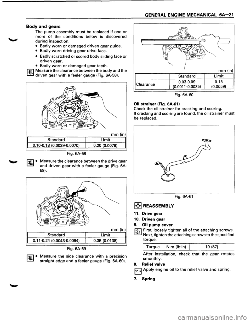
Body and gears
The pump assembly must be replaced if one or
more of the conditions below is discovered
during inspection.
• Badly worn or damaged driven gear guide.
• Badly worn driving gear drive face.
• Badly scratched or scored body sliding face or
driven gear.
• Badly worn or damaged gear teeth.
~ Measure the clearance between the body and the
I..!:.J driven gear with a feeler gauge (Fig. 6A-58).
mm (in)
Standard
Limit
0.10-0.18 (0.0039-0.0070) 0.20 (0.0079)
~·
Fig. 6A-58
Measure the
clearance between the drive gear
and driven gear
with a feeler gauge (Fig. 6A-
59).
mm (in)
Standard Limit
0.11-0.24
(0.0043-0.0094) 0.35 (0.0138)
Fig. 6A-59
ltm.l• Measure the side clearance with a precision
straight edge and a
feeler gauge (Fig. 6A-60).
GENERAL ENGINE MECHANICAL 6A-21
Clearance
Standard
0.03-0.09
(0.0011-0.0035)
Fig. 6A-60
Oil strainer (Fig. 6A-61)
mm (in)
Limit
0.15
(0.0059)
Check the
oil strainer for cracking and scoring.
If cracking and scoring are found, the oil strainer must
be replaced.
Fig. 6A-61
l•!•l REASSEMBLY
11. Drive gear
1
0. Driven gear
9. Oil pump cover
~ First, loosely tighten all of the attaching screws.
~ Next, tighten the attaching screws to the specified
torque.
Torque
N·m (lb·in) ) 10 (87)
After installation, check that the gear rotates
smoothly.
8. Relief valve
I~J Apply engine oil to the relief valve and spring.
7. Spring
Page 540 of 1928
6A-24 GENERAL ENGINE MECHANICAL
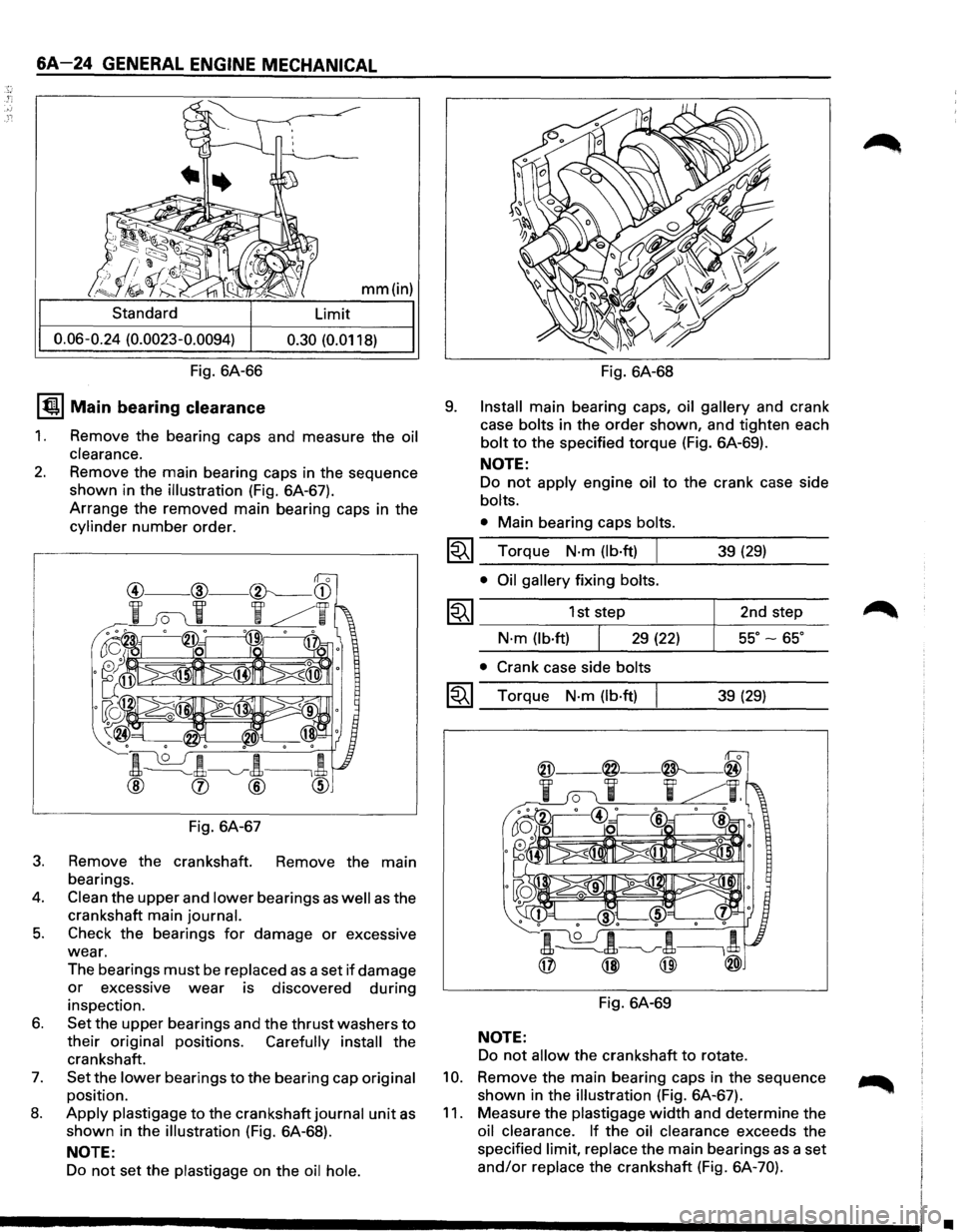
mm(in)
Standard Limit
0.06-0.24 (0.0023-0.0094) 0.30 (0.0118)
Fig. 6A-66 Fig. 6A-68
IQI Main bearing clearance
1. Remove the bearing caps and measure the oil
clearance.
2. Remove the main bearing caps in the sequence
shown in the
illustration (Fig. 6A-67).
Arrange the removed main bearing caps in the
cylinder number order.
Fig. 6A-67
3. Remove the crankshaft. Remove the main
bearings.
4. Clean the upper and lower bearings as well as the
crankshaft main
journal.
5. Check the bearings for damage or excessive
wear.
The bearings
must be replaced as a set if damage
or excessive wear is discovered during
inspection.
6. Set the upper bearings and the thrust washers to
their original positions. Carefully install the
crankshaft.
7. Set the lower bearings to the bearing cap original
position.
8. Apply plastigage to the crankshaft journal unit as
shown in the illustration (Fig. 6A-68).
NOTE:
Do not set the plastigage on the oil hole.
9. Install main bearing caps, oil gallery and crank
case
bolts in the order shown, and tighten each
bolt to the specified torque (Fig. 6A-69).
~
~
~
NOTE:
Do not apply engine oil to the crank case side
bolts.
•
Main bearing caps bolts.
Torque N·m (lb·ft) I 39 (29)
• Oil gallery fixing bolts.
1st step 2nd step
N·m (lb·ft) 29 (22) 55°-65°
• Crank case side bolts
Torque N·m (lb·ft) 39 (29)
Fig. 6A-69
NOTE:
Do not allow the crankshaft to rotate.
10. Remove the main bearing caps in the sequence
shown in the
illustration (Fig. 6A-67).
11. Measure the plastigage width and determine the
oil clearance. If the oil clearance exceeds the
specified
limit, replace the main bearings as a set
and/or replace the crankshaft (Fig. 6A-70).
•
Page 543 of 1928
l•!•l REASSEMBL V
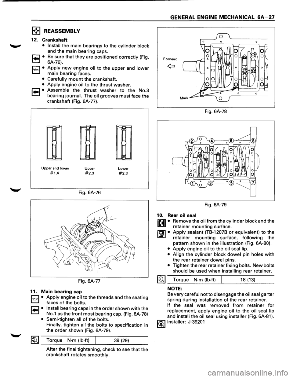
12. Crankshaft
• Install the main bearings to the cylinder block
and the main bearing caps.
1 .. 1• Be sure that they are positioned correctly (Fig.
6A-76).
1~1· Apply new engine oil to the upper and lower
main bearing faces.
• Carefully mount the crankshaft.
• Apply engine oil to the thrust washer.
1 .. 1• Assemble the thrust washer to the No.3
bearing
journal. The oil grooves must face the
crankshaft (Fig. 6A-77).
Upper and lower
#1.4
~
~
IH
t=
Upper
#2,3
Fig. 6A-76
Fig. 6A-77
11. Main bearing cap
Lower
#2,3
B • Apply engine oil to the
threads and the seating
' faces
of the bolts.
r=1 • Install bearing caps in the order shown with the
L:::.l No.1 as the front most bearing cap. (Fig. 6A-78)
• Semi-tighten all of the bolts.
Finally,
tighten all the bolts to specification in
the
order shown (Fig. 6A-79).
1~1 Torque N·m (lb·ft) 39 (29)
After the final tightening, check to see that the
crankshaft rotates
smoothly.
GENERAL ENGINE MECHANICAL 6A-27
Forward
Fig. 6A-78
Fig. 6A-79
10. Rear oil seal
liill • Re~ove the oil_from the cylinder block and the
U retainer mounting surface.
rEil • Apply sealant (TB-1207B or equivalen_t) to the
1.:::!!.1 retainer mounting surface, follow~ng the
pattern shown in the
illustration (Fig. 6A-80).
• Apply engine oil to the oil seal lip.
• Align
the cylinder block dowel pin holes with
the rear retainer dowel pins.
• Tighten the rear retainer fixing bolts. New bolts
should
be used when installing rear retainer.
~~~ Torque N·m (lb·ft) 18 (13)
NOTE:
Be very careful notto disengage the oil seal garter
spring during
installation of the rear retainer.
If the seal was removed from retainer for
replacement, apply engine oil to the oil seal lip
and install the oil seal using installer (Fig. 6A-81).
l®llnstaller: J-39201