fog light ISUZU TROOPER 1995 Service Manual
[x] Cancel search | Manufacturer: ISUZU, Model Year: 1995, Model line: TROOPER, Model: ISUZU TROOPER 1995Pages: 1928
Page 1620 of 1928
9B-36 CRUISE CONTROL
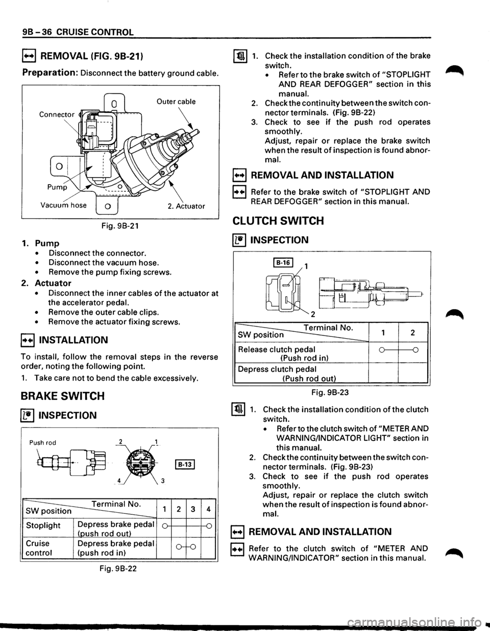
B REMOVAL (FIG. 98-21)
Preparation: Disconnect the battery ground cable.
Vacuum hose
Fig. 98-21
1. Pump
• Disconnect the connector.
• Disconnect the vacuum hose.
• Remove the pump fixing screws.
2. Actuator
• Disconnect the inner cables of the actuator at
the accelerator
pedal.
•
Remove the outer cable clips.
• Remove the actuator fixing screws.
E) INSTALLATION
To install, follow the removal steps in the reverse
order, noting
the following point.
1. Take care not to bend the cable excessively.
BRAKE SWITCH
~ INSPECTION
2 1
Push rod
~
~'
s ~ 1
Stoplight Depress brake pedal
(oush rod out)
Cruise Depress brake
pedal
control (push rod in)
Fig. 98-22
I B-131
2 3
o--o
4
~1. Check the installation condition of the brake
switch.
• Refer to the brake switch of "STOPLIGHT
AND REAR DEFOGGER" section in this
manual.
2. Check the continuity between the switch con
nector terminals. (Fig. 98-22)
3. Check to see if the push rod operates
smoothly. Adjust, repair
or replace the brake switch
when the result
of inspection is found abnor
mal.
B REMOVAL AND INSTALLATION
1·++·1 Refer to the brake switch of "STOPLIGHT AND
REAR DEFOGGER" section in this manual.
CLUTCH SWITCH
~INSPECTION
I B-161 1
rnll2a-~~
~ s 1 2
Release clutch pedal 0 ~ ~
(Push rod in)
Depress
clutch pedal
~1.
(Push rod out)
Fig. 98-23
Check the installation
condition of the clutch
switch.
• Refer to the clutch switch of "METER AND
WARNING/INDICATOR LIGHT" section in
this
manual.
2. Check the continuity between the switch con
nector terminals. (Fig. 98-23)
3. Check to see if the push rod operates
smoothly. Adjust, repair
or replace the clutch switch
when the result of inspection is found abnor
mal.
B REMOVAL AND INSTALLATION
1••1 Refer to the clutch switch of "METER AND ...-...
WARNING/INDICATOR"
section in this manual. ,...........
Page 1827 of 1928
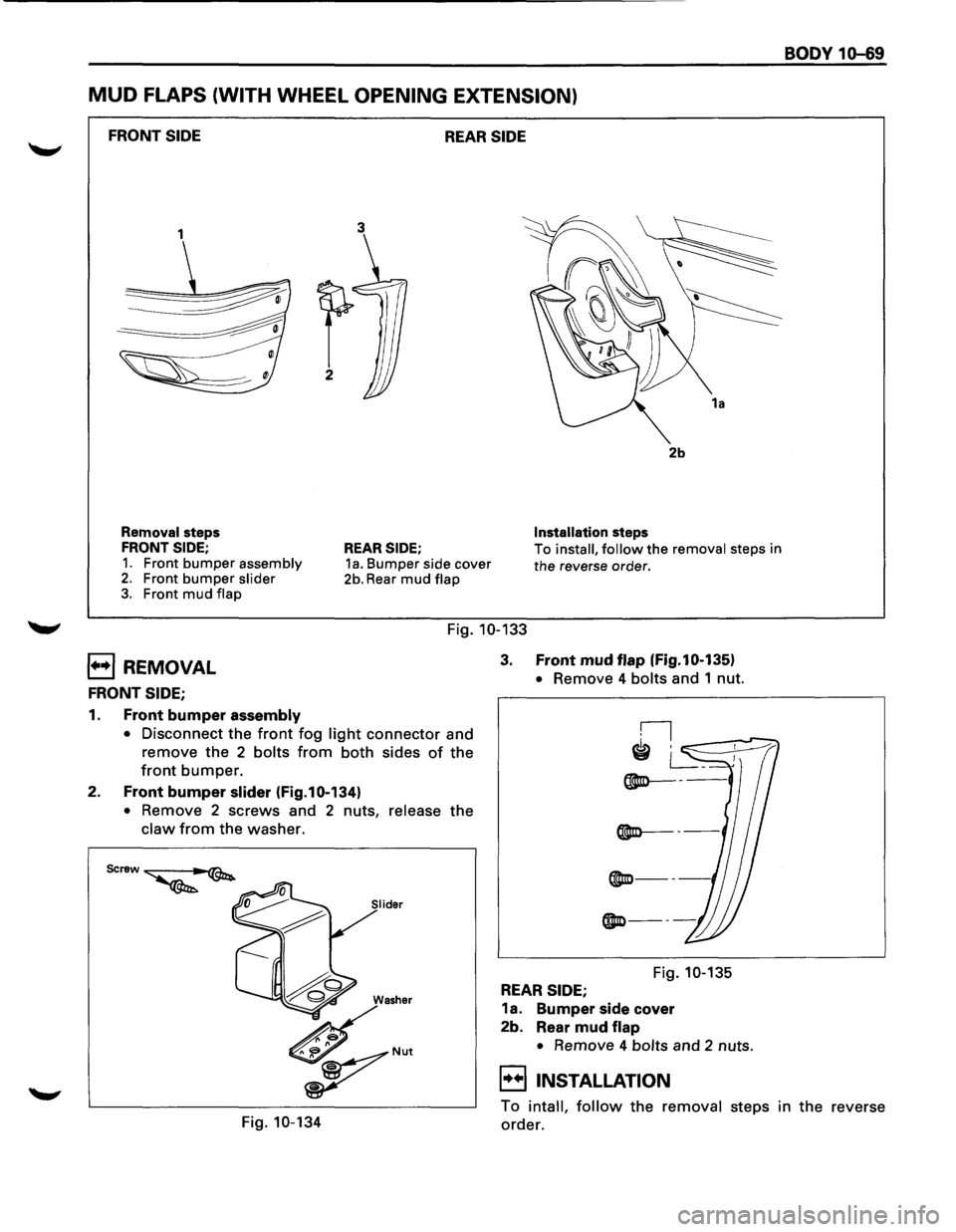
MUD FLAPS (WITH WHEEL OPENING EXTENSION)
FRONT SIDE REAR SIDE
1
Removal steps
FRONT SIDE;
1. Front bumper assembly 2. Front bumper slider 3. Front mud flap
3
REAR SIDE; 1a. Bumper side cover
2b. Rear mud flap
2b
Installation steps
To
install, follow the removal steps in
the reverse order.
Fig. 10-133
E) REMOVAL
FRONT SIDE;
1. Front bumper assembly
• Disconnect the front fog light connector and
remove the 2 bolts from both sides of the
front bumper.
2. Front bumper slider (Fig.10-134)
• Remove 2 screws and 2 nuts, release the
claw from the washer.
3. Front mud flap (Fig.10-135l
• Remove 4 bolts and 1 nut.
®Io---
Fig. 10-135
REAR SIDE;
1a. Bumper side cover
2b. Rear mud flap
• Remove 4 bolts and 2 nuts.
EIINSTALLATION
BODY 10-69
Fig. 10-134
To intall, follow the removal steps in the reverse
order.
Page 1840 of 1928
10-82 BODY
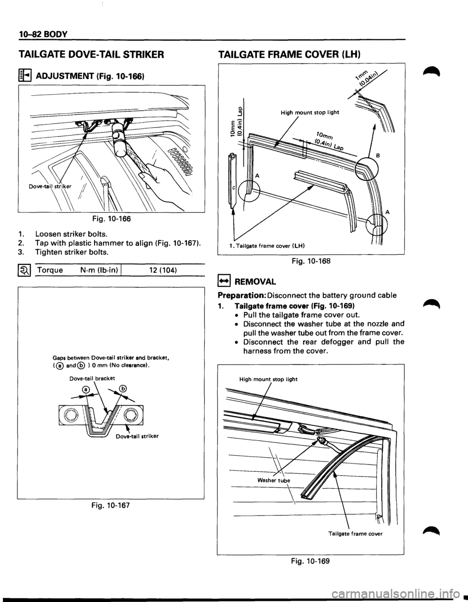
TAILGATE DOVE-TAIL STRIKER
I~FI ADJUSTMENT (Fig. 10-166)
Dove-tail striker 1/
\~!
Fig. 10-166
1. Loosen striker bolts.
2. Tap with plastic hammer to align (Fig. 10-167).
3. Tighten striker bolts.
~~~ Torque N·m (lb.in) I 12 (104)
Gaps between Dove-tail striker and bracket,
!@and@ ) 0 mm (No clearance).
Dove-tail bracket
Fig. 10-167
TAILGATE FRAME COVER (LH)
0. j High mount stop light
1. Tailgate frame cover (LH)
Fig. 10-168
1+•1 REMOVAL
Preparation:
Disconnect the battery ground cable
1. Tailgate frame cover (Fig. 10-169}
• Pull the tailgate frame cover out.
• Disconnect the washer tube at the nozzle and
pull the washer tube out from the frame cover.
• Disconnect the rear defogger and pull the
harness
from the cover.
High mount stop light
Tailgate frame cover
Fig. 10-169
•