air filter ISUZU TROOPER 1995 Workshop Manual
[x] Cancel search | Manufacturer: ISUZU, Model Year: 1995, Model line: TROOPER, Model: ISUZU TROOPER 1995Pages: 1928
Page 6 of 1928
OA-2 GENERAL INFORMATION
1.
2.
3.
HOW TO USE THE MANUAL
Find the applicable section by referring to the
table
of contents.
4. In the beginning of each section (with the de
scription
of service operations between them,
as a rule), the General Description and the
Diagnosis give
information for the related
malfunctions and diagnosis. And, in the
following portion, the service data or the special
tools necessary
for the service operations of the
section are gathered together under
"Main Data
and
Specifications" and the "Special Tools", for
at-a-glance reference.
Each
section is basically arranged in the
following order headin~:
General description
Diagnosis
On-vehicle service
Unit repair
Main data and specifications
Special tools
The service operations are in
two groups: one is
the
"On-vehicle service" where operations can
be directly performed on the vehicle, and the
other is
the "Unit repair" where the operations
are done on the
work bench after removing the
unit
from the vehicle.
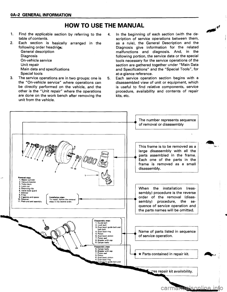
5. Each service operation section begins with a
disassembled
view of unit or equipment, which
is useful
to find relative components, service
procedure, availability and contents
of repair
kits, etc.
,..---------------------------+--e The number represents sequence of removal or disassembly
Removal steps 1. Master cylinder 2. Vacuum booster 3. Yoke clevis 4. Lock nut 5. Retaining clip 6. Valve body guard 7. Silencer 8. Filter 9. 2 gaskets and spacer 10. Retainer 11. Plate and seal assembly (
Installation steps To install, follow the remo ... al steps in the reverse order.
Disassembly steps 1. Guide bolt 2. Lock bolt 3. Dust boot; guide bolt and lock bolt 4. Dust boot ring
5. Piston 6. Dust boot; piston
7. Piston seal B. Bleeder with cap 9. Caliper body
Reassembly steps 9. Caliper body 8. Bleeder with cap 7. Piston seal 5. Piston 6. Dust boot; piston 4. Dust boot ring nust •"·•t; guide bolt and
This frame is to be removed as a
large disassembly
with all the
parts assembled in the frame.
Each one
of the parts in the
frame is removed as a small
disassembly.
When the installation (reas
sembly) procedure is the reverse
order of the removal (disas
sembly) procedure, the se
quence
of service operation and
the parts names
will be omitted.
Name
of parts listed in sequence
of service operation.
* Parts contained in repair kit.
•
-
.,... .
Page 18 of 1928
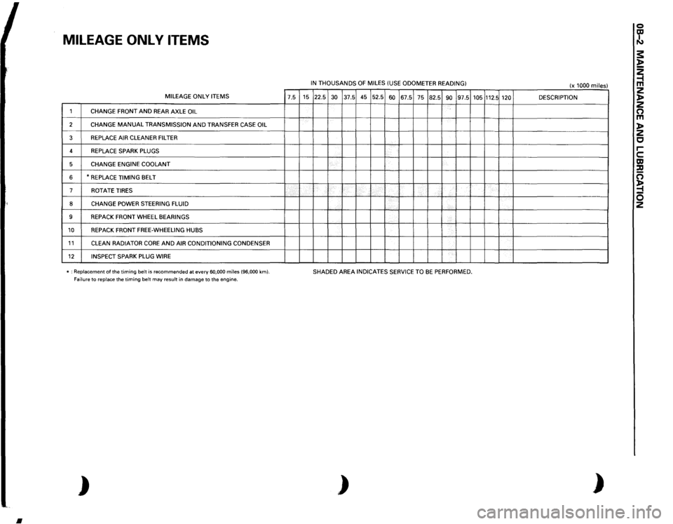
MILEAGE
ONL
V
ITEMS MILEAGE
ONLY
ITEMS
7.5
1
CHANGE
FRONT
AND
REAR AXLE
OIL
2
CHANGE
MANUAL
TRANSMISSION
AND
TRANSFER CASE
OIL
3
REPLACE AIR
CLEANER FILTER
4
REPLACE SPARK PLUGS
5
CHANGE ENGINE
COOLANT
6
*REPLACE
TIMING
BELT
7
ROT
ATE
TIRES
8
CHANGE
POWER STEERING FLUID
9
REPACK FRONT
WHEEL
BEARINGS
10
REPACK FRONT
FREE-WHEELING HUBS
11
CLEAN
RADIATOR
CORE
AND
AIR CONDITIONING CONDENSER
12
INSPECT SPARK PLUG WIRE
'
-----
* : Replacement
of the
timing
belt
is recommended
at every
60,000
miles
(96,000
km).
Failure
to replace
the timing
belt
may
result
in damage to the engine.
)
•
IN THOUSANDS
OF
MILES
(USE
ODOMETER
READING)
15 22.5
30
37.5 45 52.5
60
67.5
75
82.5
90
97.5
'
-
'---
~--·-L....
SHADED AREA
INDICATES SERVICE TO
BE
PERFORMED.
)
105
112.5
120 '-------
(x 1000
miles)
DESCRIPTION ------
)
0 ~ s: l> ~ z l> z 0 m l> z c rc m :a c; ~ 0 2
Page 21 of 1928
FLUID LEVEL CHECK
A fluid loss in any system (except windshield
washer) may indicate a problem. Repair the system
at once.
Engine
oil level -Check level and add if
necessary. The best time to check the engine oil
level is
when the oil is warm. After stopping the
engine with the vehicle on a level surface, wait a
few minutes for the oil to drain back to the oil pan.
Pull
out the oil level indicator (dipstick). Wipe it
clean and push the oil level indicator back down all
the
way. Pull out the oil level indicator, keeping the
tip down, and look at the oil level on it.
Add oil, if needed, to keep the oil level above
the
"ADD" mark and between the "ADD" and
"FULL" marks in the operating range area. Avoid
overfilling the engine since this may cause engine
damage. Push
the oil level indicator back down all
the
way after taking the reading.
If you check the oil level when the oil is cold, do
not run the engine first. The cold oil will not drain
back
to the pan fast enough to give a true oil level.
Engine coolant level and condition -Check
engine coolant level in the coolant reservoir and
add engine
coolant if necessary. Inspect the engine
coolant and replace it if dirty or rusty.
Windshield washer fluid level -Check washer
fluid level in reservoir and add if necessary.
Power steering system reservoir level-Check
and keep at
proper level.
Brake master cylinder reservoir level -Check
fluid. Keep fluid at proper level. A low fluid level
can indicate
worn disc brake pads which may need
to be serviced.
Hydraulic clutch system -Check fluid l~vel in
the reservoir.
Add fluid as required.
Battery fluid level -Check fluid level in the
battery.
FLUID LEAK CHECK
Check for fuel, water, oil or other fluid leaks by
looking at the surface beneath the vehicle after it
has been parked for a while. Water dripping from
the air conditioning system after use is normal. If
you notice gasoline fumes or fluid at any time,
locate the source and correct it at once.
ENGINE OIL AND OIL FILTER
REPLACEMENT
Always use API SE, SF, SG, SH or ILSAC GF-1
quality oils of the proper viscosity.
When choosing an oil, consider the range of
temperatures the car will be operated in before the
next oil change. Then, select the recommended oil
viscosity
from the chart (Fig. OB-1).
Always change the oil and the oil filter as soon as
possible after driving in a dust storm.
MAINTENANCE AND LUBRICATION OB-5
ENGINE COOLING SYSTEM INSPECTION
Inspect coolant/anti-freeze. If coolant is dirty or
rusty, drain, flush and refill with new coolant. Keep
coolant at the proper mixture for proper freeze
protection,
corrosion inhibitor level and best engine
operating temperature.
Inspect hoses and replace if
cracked, swollen or deteriorated. Tighten hose
clamps if equipped with screw-type clamps. Clean
outside of radiator and air conditioning condenser.
Wash
filler cap and neck. To help ensure proper
operation, a pressure test of both the cooling
system and cap is also recommended.
EXHAUST SYSTEM INSPECTION
Visually inspect the exhaust pipes, muffler, heat
shields and hangers
for cracks, deterioration, or
damage.
Be alert to any changes in the sound of the exhaust
system
or any smell of fumes. These are signs the
system may be leaking or overheating. Repair the
system at once,
if these conditions exist. (See also
"Engine Exhaust Gas Safety" and "Three Way
Catalytic Converter" in Owner's manual.)
FUEL CAP, FUEL LINES, AND FUEL TANK
INSPECTION
Inspect the fuel tank, the fuel cap and the fuel lines
every
60,000 miles (96,000 km) for damage which
could cause leakage.
Inspect the fuel cap and the gasket for correct sealing
and physical damage. Replace any damaged parts.
DRIVE BELT INSPECTION
Check the belts driving the steering oil pump, the air
conditioning compressor, and the generator
for
cracks, fraying, wear, and correct tension every 30,000
miles (48,000 km). Adjust or replace as necessary.
WHEEL ALIGNMENT, BALANCE AND
TIRES OPERATION
Uneven or abnormal tire wear, or a pull right or left
on a straight and level road may show the need for
a wheel alignment. A vibration of the steering
wheel or seat at normal highway speeds means a
wheel balancing is needed. Check tire pressure
when the tires are "cold" (include the spare).
Maintain pressure as shown in the tire placard,
which is located on the driver's door lock pillar.
STEERING SYSTEM OPERATION
Be alert for any changes in steering action. An
inspection
or service is needed when the steering
wheel is harder
to turn or has too much free play, or
if there are unusual sounds when turning or parking.
Page 22 of 1928
OB-6 MAINTENANCE AND LUBRICATION
BRAKE SYSTEMS OPERATION
Watch for the "BRAKE" light coming on. Other
signs of possible brake trouble are such things as
repeated pulling to one side when braking, unusual
sounds
when braking or between brake
applications,
or increased brake pedal travel. If you
note one of these conditions, repair the system at
once.
For convenience, the
following should be done
when wheels are removed for rotation: Inspect lines
and hoses
for proper hookup, bindings, leaks, crack,
chafing etc.
Inspect disc brake pads for wear and
rotors
for surface condition.
Inspect other brake parts, including parking brake
drums, linings etc., at the same time. Check parking
brake adjustment.
Inspect brakes more often if habit or
conditions
result in frequent braking.
PARKING BRAKE AND TRANSMISSION
PARK MECHANISM OPERATION
Park on a fairly steep hill and hold the vehicle with
the parking brake only. This checks holding ability.
On
automatic transmission vehicles, shifting from
"P" position to the other positions cannot be made
unless
the brake pedal is depressed when the key
switch is in
"ON" position or the engine running.
WARNING
•
Before checking starter safety switch
operation below,
be sure to have enough
room around the
vehicle. Then firmly apply
both the parking brake and the regular brake.
Do not
use the accelerator pedal. If the engine
starts, be ready
to turn off the key promptly.
Take these precautions because the vehicle
could move
without warning and possibly
cause personal injury
or property damage.
STARTER SAFETY SWITCH OPERATION
(AUTOMATIC TRANSMISSION)
Check by trying to start the engine in each gear
while setting the parking brake and the foot brake.
The starter
should crank only in "P" (Park) or "N"
(Neutral).
STARTER SAFETY SWITCH OPERATION
(MANUAL TRANSMISSION)
To check, place the shift lever in "Neutral", push
the clutch pedal halfway and try to start. The starter
should not crank. The starter should crank only
when the clutch pedal is fully depressed.
ACCELERATOR LINKAGE LUBRICATION
Lubricate the accelerator pedal fulcrum pin with
chassis grease.
STEERING AND SUSPENSION
INSPECTION
Inspect front and rear suspension and steering
system
for damaged, loose or missing parts or signs
of wear. Inspect power steering lines and hoses for
proper hookup, binding, leaks, cracks, chafing, etc.
BODY AND CHASSIS LUBRICATION
Lubricate the key lock cylinders, the hood latch, the
hood and door hinges, the door check link, the
parking cable guides,
the underbody contact points,
and the linkage.
PROPELLER SHAFT INSPECTION AND
LUBRICATION
Lubricate sliding yoke and universal joints with
grease containing MOS2 (disulfide molybdenum
type grease) at the interval shown in the
Maintenance Schedule. Check for play in normal
direction of rotation of sliding yoke and universal
joints. Also check
propeller shaft flange-to-pinion
bolts for proper torque of 63 N·m (46 lb·ft) for front
and rear propeller shaft.
AUTOMATIC TRANSMISSION FLUID
INSPECTION
Check the lubricant level every 7,500 miles (12,000
km) and add lubricant
if necessary.
Under harsh operating conditions, such as constant
driving in heavy city traffic during
hot weather, or in
hilly or mountainous terrain, change the transmission
fluid and service the
sump filter after every 20,000
miles (32,000 km) of operation.
AUTO CRUISE CONTROL INSPECTION
Check to see if the clearance between cruise link and
accelerator is normal. Also check that the vacuum
hoses are routed and connected properly.
CLUTCH LINES AND HOSES INSPECTION
Check lines and hoses for proper attachment,
binding, leaks, cracks, chafing, deterioration, etc.
Any questionable parts should be replaced or
repaired at once. When abrasion or wear is evident
on lines or hoses, the cause must be corrected.
..
Page 29 of 1928
MAINTENANCE AND LUBRICATION OB-13
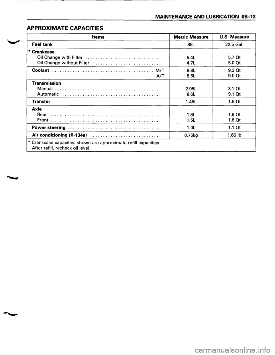
APPROXIMATE CAPACITIES
Items Metric Measure U.S. Measure
Fuel tank 85L 22.5 Gal.
*Crankcase
Oil Change with Filter .............................. 5.4L 5.7 at
Oil Change without Filter ••••••••••••••••••\
0 •••• 0 ••• 4.7L
5.0 at
Coolant ........................................ MIT 8.8L 9.3 at
A/T 8.5L 9.0 at
Transmission
Manual
.......................................... 2.95L 3.1 at
Automatic ••••••••••••••••••\
•• 0 •••• 0 0 0 ••••••••••• 8.6L 9.1 at
Transfer
1.45L 1.5 at
Axle
Rear o o o 0
0 0 0 0 0 0 0 0 0 0 0 0 0 0 0 0 I 0 0 0 o o o o o o o 0 0 0 0 0 0 0 0 0 0 0 o o 1.8L 1.9 at
Front ........................................ ~ ... 1.5L 1.6 at
Power steering ••• 0 ••••••••• 0 ••••••••••••••••••\
0 •••• 1.0L 1.1 at
Air conditioning (R-134a) o o 0
0 0 0 0 0 0 0 0 I 0 0 0 0 0 o o 0 o 0 0 0 0 0 0 0 0.75kg 1.651b
* Crankcase capacities shown are approximate refill capacities.
After
refill, recheck oil level.
Page 58 of 1928
1 B - 4 AIR CONDITIONING
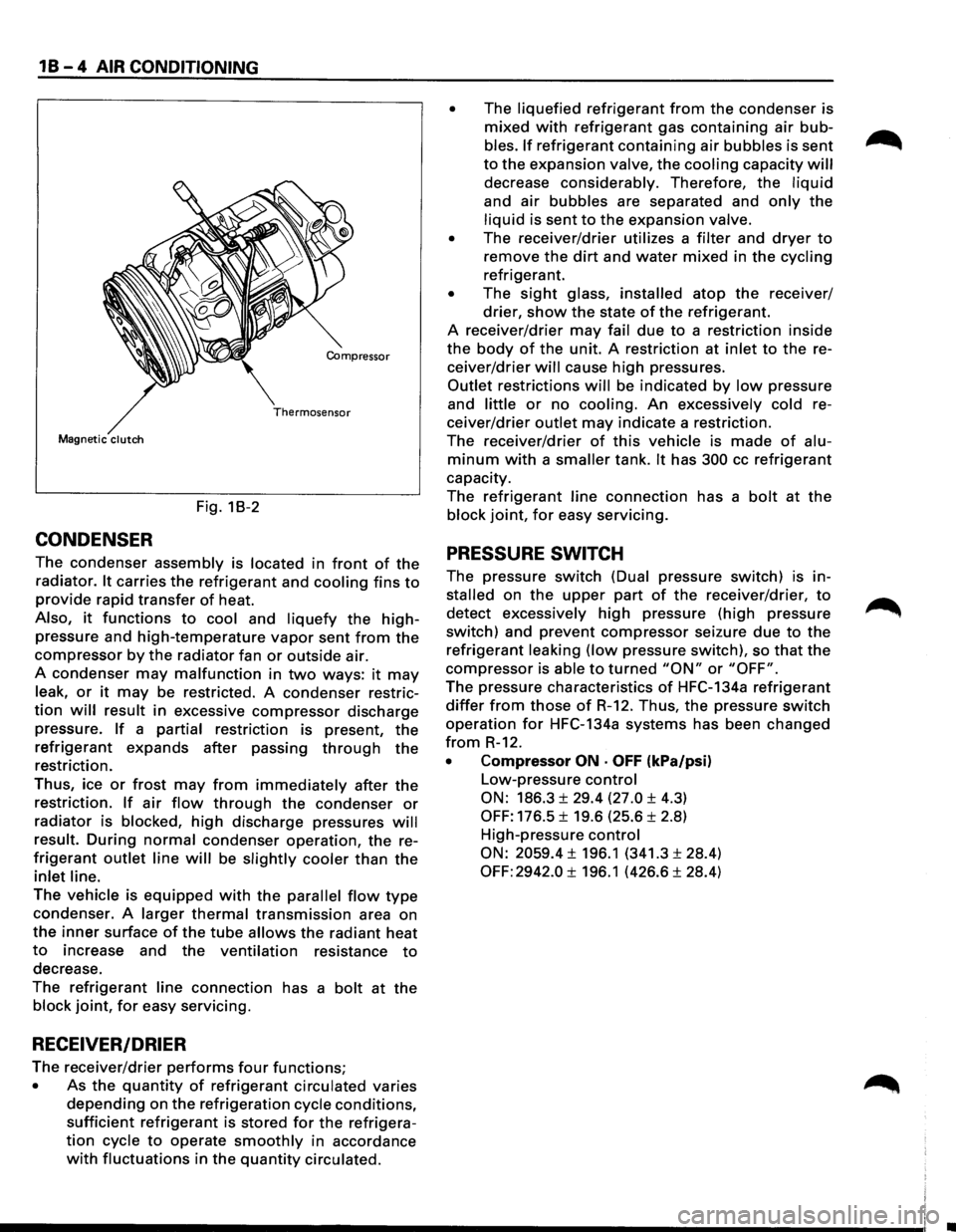
Compressor
Thermosensor
Magnetic clutch
Fig. 18-2
CONDENSER
The condenser assembly is located in front of the
radiator. It carries the refrigerant and cooling fins to
provide rapid transfer of heat.
Also, it functions to cool and liquefy the high
pressure and high-temperature vapor sent from the
compressor by the radiator fan or outside air.
A condenser
may malfunction in two ways: it may
leak, or it may be restricted. A condenser restric
tion will result in excessive compressor discharge
pressure.
If a partial restriction is present, the
refrigerant expands after passing through the
restriction.
Thus, ice
or frost may from immediately after the
restriction. If air flow through the condenser or
radiator is blocked, high discharge pressures will
result. During normal condenser operation, the re
frigerant outlet line will be slightly cooler than the
inlet line.
The vehicle is equipped with the parallel flow type
condenser. A larger thermal transmission area on
the inner surface of the tube allows the radiant heat
to increase and the ventilation resistance to
decrease.
The
refrigerant line connection has a bolt at the
block joint, for easy servicing.
RECEIVER/DRIER
The receiver/drier performs four functions;
• As the quantity of refrigerant circulated varies
depending on the refrigeration cycle conditions,
sufficient refrigerant is stored for the refrigera
tion cycle to operate smoothly in accordance
with fluctuations in the quantity circulated. •
The liquefied refrigerant from the condenser
is
mixed with refrigerant gas containing air bub
bles. If refrigerant containing air bubbles is sent
to the expansion valve, the cooling capacity will
decrease considerably. Therefore, the liquid
and air bubbles are separated and only the
liquid is sent to the expansion valve.
•
The receiver/drier utilizes a filter and dryer to
remove the dirt and water mixed in the cycling
refrigerant.
• The sight glass, installed atop the receiver/
drier, show the state of the refrigerant.
A receiver/drier may fail due to a restriction inside
the body of the unit. A restriction at inlet to the re
ceiver/drier
will cause high pressures.
Outlet restrictions will be indicated by low pressure
and
little or no cooling. An excessively cold re
ceiver/drier
outlet may indicate a restriction.
The receiver/drier
of this vehicle is made of alu
minum with a smaller tank. It has 300 cc refrigerant
capacity.
The
refrigerant line connection has a bolt at the
block joint, for easy servicing.
PRESSURE SWITCH
The pressure switch (Dual pressure switch) is in
stalled on the upper part of the receiver/drier, to
detect excessively high pressure (high pressure
switch) and prevent compressor seizure due to the
refrigerant leaking (low pressure switch), so that the
compressor is able to turned "ON" or "OFF".
The pressure characteristics of HFC-134a refrigerant
differ from those of R-12. Thus, the pressure switch
operation for HFC-134a systems has been changed
from R-12.
• Compressor ON · OFF (kPa/psi)
Low-pressure control
ON: 186.3 ± 29.4 (27.0 ± 4.3)
OFF: 176.5 ± 19.6 (25.6 ± 2.8)
High-pressure
control
ON: 2059.4 ± 196.1 (341.3 ± 28.4)
OFF: 2942.0 ± 196.1 (426.6 ± 28.4)
Page 347 of 1928
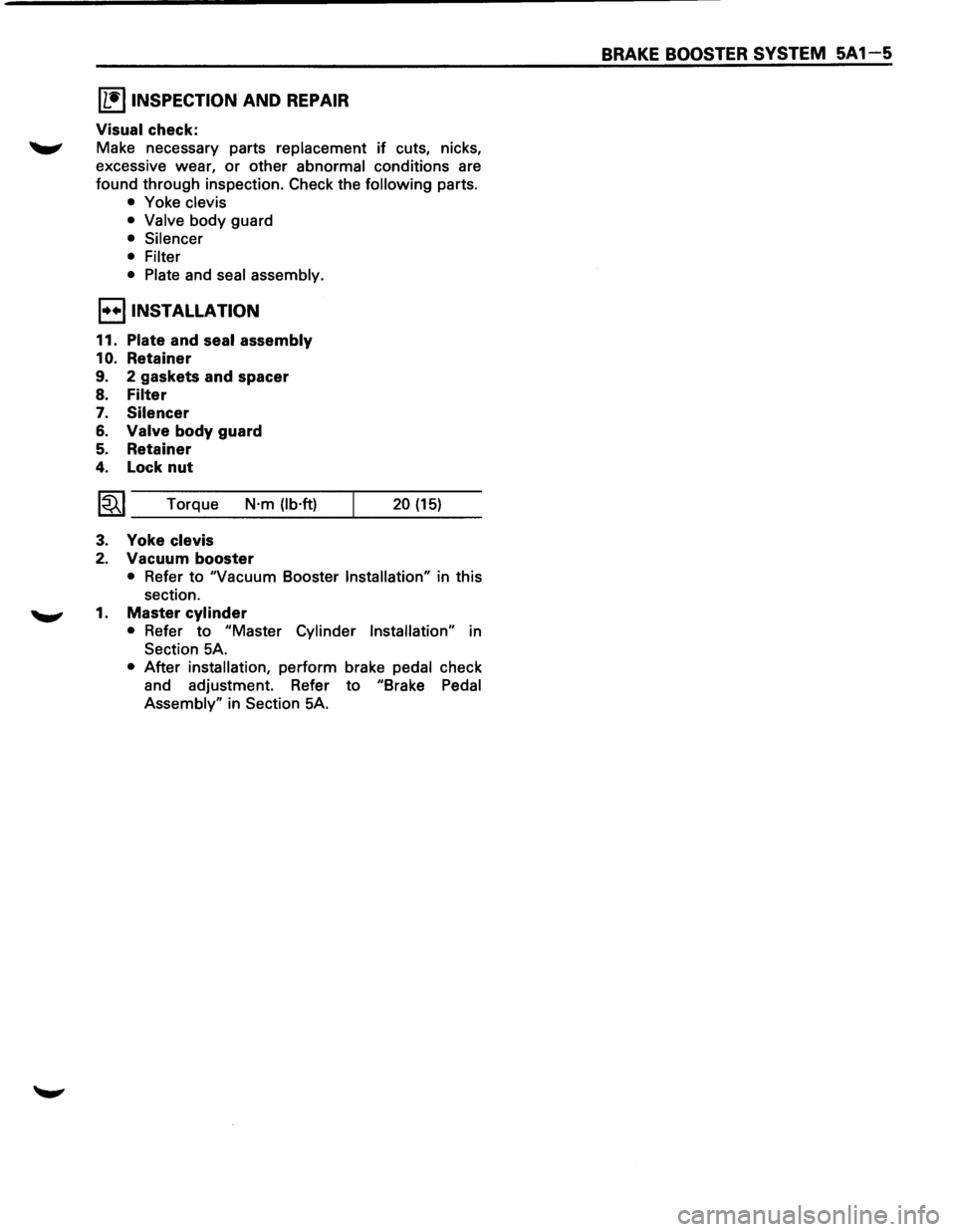
[1!) INSPECTION AND REPAIR
Visual check:
'-"' Make necessary parts replacement if cuts, nicks,
excessive wear,
or other abnormal conditions are
found through inspection.
Check the following parts.
• Yoke clevis
• Valve
body guard
• Silencer
• Filter
• Plate
and seal assembly.
I••IINSTALLATION
11. Plate and seal assembly
1 0. Retainer
9. 2 gaskets and spacer
8. Filter
7. Silencer
6. Valve body guard
5. Retainer
4. Lock nut
20 (15) 1~1 Torque N·m (lb·ft) ----------1....---
3. Yoke clevis
2. Vacuum booster
• Refer to "Vacuum Booster Installation" in this
section.
'-"" 1. Master cylinder
• Refer to "Master Cylinder Installation" in
Section 5A.
• After installation, perform brake pedal check
and adjustment. Refer
to "Brake Pedal
Assembly" in Section 5A.
BRAKE BOOSTER SYSTEM 5A 1-5
Page 499 of 1928
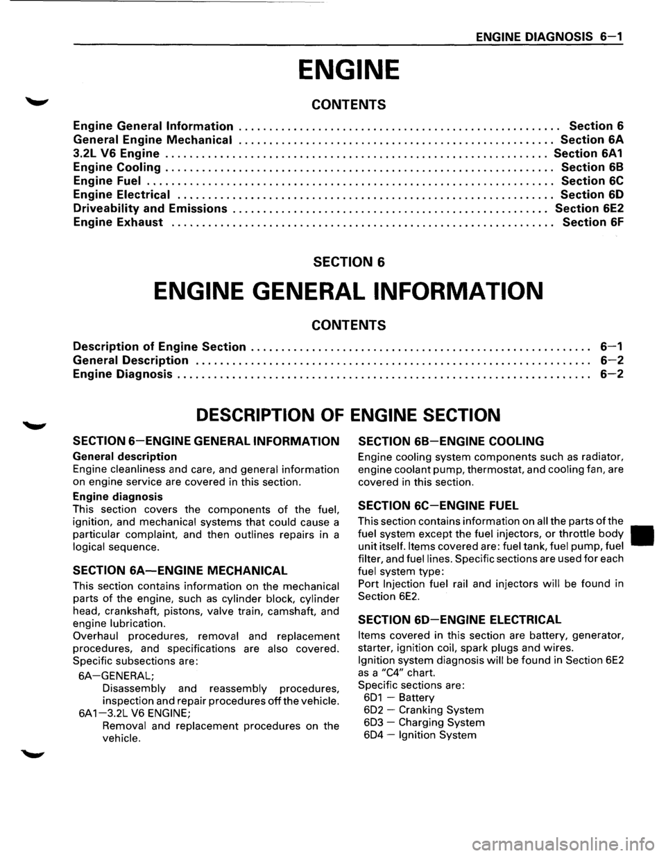
ENGINE DIAGNOSIS S-1
ENGINE
CONTENTS
Engine General Information . . . . . . . . . . . . . . . . . . . . . . . . . . . . . . . . . . . . . . . . . . . . . . . . . . . . . Section S
General
Engine Mechanical .................................................... Section SA
3.2L VS Engine ............................................................... Section SA1
Engine Cooling . . . . . . . . . . . . . . . . . . . . . . . . . . . . . . . . . . . . . . . . . . . . . . . . . . . . . . . . . . . . . . . . Section S8
Engine Fuel . . . . . . . . . . . . . . . . . . . . . . . . . . . . . . . . . . . . . . . . . . . . . . . . . . . . . . . . . . . . . . . . . . . Section SC
Engine Electrical . . . . . . . . . . . . . . . . . . . . . . . . . . . . . . . . . . . . . . . . . . . . . . . . . . . . . . . . . . . . . . Section SD
Driveability and Emissions . . . . . . . . . . . . . . . . . . . . . . . . . . . . . . . . . . . . . . . . . . . . . . . . . . . . Section SE2
Engine Exhaust . . . . . . . . . . . . . . . . . . . . . . . . . . . . . . . . . . . . . . . . . . . . . . . . . . . . . . . . . . . . . . . Section SF
SECTION 6
ENGINE GENERAL INFORMATION
CONTENTS
Description of Engine Section . . . . . . . . . . . . . . . . . . . . . . . . . . . . . . . . . . . . . . . . . . . . . . . . . . . . . . . . S-1
General Description . . . . . . . . . . . . . . . . . . . . . . . . . . . . . . . . . . . . . . . . . . . . . . . . . . . . . . . . . . . . . . . . . S-2
Engine Diagnosis . . . . . . . . . . . . . . . . . . . . . . . . . . . . . . . . . . . . . . . . . . . . . . . . . . . . . . . . . . . . . . . . . . . . S-2
DESCRIPTION OF ENGINE SECTION
SECTIONS-ENGINE GENERAL INFORMATION SECTION S8-ENGINE COOLING
General description
Engine cleanliness and care, and general information
on engine service are covered in this section.
Engine diagnosis
This section covers the components of the fuel,
ignition, and mechanical systems that could cause a
particular complaint, and then outlines repairs in a
logical sequence.
SECTION SA-ENGINE MECHANICAL
This section contains information on the mechanical
parts of the engine, such as cylinder block, cylinder
head, crankshaft, pistons, valve train, camshaft, and
engine
lubrication.
Overhaul
procedures, removal and replacement
procedures, and specifications are also covered.
Specific subsections are:
SA-GENERAL;
Disassembly and reassembly procedures,
inspection and repair procedures
off the vehicle.
6A 1-3.2L V6 ENGINE;
Removal
and replacement procedures on the
vehicle.
Engine cooling system components such as radiator,
engine
coolant pump, thermostat, and cooling fan, are
covered
in this section.
SECTION SC-ENGINE FUEL
This section contains information on all the parts of the
fuel system except the fuel injectors, or throttle body II
unit itself. Items covered are: fuel tank, fuel pump, fuel
filter,
and fuel lines. Specific sections are used for each
fuel system type:
Port
Injection fuel rail and injectors will be found in
Section
6E2.
SECTION SD-ENGINE ELECTRICAL
Items covered in this section are battery, generator,
starter, ignition
coil, spark plugs and wires.
Ignition system diagnosis will be found in Section 6E2
as a "C4" chart.
Specific sections are:
601 -Battery
602 - Cranking System
603 -Charging System
604 -Ignition System
Page 503 of 1928
ENGINE DIAGNOSIS 6-5
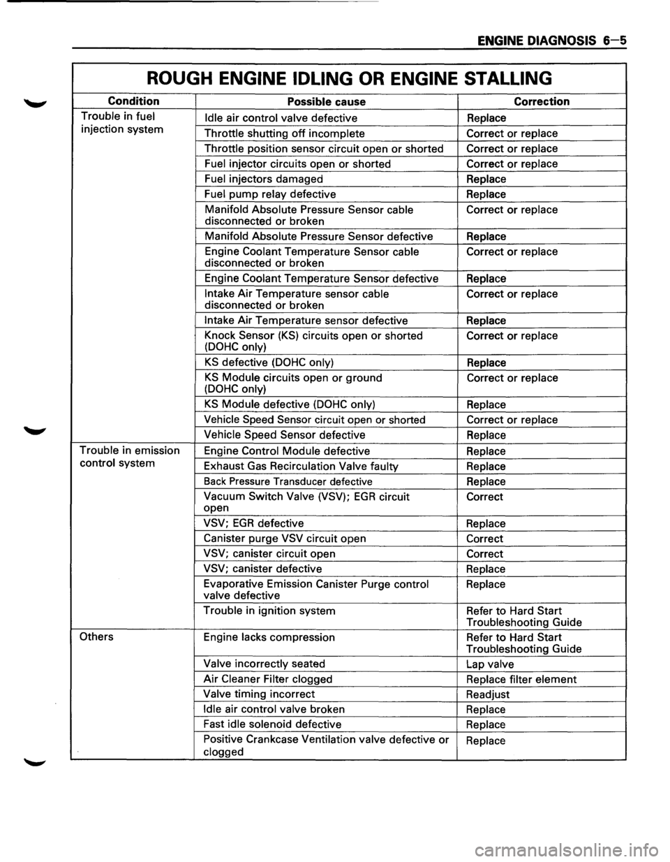
ROUGH ENGINE IDLING OR ENGINE STALLING
Condition Possible cause Correction
Trouble in fuel
Idle air control valve defective Replace
injection system
Throttle shutting
off incomplete Correct or replace
Throttle position sensor circuit open
or shorted Correct or replace
Fuel injector circuits open or shorted Correct or replace
Fuel injectors damaged
Replace
Fuel pump relay defective Replace
Manifold Absolute Pressure Sensor
cable Correct or replace
disconnected
or broken
Manifold Absolute Pressure Sensor defective
Replace
Engine Coolant Temperature Sensor cable Correct
or replace
disconnected
or broken
Engine Coolant Temperature Sensor defective
Replace
Intake Air Temperature sensor cable Correct or replace
disconnected
or broken
Intake Air Temperature sensor defective
Replace
Knock Sensor
(KS) circuits open or shorted
Correct or replace
(DOHC only)
KS defective (DOHC only) Replace
KS Module circuits open or ground
Correct or replace
(DOHC only)
KS Module defective (DOHC only) Replace
Vehicle Speed Sensor circuit open or shorted
Correct or replace
Vehicle Speed Sensor defective
Replace
Trouble in emission
Engine Control Module defective
Replace
control system
Exhaust Gas Recirculation
Valve faulty
Replace
Back Pressure Transducer defective
Replace
Vacuum Switch Valve (VSV); EGR circuit
Correct
open
VSV; EGR defective Replace
Canister purge
VSV circuit open
Correct
VSV; canister circuit open
Correct
VSV; canister defective
Replace
Evaporative Emission Canister Purge control
Replace
valve defective
Trouble in ignition system
Refer
to Hard Start
Troubleshooting Guide
Others Engine lacks compression
Refer to Hard Start
Troubleshooting Guide
Valve incorrectly seated
Lap valve
Air Cleaner Filter clogged
Replace filter element
Valve timing incorrect
Readjust
Idle air control valve broken
Replace
Fast
idle solenoid defective
Replace
Positive Crankcase Ventilation valve defective
or Replace
clogged
Page 505 of 1928
ENGINE DIAGNOSIS 6-7
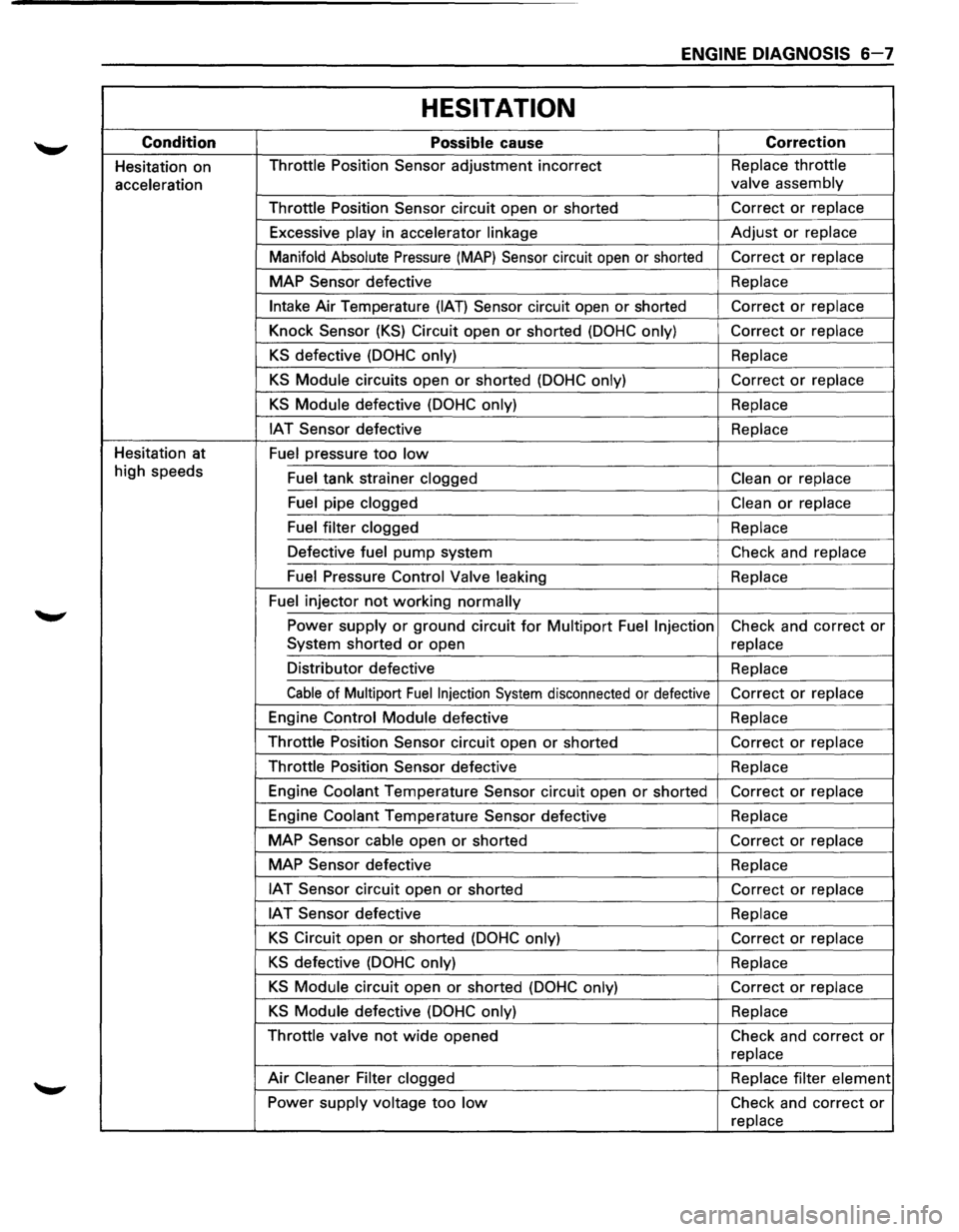
HESITATION
Condition Possible cause Correction
Hesitation on Throttle
Position Sensor adjustment incorrect Replace
throttle
acceleration valve
assembly
Throttle Position Sensor circuit open
or shorted Correct
or replace
Excessive play in accelerator linkage
Adjust or replace
Manifold Absolute
Pressure (MAP) Sensor circuit open or shorted Correct or replace
MAP Sensor defective Replace
Intake Air
Temperature (IAT) Sensor circuit open or shorted Correct or replace
Knock Sensor
(KS) Circuit open or shorted (DOHC only) Correct or replace
KS defective (DOHC only) Replace
KS Module circuits open or shorted (DOHC only) Correct or replace
KS Module defective (DOHC only) Replace
IAT Sensor defective Replace
Hesitation at
Fuel pressure
too low
high speeds
Fuel tank strainer clogged Clean or replace
Fuel pipe clogged
Clean or replace
Fuel filter clogged
Replace
Defective fuel
pump system Check and replace
Fuel Pressure Control Valve leaking Replace
Fuel injector
not working normally
Power supply or ground circuit for Multipart Fuel Injection Check and correct or
System shorted or open
replace
Distributor defective Replace
Cable of Multipart Fuel Injection System disconnected or defective Correct or replace
Engine Control Module defective Replace
Throttle Position Sensor circuit open
or shorted Correct or replace
Throttle Position Sensor defective Replace
Engine Coolant Temperature Sensor circuit open
or shorted Correct or replace
Engine Coolant Temperature Sensor defective Replace
MAP Sensor cable open
or shorted Correct or replace
MAP Sensor defective
Replace
IAT Sensor circuit open or shorted
Correct or replace
IAT Sensor defective Replace
KS Circuit open or shorted (DOHC only)
Correct or replace
KS defective (DOHC only) Replace
KS Module circuit open or shorted (DOHC only) Correct or replace
KS Module defective (DOHC only) Replace
Throttle valve
not wide opened
Check and correct or
replace
Air Cleaner Filter clogged
Replace filter element
Power supply voltage
too low Check and correct or
replace