radiator ISUZU TROOPER 1995 Repair Manual
[x] Cancel search | Manufacturer: ISUZU, Model Year: 1995, Model line: TROOPER, Model: ISUZU TROOPER 1995Pages: 1928
Page 1036 of 1928
7A-164 AUTOMATIC TRANSMISSION (4L30-E)
20. Third crossmember
~~~ Torque N·m(lb.ft) 50 (37)
19. Rear mount nut
~~~ Torque N·mOb·ft) 41 (30)
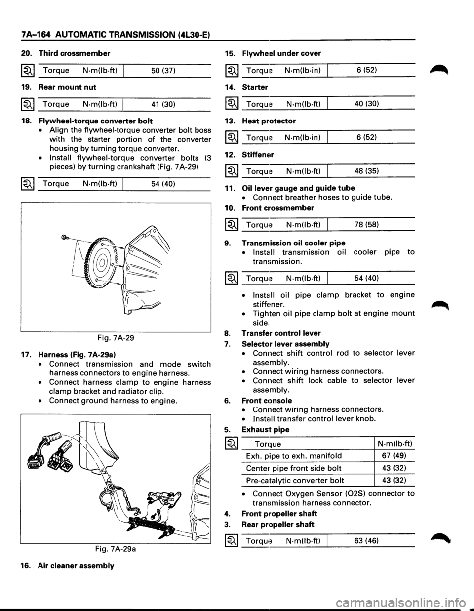
18. Flywheel-torque converter bolt
• Align
the flywheel-torque converter bolt boss
with the starter portion of the converter
housing
by turning torque converter.
• Install flywheel-torque converter bolts (3
pieces) by turning crankshaft (Fig. 7 A-29)
~~~ Torque N·mOb·ft) 54 (40)
Fig. 7A-29
17. Harness (fig. 7A-29a)
• Connect transmission and mode switch
harness connectors to engine harness.
• Connect harness clamp to engine harness
clamp bracket and radiator clip.
•
Connect ground harness to engine.
Fig. 7A-29a
16. Air
cleaner assembly
15. Flywheel under cover
~~~ TorqUte N·mOb·in)
14. Starter
~~~ Torqu,e N·m(lb·ft)
13. Heat protector
~~~ Torqu'e N·m(lb·in)
12. Stiffener
N·m(lb·ft)
11. Oil lever gauge and guide tube 6
(52)
40 (30)
6 (52)
48 (35)
• Connect breather hoses to guide tube.
10. Front crossmember
~~~ Torque N·m(lb·ft) I 78 (58)
9. Transmission oil cooler pipe
• Install transmission oil cooler pipe to
transmission.
~~~ Torqwe N·m(lb·ft) I 54 (40)
•
lnsta1ll oil pipe clamp bracket to engine
stiffener. .~
• Tighten oil pipe clamp bolt at engine mount
side.
8. Transfer control lever
7. Selector lever assembly
•
Connect shift control rod to selector lever
assembly.
•
Connect wiring harness connectors.
• Connect shift lock cable to selector lever
assembly.
6. Front cc>nsole
• Connect wiring harness connectors.
• Install transfer control lever knob.
5. Exhaust pipe
I~I ___ T_o_r_q~_ue __________________ 4-N_·_m_(l_b_·ft __ )
Exh. pipe
to exh. manifold 67 (49)
Center pipe
front side bolt 43 (32)
Pre-catalytic converter bolt 43 (32)
• Connect Oxygen Sensor (025) connector to
transmission harness connector.
4. Front propeller shaft
3. Rear propeller shaft
~~~ Torqwe N·mOb·ft) 63 (46)
Page 1262 of 1928
8 -72 CHASSIS ELECTRICAL
HEADLIGHT
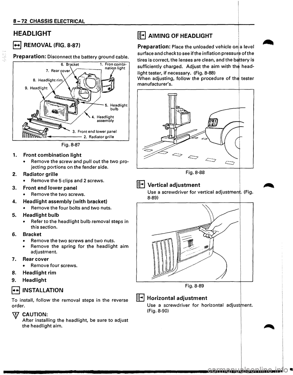
E) REMOVAL (FIG. 8-87)
Preparation: Disconnect the battery ground cable.
Fig. 8-87
1. Front combination light
• Remove the screw and pull out the two pro
jecting
portions on the fender side.
2. Radiator grille
• Remove the 5 clips and 2 screws.
3. Front end lower panel
• Remove the two screws.
4. Headlight assembly (with bracket)
• Remove the four bolts and two nuts.
5. Headlight bulb
• Refer to the headlight bulb removal steps in
this section.
6. Bracket
• Remove the two screws and two nuts.
• Remove the spring for the headlight aim
adjustment.
7. Rear cover
• Remove four screws.
8. Headlight rim
9. Headlight
E3 INSTALLATION
To install, follow the removal steps in the reverse
order.
W CAUTION:
After installing the headlight, be sure to adjust
the headlight aim.
(E AIMING OF HEADLIGHT
Preparation: Place the unloaded vehicle on a level
surface and check to see ifthe inflation pressur oft he
tires is correct, the lenses are clean, and the b ttery is
sufficiently charged.
Adjust the aim with th head
light tester, if necessary. (fig. 8-88)
When adjusting,
follow the procedure of th tester
manufacturer's.
Fig. 8-88
1~1 .... 1 Vertical adjustment
Use a screwdriver for vertical adjustmen . (Fig.
8-89)
Fig. 8-89
m .... l Horizontal adjustment
Use a screwdriver for horizontal adjust ent.
(Fig.
8-90)
..
Page 1314 of 1928
8-124 CHASSIS ELECTRICAL
1. Backup light switch For low note (Fig.S-151)
• Remove the connectors.
• Remove the switch by turning it counter
clockwise.
B INSTALLATION
To install, follow the removal steps in the reverse
order,
noting the following point.
1.
Backup light switch
li:i1 • Apply liquid gasket to the screw portion of
~ the switch to prevent oil leak.
BACKUP LIGHT BULB
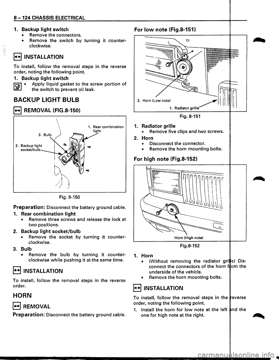
B REMOVAL (FIG.S-150)
2. Backup light
socket/bulb
i ''V
f
~h /) i/
Fig. 8-150
Preparation: Disconnect the battery ground cable.
1. Rear combination light
• Remove three screws and release the lock at
two positions.
2.
Backup light socket/bulb
• Remove the socket by turning it counter
clockwise.
3. Bulb
• Remove the bulb by turning it counter
clockwise
while pushing it at the same time.
B INSTALLATION
To install, follow the removal steps in the reverse
order.
HORN
B REMOVAL
Preparation: Disconnect the battery ground cable.
Fig. 8-151
1.
Radiator grille
o Remove five clips and two screws.
2. Horn
o Disconnect the connector.
• Remove the horn mounting bolts.
For high note (Fig.S-152)
Horn (High note)
Fig.8-152
1. Horn
• {Without removing the radiator gri e) Dis
connect the connectors of the horn f om the
underside
of the vehicle.
•
Remove the horn mounting bolts.
8 INSTALLATION
To install, follow the removal steps in the everse
order, noting the
following point.
1. Install the horn for low note at the left nd the
one
for high note at the right. ~
Page 1742 of 1928
9J-118 Supplemental Restraint System
attachments
- Driver seat and belt
- Passenger seat and belt
- Dual Pole Arming
Sensor
-Discriminating Sensors
-DERM
The sensor replacement policy specifies mandatory
replacement of the sensors, after crash involving
AIR
BAG deployment. If AIR BAG has not been deployd,
Replace the sensors
in the area of accident damage only.
The
"area of accident damage" is defined as that area of
the vehicle which is crushed, bent ,or damaged in other
ways. An example might be a front-end collision
in which
the forward portions of the vehicle have contacted
another vehicle, tree, guardrail,etc.
In this example,
1)
If AIR BAG has deployed, All Sensor should be
replaced.
2)
If AIR BAG has not deployed, replace the sensors
in the area of accident damage only.
sensor(s) on the radiator tie bar would require
replacement, since that portion of the vehicle was
damaged in the accident. The Dual Pole Arming Sensor
would not require mandatory replacement. Of course, if
the DERM sets a code and the diagnostic chart leads to
a faulty sensor that was not in the area of accident
damage, that sensor should also be replaced.Sensors
in
the area of accident damage should be replaced even if
those sensors do not appear to be damaged. Do not
attempt to determine whether a sensor is
OK-ALWAYS
replace it if it is in the area of accident damage.Aiso, if a
sensor is
in an area of accident damage,but the SRS has
NOT been deployed,replace the sensor.The sensor
bracket may be slightly bent,wiring may be
damaged, etc., and the sensor might not work properly
in
another collision. Again, do not attempt to determine
whether a sensor is
OK --ALWAYS replace it if it is in
the area of accident damage. Also,
inspect
SRS coil assembly wiring and steering
wheel for any signs of scorching, melting, or damage due
to excessive heat.
If the coil assembly wire or steering ~
wheel is damaged, replace them. The steering column
and wheel must be dimensionally checked to determine
if they are damaged. Refer to
in this Section 3 of this
manual.
Never use
SRS parts from another vehicle. This does not
include remanufactured parts purchased from an
authorized
ISUZU Dealer; they may be used for SRS
repairs.
Do not attempt to repair the forward discriminating
sensors ,the dual pole arming senor, the DERM, the
SRS
coil assembly, the inflator modules, the steering wheel, or
the steering column. Service of these items is
replacement only.
Verify replacement part numbers.
CAUTION: PROPER OPERATION OF THE
SENSORS AND SUPPLEMENTAL RESTRAINT
SYSTEM(SRS)REQUIRES THAT ANY REPAIRS TO
THE VEHICLE STRUCTURE RETURN IT TO ITS
ORIGINAL PRODUCTION CONFIGURATION.
II