radiator ISUZU TROOPER 1995 User Guide
[x] Cancel search | Manufacturer: ISUZU, Model Year: 1995, Model line: TROOPER, Model: ISUZU TROOPER 1995Pages: 1928
Page 113 of 1928
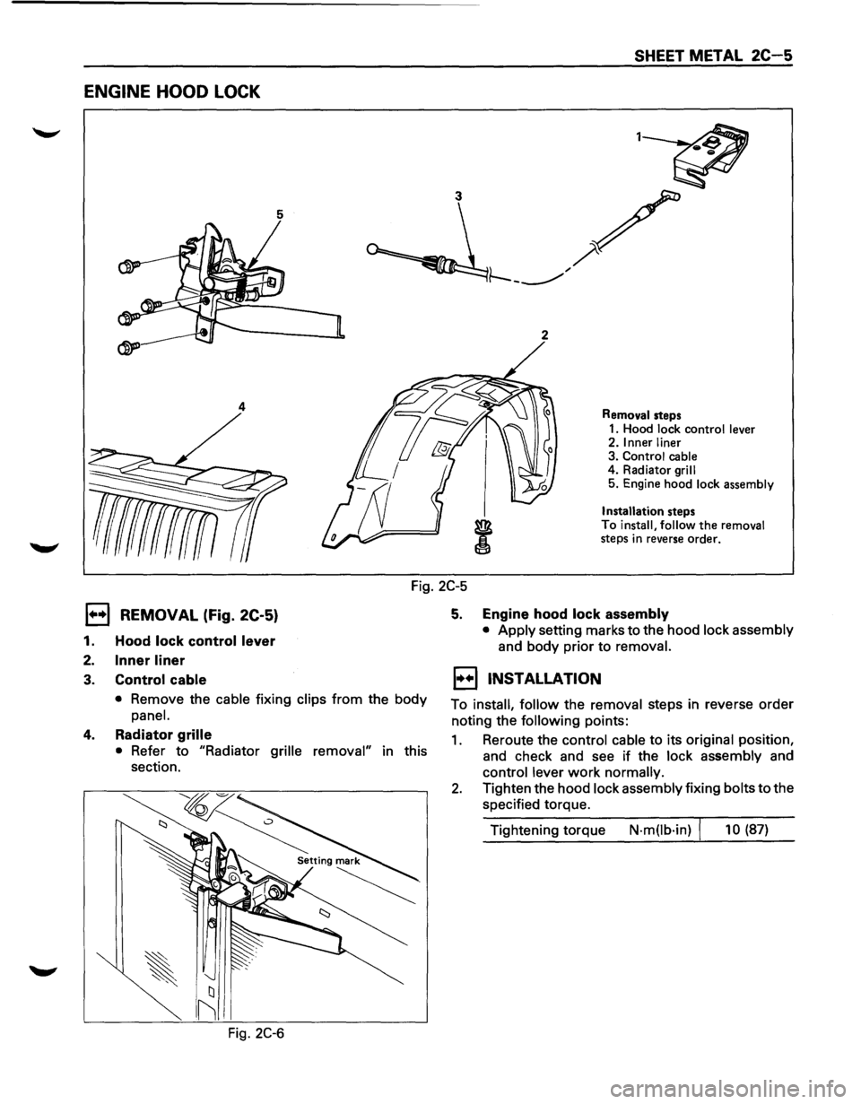
ENGINE HOOD LOCK
5
2
4
SHEET METAL 2C-5
Removal steps
1. Hood lock control lever
2. Inner liner
3. Control cable
4. Radiator
grill
5. Engine hood lock assembly
Installation steps
To install, follow the removal
steps in reverse order.
Fig. 2C-5
1••1 REMOVAL (Fig. 2C-5)
1. Hood lock control lever
2. Inner liner
3. Control cable
• Remove the cable fixing clips from the body
panel.
4. Radiator grille
• Refer to "Radiator grille removal" in this
section.
Fig.
2C-6
5. Engine hood lock assembly
• Apply setting marks to the hood lock assembly
and body prior to removal.
EJ INSTALLATION
To install, follow the removal steps in reverse order
noting the
following points:
1. Reroute the control cable to its original position,
and check and see if the
lock assembly and
control lever work normally.
2. Tighten the hood lock assembly fixing bolts to the
specified torque.
Tightening torque
N·m(lb·in) I 10 (87)
Page 114 of 1928
2C-6 SHEET METAL
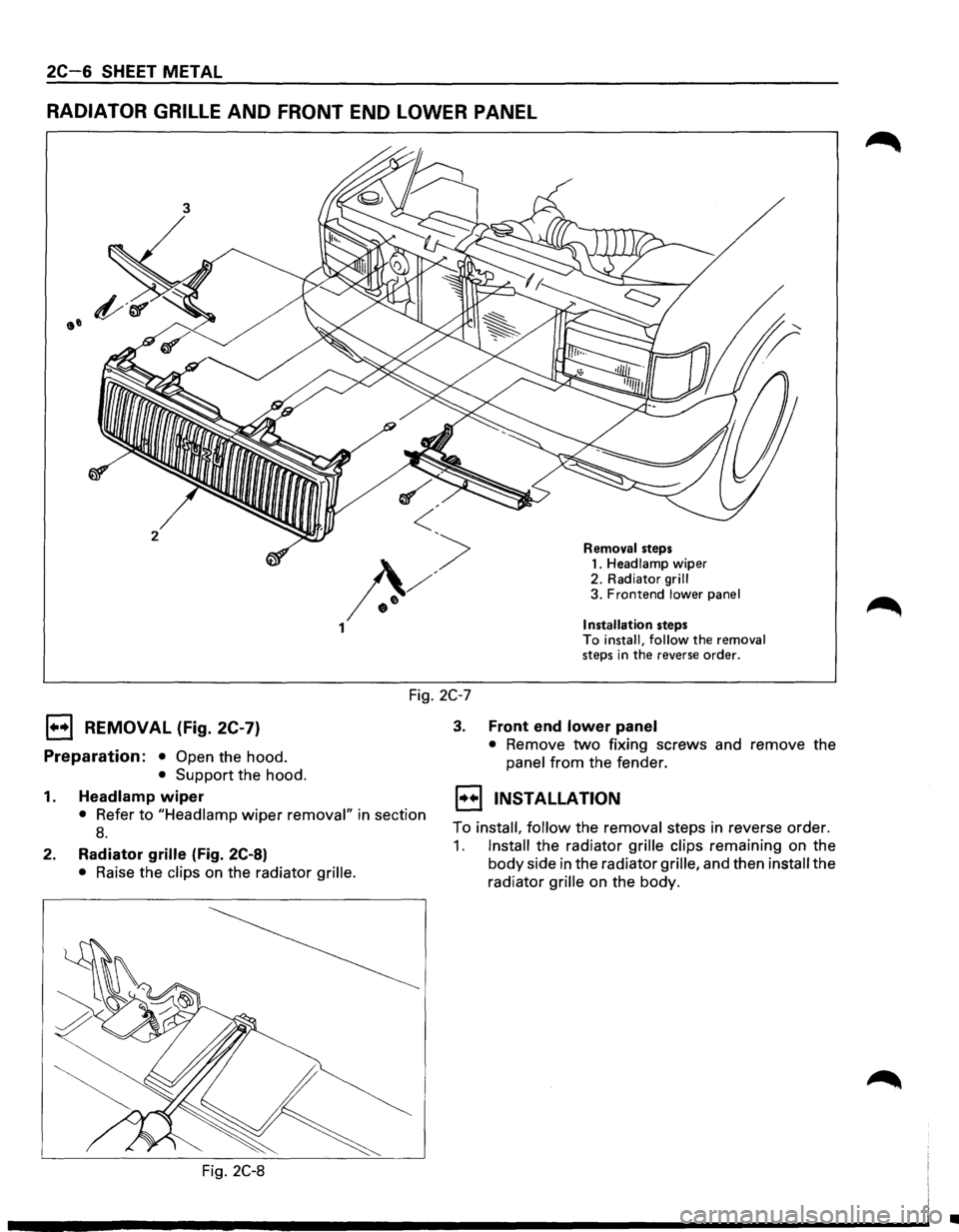
RADIATOR GRILLE AND FRONT END LOWER PANEL
3
2 Removal steps 1. Headlamp wiper
2. Radiator
grill 3. Frontend lower panel
Installation steps To install, follow the removal steps in the reverse order.
Fig. 2C-7
1••1 REMOVAL (Fig. 2C-7)
Preparation: • Open the hood.
• Support the hood.
1.
Headlamp wiper
• Refer to "Headlamp wiper removal" in section
8.
2. Radiator grille (Fig. 2C-8)
• Raise the clips on the radiator grille.
Fig. 2C-8
3. Front end lower panel
•
Remove two fixing screws and remove the
panel from the fender.
1••1 INSTALLATION
To install, follow the removal steps in reverse order.
1. Install the radiator grille clips remaining on the
body side in the radiator
grille, and then install the
radiator
grille on the body.
•
Page 339 of 1928
HYDRAULIC BRAKES SA-19
UNIT REPAIR
MASTER CYLINDER
• The master cylinder is not repairable and must
be replaced as complete assembly if found
defective.
INSPECTION
Excessive brake pedal travel, malfunction or dragging
brake suggests
that the master cylinder is defective. In
such cases perform the following visual check.
IL•I Visual check
Make parts replacement as required if wear, distortion,
nicks, cuts, corrosion,
or other abnormal conditions
are
found through the following parts inspection;
• Master cylinder body
• Fluid reservoir
• 0-ring
rfil FUNCTIONAL INSPECTION OF MASTER
l..!aJ CYLINDER PISTON (Fig. SA-20)
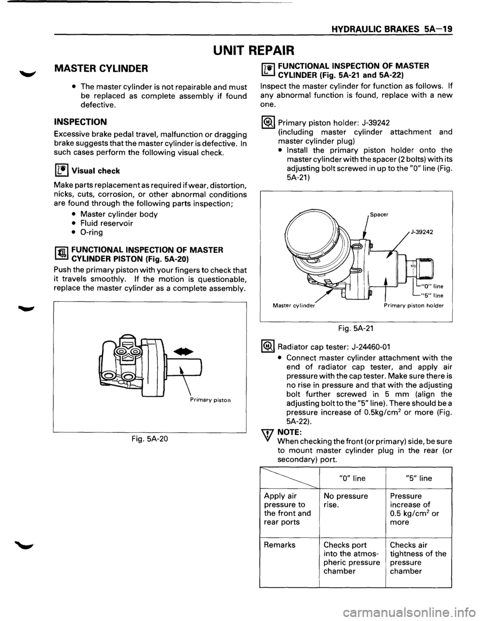
Push the primary piston with your fingers to check that
it travels smoothly. If the motion is questionable,
replace
the master cylinder as a complete assembly.
Primary piston
Fig. 5A-20
["j"1i"l FUNCTIONAL INSPECTION OF MASTER
I..!:::..J CYLINDER (Fig. 5A-21 and 5A-22)
Inspect the master cylinder for function as follows. If
any abnormal function is found, replace with a new
one.
1®.1 Primary piston holder: J-39242
(including master cylinder attachment and
master
cylinder plug)
• Install
the primary piston holder onto the
master
cylinder with the spacer (2 bolts) with its
adjusting
bolt screwed in up to the "0" line (Fig.
5A-21)
Master cylinder Primary piston holder
Fig. 5A-21
1®.1 Radiator cap tester: J-24460-01
•
Connect master cylinder attachment with the
end
of radiator cap tester, and apply air
pressure
with the cap tester. Make sure there is
no rise in pressure and
that with the adjusting
bolt further screwed in 5 mm (align the
adjusting
bolt to the "5" line). There should be a
pressure increase
of 0.5kg/cm2 or more (Fig.
5A-22).
\f7 NOTE:
VI When checking the front (or primary) side, be sure
to mount master cylinder plug in the rear (or
secondary) port.
~ "0" line "5" line
Apply air
No pressure Pressure
pressure
to rise. increase of
the front and 0.5 kg/cm2 or
rear ports more
Remarks Checks port Checks air
into the atmos-
tightness
of the
pheric pressure pressure
chamber chamber
Page 342 of 1928
SA-22 HYDRAULIC BRAKES
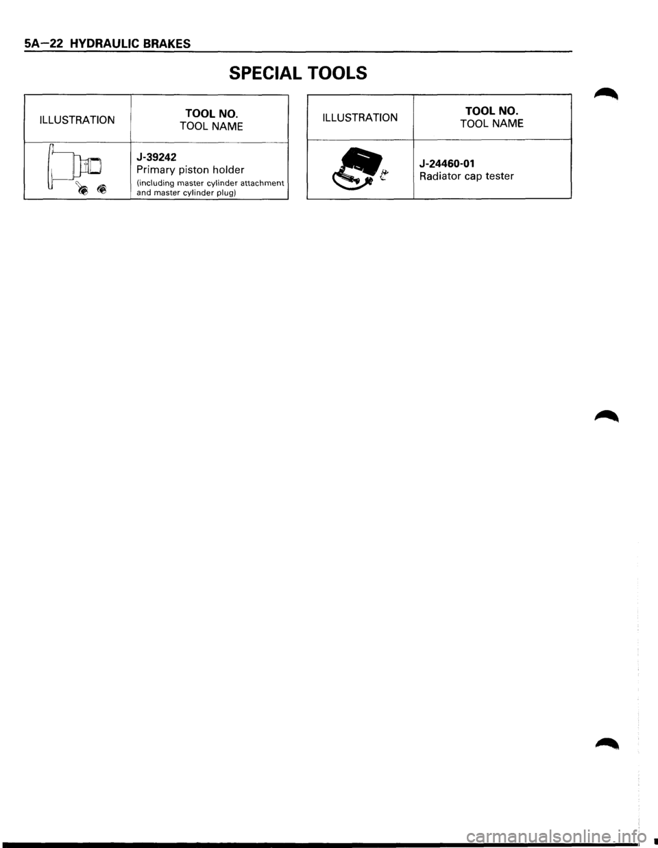
SPECIAL TOOLS
ILLUSTRATION TOOL
NO.
TOOL NAME ILLUSTRATION TOOL
NO.
TOOL NAME
~
J-39242
Primary piston holder
(including master cylinder attachment ~(i and master cylinder plug) ~t
J-24460-01
Radiator cap tester
•
Page 499 of 1928
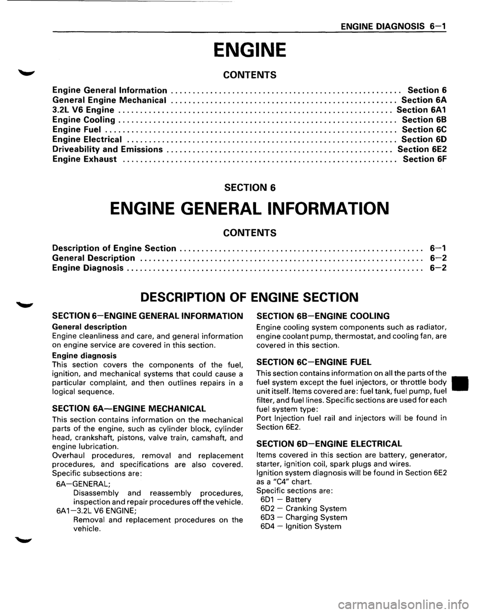
ENGINE DIAGNOSIS S-1
ENGINE
CONTENTS
Engine General Information . . . . . . . . . . . . . . . . . . . . . . . . . . . . . . . . . . . . . . . . . . . . . . . . . . . . . Section S
General
Engine Mechanical .................................................... Section SA
3.2L VS Engine ............................................................... Section SA1
Engine Cooling . . . . . . . . . . . . . . . . . . . . . . . . . . . . . . . . . . . . . . . . . . . . . . . . . . . . . . . . . . . . . . . . Section S8
Engine Fuel . . . . . . . . . . . . . . . . . . . . . . . . . . . . . . . . . . . . . . . . . . . . . . . . . . . . . . . . . . . . . . . . . . . Section SC
Engine Electrical . . . . . . . . . . . . . . . . . . . . . . . . . . . . . . . . . . . . . . . . . . . . . . . . . . . . . . . . . . . . . . Section SD
Driveability and Emissions . . . . . . . . . . . . . . . . . . . . . . . . . . . . . . . . . . . . . . . . . . . . . . . . . . . . Section SE2
Engine Exhaust . . . . . . . . . . . . . . . . . . . . . . . . . . . . . . . . . . . . . . . . . . . . . . . . . . . . . . . . . . . . . . . Section SF
SECTION 6
ENGINE GENERAL INFORMATION
CONTENTS
Description of Engine Section . . . . . . . . . . . . . . . . . . . . . . . . . . . . . . . . . . . . . . . . . . . . . . . . . . . . . . . . S-1
General Description . . . . . . . . . . . . . . . . . . . . . . . . . . . . . . . . . . . . . . . . . . . . . . . . . . . . . . . . . . . . . . . . . S-2
Engine Diagnosis . . . . . . . . . . . . . . . . . . . . . . . . . . . . . . . . . . . . . . . . . . . . . . . . . . . . . . . . . . . . . . . . . . . . S-2
DESCRIPTION OF ENGINE SECTION
SECTIONS-ENGINE GENERAL INFORMATION SECTION S8-ENGINE COOLING
General description
Engine cleanliness and care, and general information
on engine service are covered in this section.
Engine diagnosis
This section covers the components of the fuel,
ignition, and mechanical systems that could cause a
particular complaint, and then outlines repairs in a
logical sequence.
SECTION SA-ENGINE MECHANICAL
This section contains information on the mechanical
parts of the engine, such as cylinder block, cylinder
head, crankshaft, pistons, valve train, camshaft, and
engine
lubrication.
Overhaul
procedures, removal and replacement
procedures, and specifications are also covered.
Specific subsections are:
SA-GENERAL;
Disassembly and reassembly procedures,
inspection and repair procedures
off the vehicle.
6A 1-3.2L V6 ENGINE;
Removal
and replacement procedures on the
vehicle.
Engine cooling system components such as radiator,
engine
coolant pump, thermostat, and cooling fan, are
covered
in this section.
SECTION SC-ENGINE FUEL
This section contains information on all the parts of the
fuel system except the fuel injectors, or throttle body II
unit itself. Items covered are: fuel tank, fuel pump, fuel
filter,
and fuel lines. Specific sections are used for each
fuel system type:
Port
Injection fuel rail and injectors will be found in
Section
6E2.
SECTION SD-ENGINE ELECTRICAL
Items covered in this section are battery, generator,
starter, ignition
coil, spark plugs and wires.
Ignition system diagnosis will be found in Section 6E2
as a "C4" chart.
Specific sections are:
601 -Battery
602 - Cranking System
603 -Charging System
604 -Ignition System
Page 507 of 1928
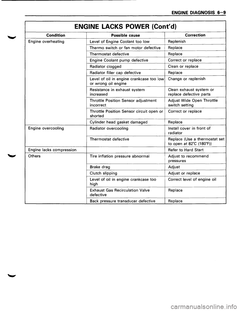
ENGINE DIAGNOSIS 6-9
ENGINE LACKS POWER (Cont'd)
Condition Possible cause Correction
Engine overheating
Level of Engine Coolant too low Replenish
Thermo switch or fan motor defective Replace
Thermostat defective Replace
Engine
Coolant pump defective Correct or replace
Radiator clogged
Clean or replace
Radiator
filler cap defective Replace
Level
of oil in engine crankcase too low Change or replenish
or
wrong oil engine
Resistance in exhaust system
Clean exhaust system or
increased replace
defective parts
Throttle Position Sensor adjustment Adjust
Wide Open Throttle
incorrect switch setting
Throttle Position Sensor circuit open
or Correct or replace
shorted
Cylinder head gasket damaged Replace
Engine overcooling
Radiator
overcooling Install cover
in front of
radiator
Thermostat defective Replace
(Use a thermostat set
to open at a2·c (180.F))
Engine
lacks compression Refer to Hard Start
Others Tire inflation pressure
abnormal Adjust to recommend
pressures
Brake drag Adjust
Clutch slipping Adjust or replace
Level
of oil in engine crankcase too Correct level of engine oil
high
Exhaust Gas
Recirculation Valve Replace
defective
Back pressure transducer defective
Replace
Page 578 of 1928
·,'
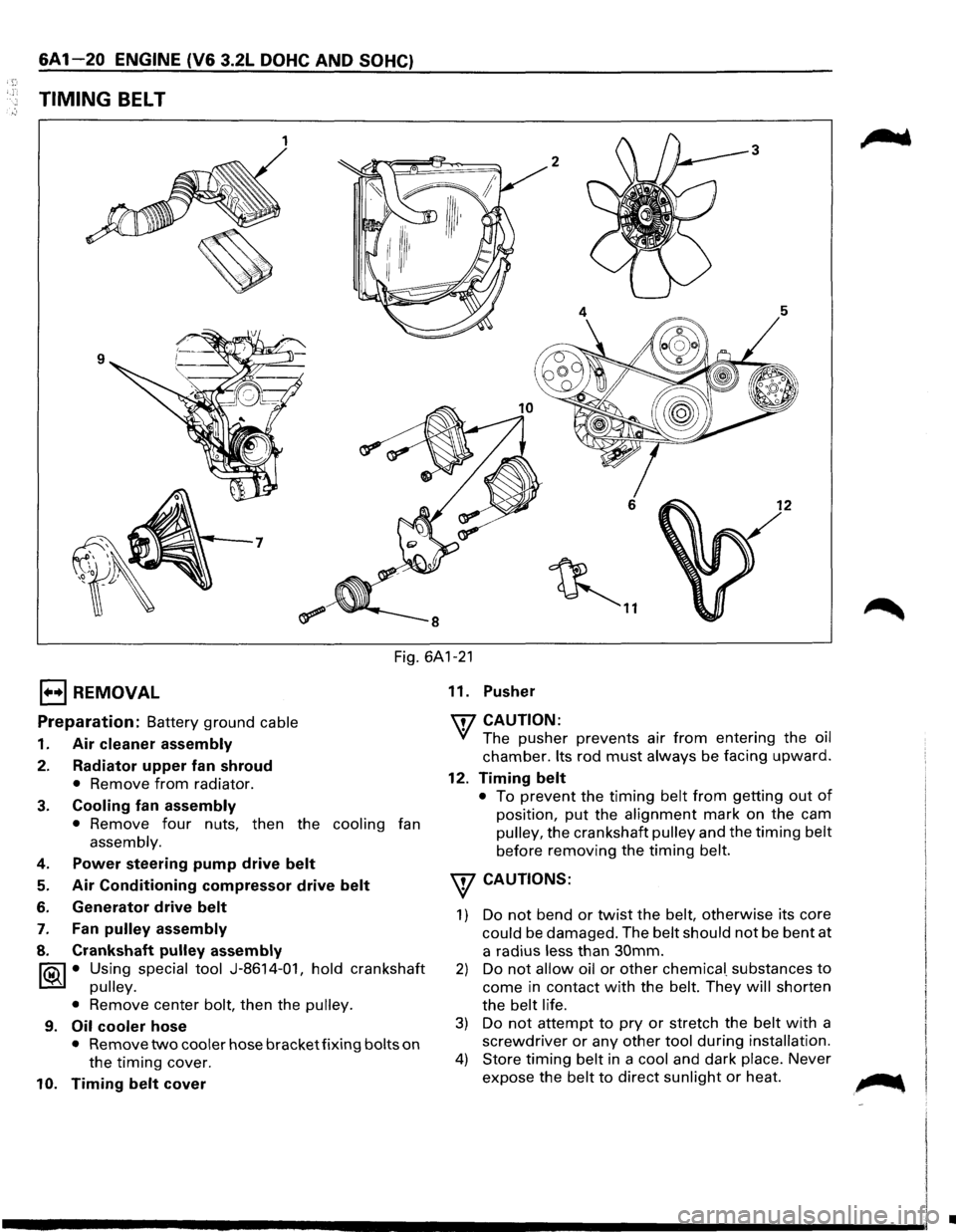
6A1-20 ENGINE (V6 3.2L DOHC AND SOHC)
TIMING BELT
1 3
2
6 12
~ ..
Fig. 6A1-21
1••1 REMOVAL
Preparation: Battery ground cable
1. Air cleaner assembly
2. Radiator upper fan shroud
• Remove from radiator.
3. Cooling fan assembly
• Remove four nuts, then the cooling fan
assembly.
4. Power steering pump drive belt
5. Air Conditioning compressor drive belt
6. Generator drive belt
7. Fan pulley assembly
8. Crankshaft pulley assembly
~ • Using special tool J-8614-01, hold crankshaft
~ pulley.
•
Remove center bolt, then the pulley.
9. Oil cooler hose
• Remove two cooler hose bracket fixing bolts on
the timing cover.
10. Timing belt cover 11.
Pusher
'IT7 CAUTION:
'if The pusher prevents air from entering the oil
chamber. Its rod must always be facing upward.
12. Timing belt
• To prevent the timing belt from getting out of
position, put the alignment mark on the cam
pulley, the crankshaft pulley and the timing belt
before removing the timing belt.
w CAUTIONS:
1) Do not bend or twist the belt, otherwise its core
could be damaged. The belt should not be bent at
a radius
less than 30mm.
2) Do not allow oil or other chemica[ substances to
come in contact with the belt. They will shorten
the
belt life.
3) Do not attempt to pry or stretch the belt with a
screwdriver or any other tool during installation.
4) Store timing belt in a cool and dark place. Never
expose the
belt to direct sunlight or heat. ~
•
Page 581 of 1928
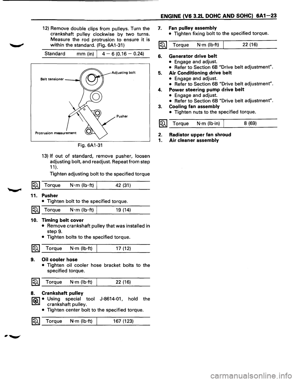
12) Remove double clips from pulleys. Turn the
crankshaft
pulley clockwise by two turns.
Measure the rod protrusion to ensure
it is
within the standard. (Fig. 6A 1-31)
Standard
mm (in) I 4 - 6 (0.16 -0.24)
Adjusting bolt
Pusher
Fig. 6A1-31
13) If out of standard, remove pusher, loosen
adjusting bolt, and readjust. Repeat from step
11 ).
Tighten adjusting bolt to the specified torque
1~1 Torque N·m (lb·ft) I 42 (31)
11. Pusher
• Tighten bolt to the specified torque.
1~1 Torque N·m (lb·ft) I 19 (14)
10. Timing belt cover
• Remove crankshaft pulley that was installed in
step
9.
• Tighten bolts to the specified torque.
~~~ Torque N·m (lb·ft) I 17 (12)
9. Oil cooler hose
• Tighten oil cooler hose bracket bolts to the
specified torque.
~~~ Torque N·m (lb·ft) I 22 (16)
8. Crankshaft pulley
l"iQ\1 • Using special tool J-8614-01, hold the
~ crankshaft pulley.
•
Tighten center bolt to the specified torque.
1~1 Torque N·m (lb·ft) 167 (123)
ENGINE (V6 3.2L DOHC AND SOHC) 6A1-23
7. Fan pulley assembly
• Tighten fixing bolt to the specified torque.
~~~ Torque N·m (lb·ft) 22 (16)
6. Generator drive belt
• Engage and adjust.
• Refer to Section 68 "Drive belt adjustment".
5. Air Conditioning drive belt
• Engage and adjust.
• Refer to Section 68 "Drive belt adjustment".
4. Power steering pump drive belt
• Engage and adjust.
• Refer to Section 68 "Drive belt adjustment".
3. Cooling fan assembly
• Tighten nuts to the specified torque.
~~~ Torque N·m (lb·in) I 8 (69)
2. Radiator upper fan shroud
1. Air cleaner assembly
Page 582 of 1928
, r;
6A 1-24 ENGINE (V6 3.2L DOHC AND SOHC)
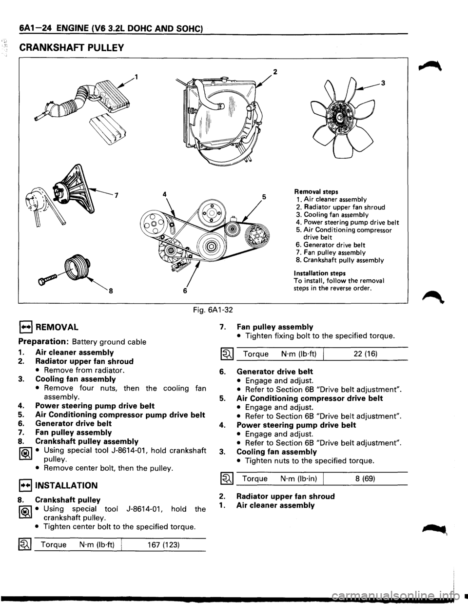
CRANKSHAFT PULLEY
1 2
7 4
6
3
Removal steps
1. Air
cleaner assembly
2. Radiator upper fan shroud
3. Cooling fan assembly
4. Power steering pump drive belt 5. Air Conditioning compressor
drive belt
6. Generator drive belt 7. Fan pulley assembly
8. Crankshaft pully assembly
Installation
steps To install, follow the removal steps in the reverse order.
Fig. 6A1-32
E) REMOVAL
Preparation: Battery ground cable
1. Air cleaner assembly
2. Radiator upper fan shroud
• Remove from radiator.
3. Cooling fan assembly
• Remove four nuts, then the cooling fan
assembly.
4. Power steering pump drive belt
5. Air Conditioning compressor pump drive belt
6. Generator drive belt
7. Fan pulley assembly
8. Crankshaft pulley assembly
IQil • Using special tool J-8614-01, hold crankshaft
I.:Sil pulley.
•
Remove center bolt, then the pulley.
I••IINSTALLATION
8. Crankshaft pulley
IQil • Using special tool J-8614-01, hold the
I.:Sil crankshaft pulley.
•
Tighten center bolt to the specified torque.
1~1 Torque N·m (lb·ft) 167 (123)
7. Fan pulley assembly
• Tighten fixing bolt to the specified torque.
1~1 Torque N·m (lb·ft) 22 (16)
6. Generator drive belt
• Engage and adjust.
• Refer to Section 68 "Drive belt adjustment".
5. Air Conditioning compressor drive belt
• Engage and adjust.
• Refer to Section 68 "Drive belt adjustment".
4. Power steering pump drive belt
• Engage and adjust.
• Refer to Section 68 "Drive belt adjustment".
3. Cooling fan assembly
• Tighten nuts to the specified torque.
~~~ Torque N·m (lb·in) I
2. Radiator upper fan shroud
1. Air cleaner assembly
8 (69)
•
Page 584 of 1928
6A1-26 ENGINE (V& 3.2L DOHC AND SOHC)
1••1 REMOVAL
Preparation: Battery ground cable
1. Air cleaner assembly
2. Radiator upper fan shroud
• Remove from radiator.
3. Cooling fan assembly
• Remove four nuts, then the cooling fan
assembly.
4. Accelerator Pedal cable
• Disconnect from throttle body and cable
bracket.
5. Vacuum booster hose
• Disconnect from common chamber.
6. Connectors
• Disconnect from Manifold Absolute Pressure,
canister Vacuum Switching Valve (VSV),
Exhaust
Gas Recirculation VSV, Intake Air
Temperature and ground cable.
7. High tension cables
• Disconnect from cylinder head cover.
8. Ignition Control Module assembly
• Disconnect three Electronic Ignition con
nectors.
• Remove three Electronic Ignition bracket fixing
bolts, and remove Electronic
Ignition assembly
with high tension cables.
9. Throttle body
• Remove four fixing bolts.
10. Vacuum hoses
• Disconnect vacuum hoses on canister VSV and
Exhaust Gas Recirculation
VSV from the
throttle body.
11. Positive Crankcase Ventilation hose
• Disconnect from common chamber.
12. Fuel Pressure Control Valve vacuum hose
• Disconnect from common chamber.
13. Evaporative Emission Canister Purge hose
• Disconnect from common chamber.
14. Exhaust Gas Recirculation Valve assembly
• Remove five bolts from common chamber,
exhaust manifold and cylinder head cover.
15. Common chamber
• Remove six bolts, two nuts and three bracket
fixing bolts, then remove the
common
chamber.
16. Fuelhoses
• Disconnect feed and return fuel hoses from fuel
pipes, and remove
two bracket fixing bolts on
the cylinder head cover.
17. Power steering pump drive belt
18. Air Conditioning compressor drive belt
19. Generator drive belt
20. Power steering pump
21. Fan pulley assembly
22. Crankshaft pulley assembly
lf5\l • Using special tool J-8614-01, hold crankshaft
t:::!il pulley.
•
Remove center bolt, then the pulley.
23. Oil cooler hose
• Remove two cooler hose bracket fixing bolts on
the timing belt cover.
24. Timing belt cover
25. Pusher
CAUTION:
The pusher prevents air from entering the oil chamber.
Its rod must always be facing upward.
26. Timing belt
CAUTIONS:
1) Do not bend or twist the belt, otherwise its core
could
be damaged. The belt should not be bent at
a radius less than 30mm.
2) Do not allow oil or other chemical substances to
come in contact with the belt. They will shorten
the belt life.
3) Do not attempt to pry or stretch the belt with a
screwdriver
or any other tool during installation.
4) Store timing belt in a cool and dark place. Never
expose the belt
to direct sunlight or heat.
27. Cylinder head cover
• Remove 11 fixing bolts, then the cylinder head
cover.
28. Camshaft
• Camshaft pulley fixing bolt and camshaft pulley
•
Front plate fixing bolts and front plate
• Camshaft bracket fixing bolts and camshaft
29. Rocker arm
• Fixing bolts and rocker arm
I••! INSTALLATION
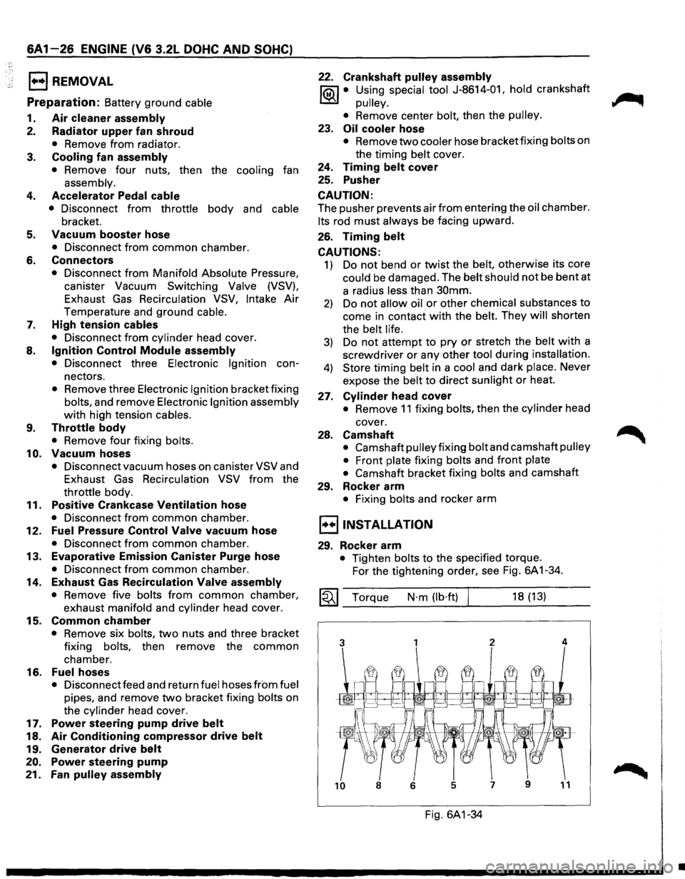
29. Rocker arm
• Tighten bolts to the specified torque.
For the tightening order, see Fig. 6A 1-34.
~~~ Torque N·m (lb·ft) 18 (13)
Fig. 6A1-34
•