radiator ISUZU TROOPER 1995 Service Manual
[x] Cancel search | Manufacturer: ISUZU, Model Year: 1995, Model line: TROOPER, Model: ISUZU TROOPER 1995Pages: 1928
Page 635 of 1928
B INSTALLATION
3. Thermostat
• Install thermostat into the thermostat hous
ing, making sure
that the jiggle valve in up
position.
2. Packing
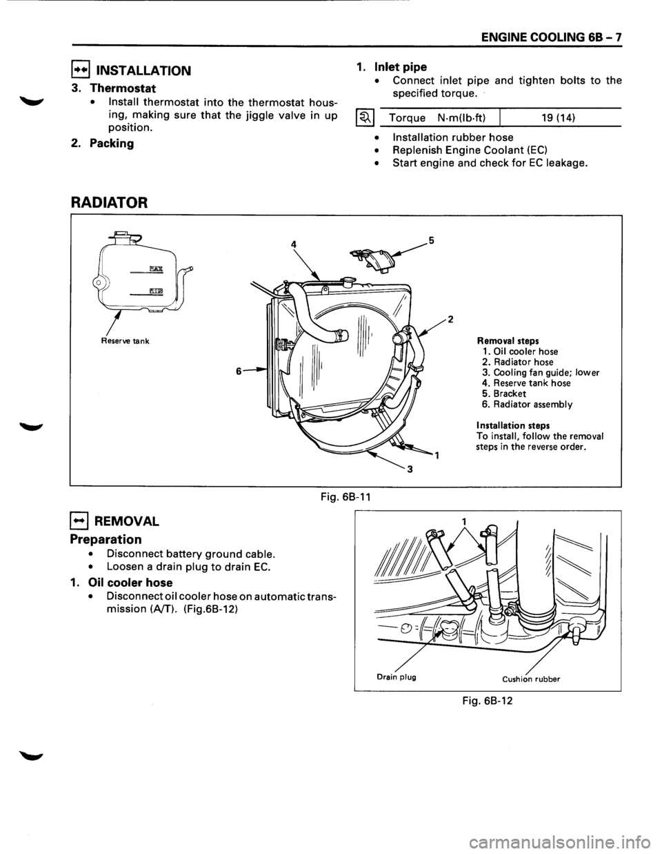
RADIATOR
Reserve tank
6
ENGINE COOLING 68-7
1. Inlet pipe
• Connect inlet pipe and tighten bolts to the
specified torque.
I~~ Torque N·mOb·ft) 19 (14)
• Installation rubber hose
• Replenish Engine Coolant (EC)
• Start engine and check for EC leakage.
2
Removal steps
1.
Oil cooler hose 2. Radiator hose
3. Cooling fan guide; lower
4. Reserve tank hose
5. Bracket
6. Radiator assembly
Installation steps
To install, follow the removal
steps in the reverse order.
Fig. 68-11
EJ REMOVAL
Preparation
• Disconnect battery ground cable.
•
Loosen a drain plug to drain EC.
1. Oil cooler hose
• Disconnect oil cooler hose on automatic trans
mission
(NT). (Fig.68-12)
Drain plug Cushion rubber
Fig. 68-12
Page 636 of 1928
'.,~-' r.
68-8 ENGINE COOLING
2. Radiator hose
• Disconnect inlet hose and outlet hose from the
engine.
3. Fan guide, lower
• Remove clips on both sides and the bottom
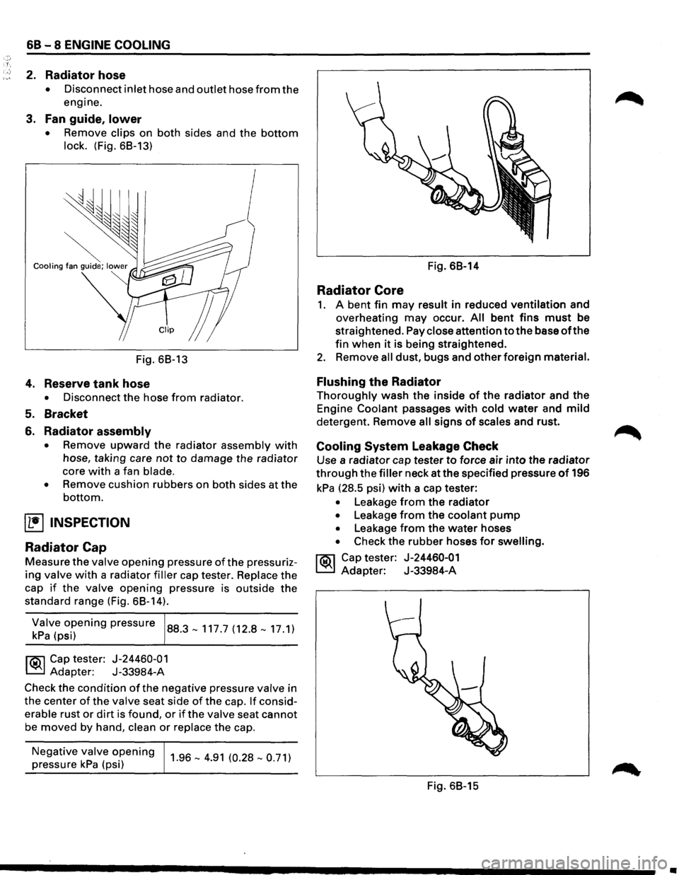
lock. (Fig. 68-13)
~ Cooling fan guide; lower
~
Clip
Fig. 68-13
4. Reserve tank hose
• Disconnect the hose from radiator.
5. Bracket
6. Radiator assembly
• Remove upward the radiator assembly with
hose, taking care not to damage the radiator
core
with a fan blade.
• Remove cushion rubbers on both sides at the
bottom.
~ INSPECTION
Radiator Cap
Measure the valve opening pressure of the pressuriz
ing valve with a radiator filler cap tester. Replace the
cap
if the valve opening pressure is outside the
standard range (Fig. 68-14).
~;!v(~~i~ening pressure 88.3-117.7 (12.8-17.1)
l'i':'il Cap tester: J-24460-01
~ Adapter: J-33984-A
Check the
condition of the negative pressure valve in
the center
of the valve seat side of the cap. If consid
erable rust
or dirt is found, or if the valve seat cannot
be
moved by hand, clean or replace the cap.
Negative
valve opening
pressure kPa (psi) 1.96-4.91 (0.28-0.71)
Fig. 68-14
Radiator Core
1. A bent fin may result in reduced ventilation and
overheating
may occur. All bent fins must be
straightened. Pay
close attention to the base of the
fin when it is being straightened.
2. Remove all dust, bugs and other foreign material.
Flushing the Radiator
Thoroughly wash the inside of the radiator and the
Engine
Coolant passages with cold water and mild
detergent. Remove all signs of scales and rust.
Cooling System Leakage Check
Use a radiator cap tester to force air into the radiator
through the filler neck at the specified pressure of 196
kPa (28.5 psi) with a cap tester:
• Leakage from the radiator
• Leakage from the coolant pump
• Leakage from the water hoses
• Check the rubber hoses for swelling.
rt:\1 Cap tester: J-24460-01
~ Adapter: J-33984-A
Fig. 68-15
•
Page 637 of 1928
E!) INSTALLATION
6. Radiator assembly
• Install cushion rubbers on both sides of radia
tor bottom.
• Install radiator assembly with hose, taking
care
not to damage the radiator core with a fan
blade.
5. Bracket
• Support the radiator uppertankwith the bracket
and secure the radiator.
4. Reserve tank hose
3. Fan guide, lower
2. Radiator hose
• Connect inlet hose and outlet hose to the
engine.
1. Oil cooler hose (A/T)
• Connect oil cooler hose for automatic trans-
mission.
• Connect battery ground cable.
• Pour engine coolant.
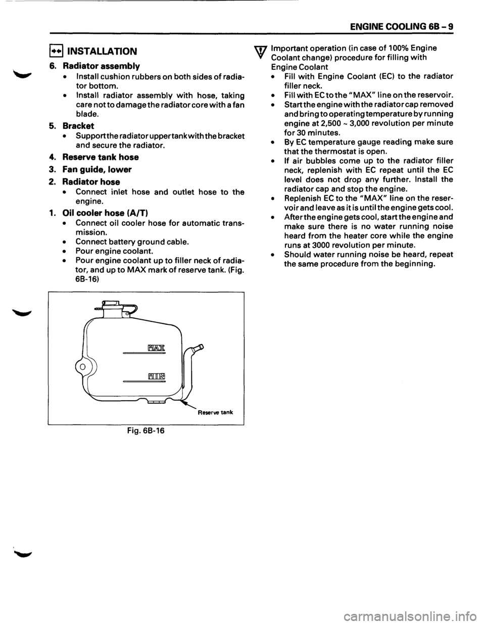
• Pour engine coolant up to filler neck of radia
tor, and up to MAX mark of reserve tank. (Fig.
68-16)
Reserve tank
Fig. 68-16
ENGINE COOLING 68-9
U7 Important operation (in case of 100% Engine
V Coolant change) procedure for filling with
Engine Coolant
• Fill
with Engine Coolant (EC) to the radiator
filler neck.
• Fill with EC to the "MAX" line on the reservoir.
• Start the engine with the radiator cap removed
and bring
to operating temperature by running
engine at
2,500-3,000 revolution per minute
for 30 minutes.
• By EC temperature gauge reading make sure
that the thermostat is open.
• If air bubbles come up to the radiator filler
neck, replenish with EC repeat until the EC
level does not drop any further. Install the
radiator cap and stop the engine.
• Replenish EC to the "MAX" line on the reser
voir and leave as it is until the engine gets cool.
• After the engine gets cool, start the engine and
make sure there is no
water running noise
heard
from the heater core while the engine
runs
at 3000 revolution per minute.
• Should water running noise be heard, repeat
the same procedure from the beginning.
Page 640 of 1928
68 -12 ENGINE COOLING
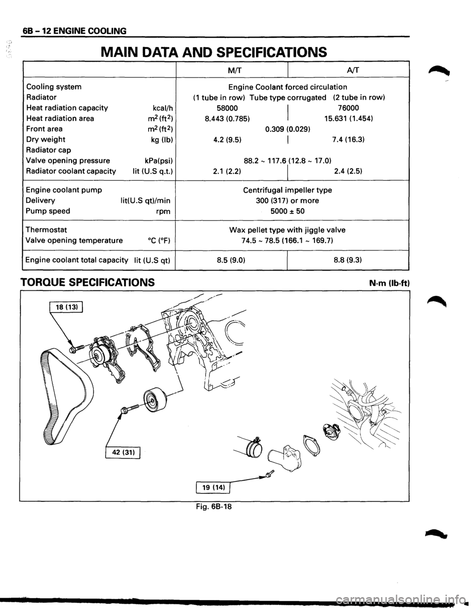
MAIN DATA AND SPECIFICATIONS
M!T I AfT
Cooling system
Engine Coolant forced circulation
Radiator (1 tube in row) Tube type corrugated (2 tube in row)
Heat radiation capacity
kcal/h 58000
I
76000
Heat radiation area m2 (ft2)
8.443 (0.785) 15.631 (1.454)
Front area m2 (ft2) 0.309 (0.029)
Dry weight kg (lb) 4.2 (9.5) I 7.4 (16.3)
Radiator cap
Valve opening pressure kPa(psi) 88.2-117.61(12.8-17.0)
Radiator coolant capacity lit (U.S q.t.) 2.1 (2.2) 2.4 (2.5)
Engine
coolant pump Centrifugal impeller type
Delivery lit(U.S qt)/min 300 (317) or more
Pump speed rpm 5000 ±50
Thermostat Wax pellet type with jiggle valve
Valve
opening temperature oc (oF) 74.5-78.5 (166.1-169.7)
Engine
coolant total capacity lit (U.S qt) 8.5 (9.0) I 8.8
(9.3)
TORQUE SPECIFICATIONS N-m (lb·ft)
Fig. 68-18
..
Page 641 of 1928
ENGINE COOLING 68 -13
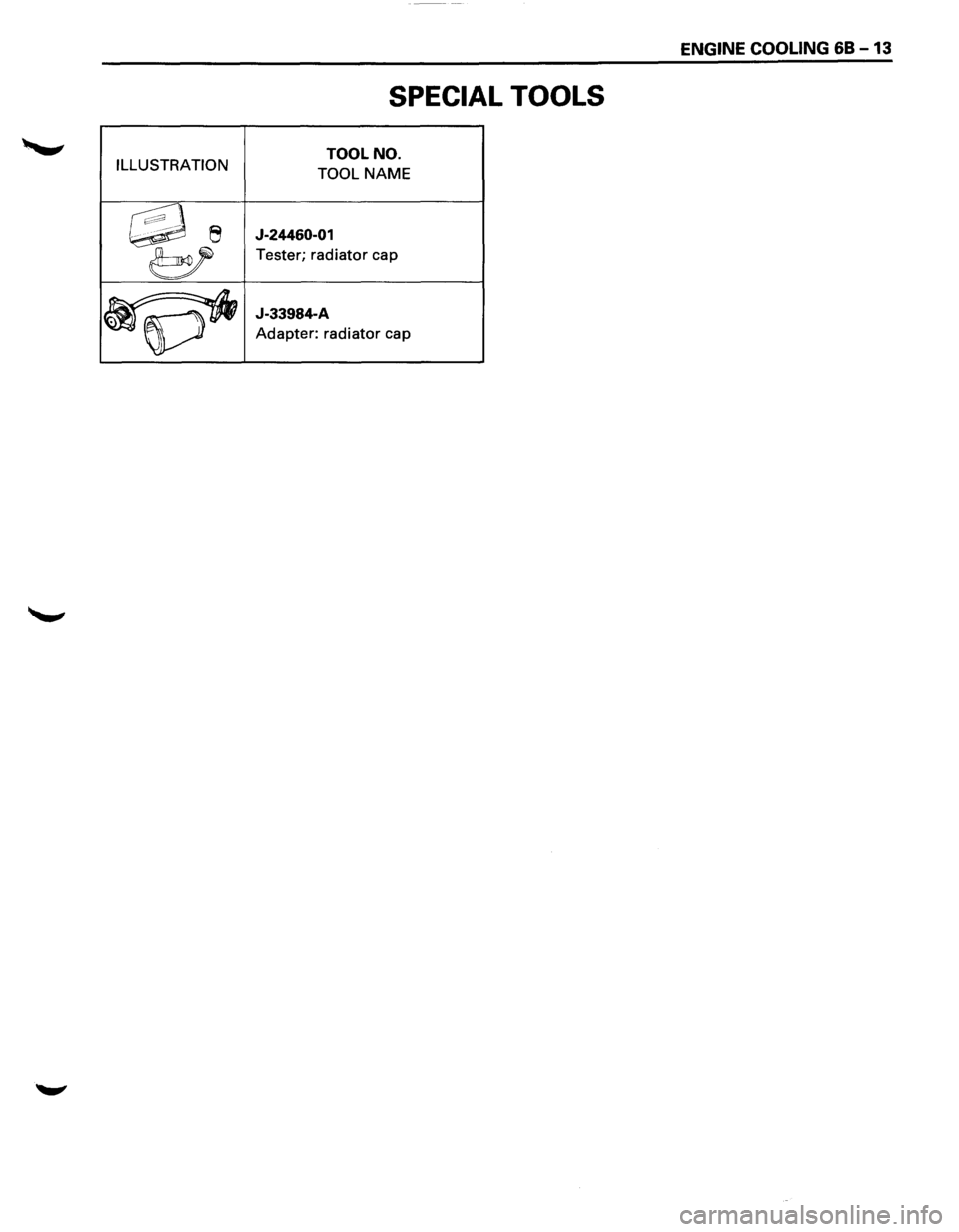
SPECIAL TOOLS
ILLUSTRATION TOOL
NO.
TOOL NAME
~e J-24460-01
e?
Tester; radiator cap
~
J-33984-A
Adapter: radiator cap
Page 718 of 1928
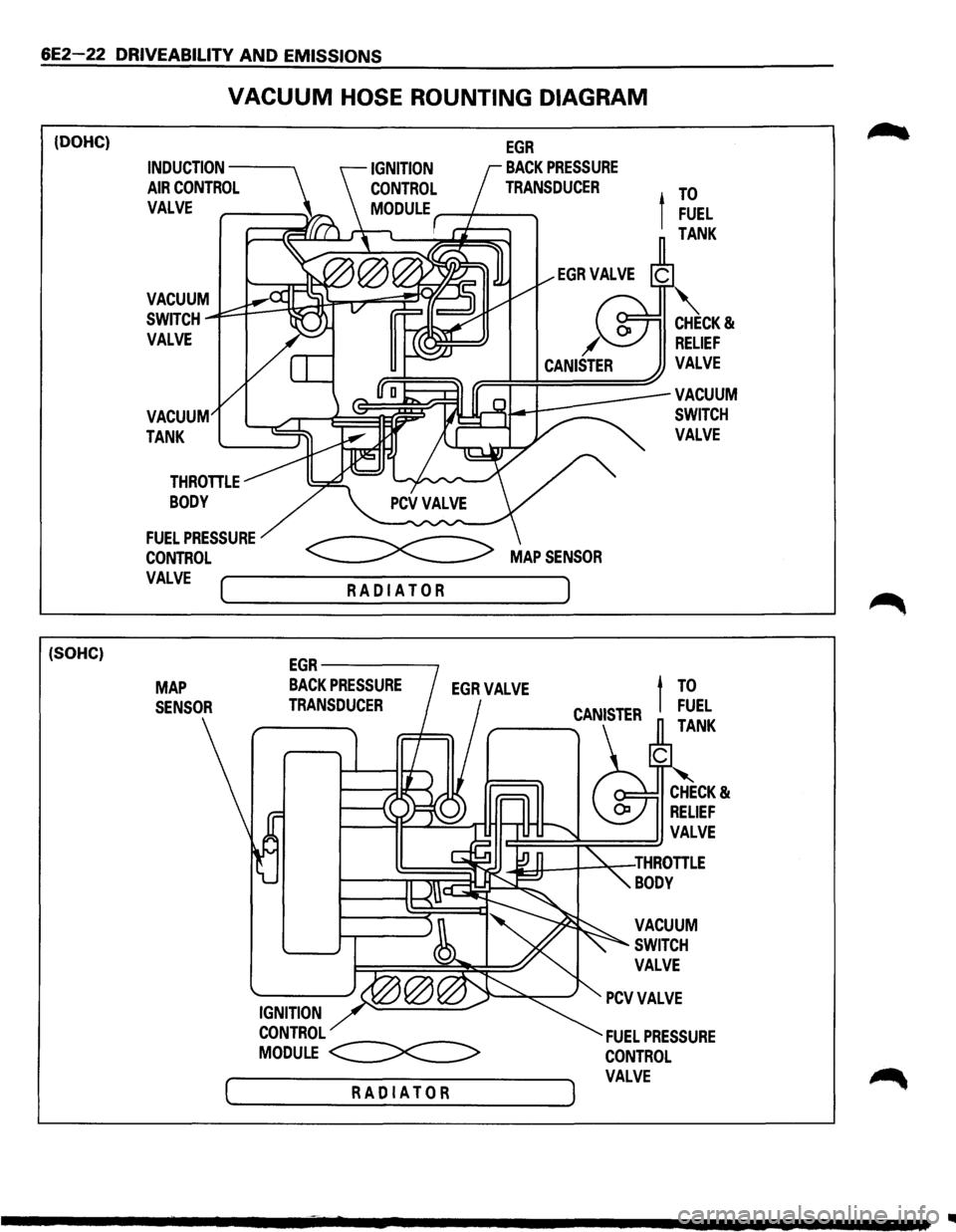
6E2-22 DRIVEABILITV AND EMISSIONS
(DOHC)
(SOHC)
VACUUM HOSE ROUNTING DIAGRAM
EGR
INDUCTION-----
AIR CONTROL
VALVE
BACK PRESSURE
TRANSDUCER
t
TO
THROTTLE
BODY
FUELPRESSURE ~
CONTROL ~ MAPSENSOR
VALVE (..._ _____ R_A_D _I A_T_O_R ____ ___.)
MAP
SENSOR
EGR------,
BACK PRESSURE
TRANSDUCER
FUEL
TANK
VACUUM
SWITCH
VALVE
CHECK&
RELIEF
c:::=::::::::::::::;:T=====!.J VALVE
L-~~~~~ ...J;::...u..-+----'~THROTTLE BODY
IGNITION
CONTROL
MODULE <==><==::>
[ RADIATOR )
~---------------------
VACUUM
SWITCH
VALVE
FUEL PRESSURE
CONTROL
VALVE
..
Page 730 of 1928
6E2-34 DRIVEABILITY AND EMISSIONS
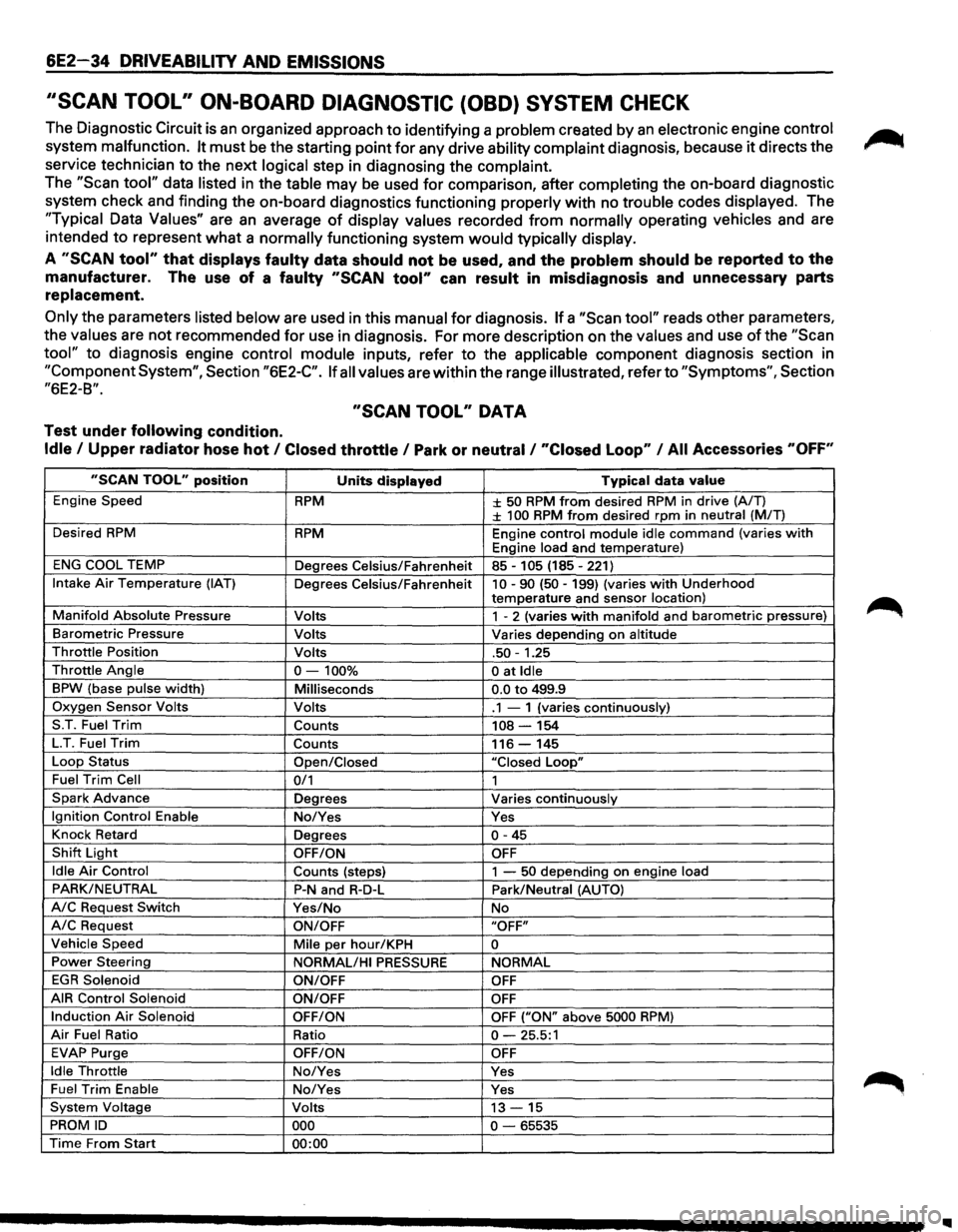
''SCAN TOOL" ON-BOARD DIAGNOSTIC (OBD) SYSTEM CHECK
The Diagnostic Circuit is an organized approach to identifying a problem created by an electronic engine control
system malfunction. It must be the starting point for any drive ability complaint diagnosis, because it directs the
service technician to the next
logical step in diagnosing the complaint.
The "Scan tool" data listed in the table may be used for comparison, after completing the on-board diagnostic
system check and finding the on-board diagnostics functioning
properly with no trouble codes displayed. The
"Typical Data Values" are an average of display values recorded from normally operating vehicles and are
intended
to represent what a normally functioning system would typically display.
A "SCAN tool" that displays faulty data should not be used, and the problem should be reported to the
manufacturer. The use of a faulty "SCAN tool" can result in misdiagnosis and unnecessary parts
replacement.
Only the parameters listed below are used in this manual for diagnosis. If a "Scan tool" reads other parameters,
the
values are not recommended for use in diagnosis. For more description on the values and use of the "Scan
tool" to diagnosis engine control module inputs, refer to the applicable component diagnosis section in
"Component System", Section "6E2-C". If all values are within the range illustrated, refer to "Symptoms", Section
"6E2-B".
"SCAN TOOL" DATA
Test under following condition.
Idle I Upper radiator hose hot I Closed throttle I Park or neutral I "Closed Loop" I All Accessories "OFF"
"SCAN TOOL" position Units displayed Typical data value
Engine Speed RPM ± 50 RPM from desired RPM in drive (A/T) ± 100 RPM from desired rpm in neutral (MIT)
Desired
RPM RPM Engine control module idle command (varies with Engine load and temperature)
ENG COOL TEMP
Degrees Celsius/Fahrenheit 85-105 (185-221)
Intake Air Temperature (IAT) Degrees Celsius/Fahrenheit 10-90 (50-199) (varies with Underhood
temperature and sensor location)
Manifold Absolute Pressure Volts 1 - 2 (varies with manifold and barometric pressure)
Barometric Pressure Volts Varies depending on altitude
Throttle Position Volts .50-1.25
Throttle Angle 0-100% 0 at Idle
BPW (base pulse width) Milliseconds 0.0 to 499.9
Oxygen Sensor Volts Volts .1 - 1 (varies continuously)
S.T. Fuel
Trim Counts 108-154
LT. Fuel Trim Counts 116-145
Loop Status
Open/Closed "Closed Loop"
Fuel Trim Cell 0/1 1
Spark Advance Degrees Varies continuously
Ignition Control Enable No/Yes Yes
Knock Retard
Degrees
0-45
Shift Light OFF/ON OFF
Idle Air Control
Counts (steps) 1 -50 depending on engine load
PARK/NEUTRAL P-N and R-D-L Park/Neutral (AUTO)
A/C Request Switch Yes/No No
A/C Request ON/OFF "OFF"
Vehicle Speed
Mile per hour/KPH 0
Power Steering
NORMAL/HI PRESSURE NORMAL
EGR Solenoid
ON/OFF OFF
AIR Control Solenoid
ON/OFF OFF
Induction Air Solenoid OFF/ON OFF ("ON" above 5000 RPM)
Air Fuel Ratio Ratio 0-25.5:1
EVAP Purge OFF/ON OFF
Idle Throttle No/Yes Yes
Fuel Trim Enable No/Yes Yes
System Voltage Volts 13-15
PROM ID 000 0-65535
Time From Start 00:00
Page 788 of 1928
6E2-92 DRIVEABILITY AND EMISSIONS
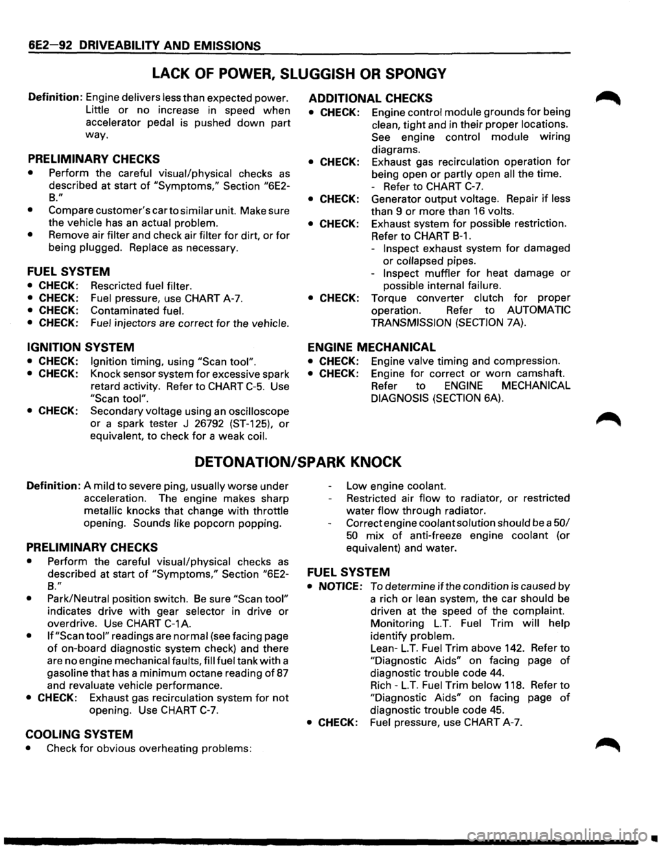
LACK OF POWER, SLUGGISH OR SPONGY
Definition: Engine delivers less than expected power.
Little or no increase in speed when
accelerator
pedal is pushed down part
way.
PRELIMINARY CHECKS
• Perform the careful visual/physical checks as
described at start of "Symptoms," Section "6E2-
B."
•
Compare customer's car to similar unit. Make sure
the
vehicle has an actual problem.
• Remove air filter and check air filter for dirt, or for
being plugged. Replace as necessary.
FUEL SYSTEM
• CHECK: Rescricted fuel filter.
• CHECK: Fuel pressure, use CHART A-7.
• CHECK: Contaminated fuel.
• CHECK: Fuel injectors are correct for the vehicle.
IGNITION SYSTEM
• CHECK: Ignition timing, using "Scan tool".
• CHECK: Knock sensor system for excessive spark
retard activity. Refer to CHART
C-5. Use
"Scan tool".
• CHECK: Secondary voltage using an oscilloscope
or a spark tester J 26792 (ST-125), or
equivalent, to check for a weak coil.
ADDITIONAL CHECKS
• CHECK: Engine control module grounds for being
clean,
tight and in their proper locations.
See engine control module wiring
diagrams.
• CHECK: Exhaust gas recirculation operation for
being open or partly open all the time.
- Refer to CHART
C-7.
• CHECK: Generator output voltage. Repair if less
than 9
or more than 16 volts.
• CHECK: Exhaust system for possible restriction.
Refer
to CHART B-1.
-Inspect exhaust system for damaged
or collapsed pipes.
-
Inspect muffler for heat damage or
possible internal failure.
• CHECK: Torque converter clutch for proper
operation. Refer
to AUTOMATIC
TRANSMISSION
(SECTION 7A).
ENGINE MECHANICAL
• CHECK: Engine valve timing and compression.
• CHECK: Engine for correct or worn camshaft.
Refer
to ENGINE MECHANICAL
DIAGNOSIS
(SECTION 6A).
DETONATION/SPARK KNOCK
Definition: A mild to severe ping, usually worse under
acceleration. The engine makes sharp
metallic knocks that change with throttle
opening.
Sounds like popcorn popping.
PRELIMINARY CHECKS
• Perform the careful visual/physical checks as
Low engine coolant.
Restricted air
flow to radiator, or restricted
water flow through radiator.
Correct engine
coolant solution should be a 50/
50 mix of anti-freeze engine coolant (or
equivalent) and water.
described at start
of "Symptoms," Section "6E2-FUEL SYSTEM
B."
•
Park/Neutral position switch. Be sure "Scan tool"
indicates drive with gear selector in drive or
overdrive. Use
CHART C-1A.
• If "Scan tool" readings are normal (see facing page
of on-board diagnostic system check) and there
are no engine mechanical faults,
fill fuel tank with a
gasoline
that has a minimum octane reading of 87
and revaluate vehicle performance.
• CHECK: Exhaust gas recirculation system for not
opening. Use CHART C-7.
COOLING SYSTEM
• Check for obvious overheating problems:
• NOTICE: To determine if the condition is caused by
a rich
or lean system, the car should be
driven at the speed
of the complaint.
Monitoring
LT. Fuel Trim will help
identify problem.
Lean-
LT. Fuel Trim above 142. Refer to
"Diagnostic Aids" on facing page of
diagnostic trouble code 44.
Rich-LT. Fuel Trim below 118. Refer to
"Diagnostic Aids" on facing page of
diagnostic trouble code 45.
• CHECK: Fuel pressure, use CHART A-7.
..
Page 893 of 1928
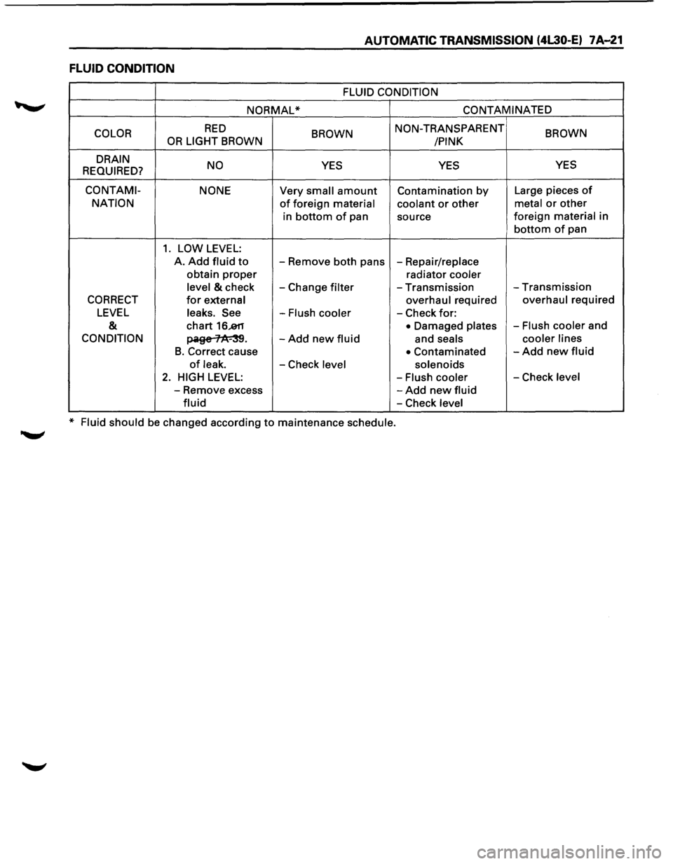
AUTOMATIC TRANSMISSION (4L30-E) 7A-21
FLUID CONDITION
FLUID CONDITION
NORMAL* CONTAMINATED
COLOR
RED BROWN NON-TRANSPARENT BROWN OR LIGHT BROWN
/PINK
DRAIN NO
YES YES YES
REQUIRED?
CO NT AMI- NONE Very small amount Contamination by Large pieces of
NATION of foreign material coolant or other metal or other
in bottom of pan
source foreign material in
bottom of pan
1. LOW LEVEL:
A. Add fluid to -
Remove both pans -Repair/replace
obtain
proper radiator cooler
level
& check -Change filter -Transmission -Transmission
CORRECT for external overhaul required overhaul required
LEVEL leaks. See -Flush cooler -Check for:
& chart 16..811 • Damaged plates -Flush cooler and
CONDITION ~· -Add new fluid and seals cooler
lines
B. Correct cause • Contaminated -Add new fluid
of leak. -Check level solenoids
2. HIGH LEVEL: -Flush cooler -Check level
-Remove excess -Add new fluid
fluid -Check level
* Fluid should be changed according to maintenance schedule.
Page 1030 of 1928
7A-158 AUTOMATIC TRANSMISSION (4L30-E)
1. Mode switch cover
2.
Selector lever
• Disconnect selector lever from the mode
switch.
3. Heat protector
• Remove heat protector from the converter
housing. (Fig. 7A-18).
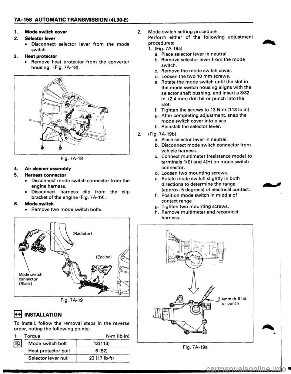
Fig. 7A-18
4. Air cleaner assembly
5. Harness connector
• Disconnect mode switch connector from the
engine harness.
• Disconnect harness clip from the clip
bracket ofthe engine (Fig. 7A-19).
6. Mode switch
• Remove two mode switch bolts.
Mode switch
connector
(Black)
(Radiator)
(Engine)
Fig. 7A-19
I••! INSTALLATION
To install, follow the removal steps in the reverse
order,
noting the following points;
1. Torque
~~~ Mode switch bolt
Heat protector bolt
Selector lever nut
N·m Ob·in)
13(113)
6 (52)
23 ( 17 lb·ft)
2. Mode switch setting procedure
Perform either
of the following adjustment
procedures:
1. (Fig. 7A-19a)
a. Place selector lever in neutral.
b. Remove selector lever from the mode
switch.
c. Remove the mode switch cover.
d. Loosen the
two 10 mm screws.
e. Rotate the mode switch until the slot in
the mode switch housing aligns with the
selector shaft bushing, and insert a 3/32
in. (2.4
mm) drill bit or punch into the
sllot.
f. Tighten the screws to 13 N·m (113 lb·in).
g. After completing adjustment, snap the
mode switch cover into place.
h. Reinstall the selector lever.
2. (Fig. 7 A.-19b)
a. Place selector lever in neutral.
b. Disconnect mode switch connector from
vehicle harness.
c. Connect multimeter (resistance mode) to
terminals 1(E) and 4(H) on mode switch
connector.
d.
Loosen two mounting screws.
e. Rotate mode switch slightly in both
diirections to determine the range
(approx.
5 degrees) of electrical contact.
f. Position
mode switch in middle of
contact range.
g. Tighten
two mounting screws.
h. Remove multimeter and reconnect
harness.
Fig. 7A-19a
..
•