belt ISUZU TROOPER 1995 Manual PDF
[x] Cancel search | Manufacturer: ISUZU, Model Year: 1995, Model line: TROOPER, Model: ISUZU TROOPER 1995Pages: 1928
Page 1636 of 1928
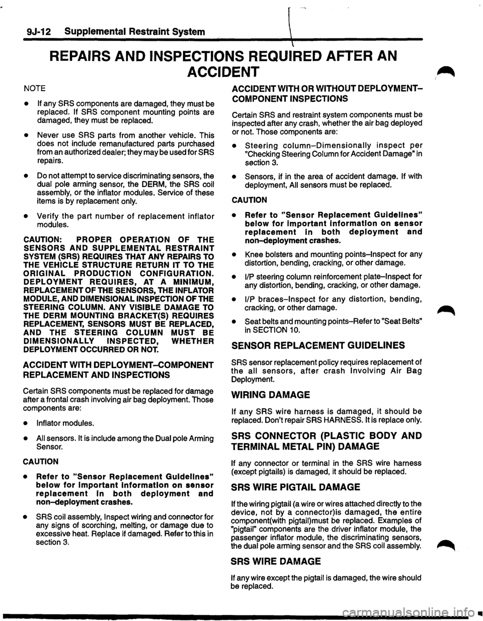
9J-12 Supplemental Restraint System
REPAIRS AND INSPECTIONS REQUIRED AFTER AN
ACCIDENT
NOTE
• If
any SRS components are damaged, they must be
replaced. If SRS component mounting points are
damaged, they must be
replaced.
•
Never use SRS parts from another vehicle. This
does not
include remanufactured parts purchased
from an authorized
dealer; they may be used for SRS
repairs.
• Do not attempt to service discriminating sensors, the
dual pole arming sensor, the DERM, the SRS coil
assembly,
or the inflator modules. Service of these
items is by
replacement only.
•
Verify the part number of replacement inflator
modules.
CAUTION: PROPER OPERATION OF THE
SENSORS AND SUPPLEMENTAL RESTRAINT
SYSTEM (SRS) REQUIRES THAT ANY REPAIRS TO
THE VEHICLE STRUCTURE RETURN IT TO THE
ORIGINAL PRODUCTION CONFIGURATION.
DEPLOYMENT REQUIRES, AT A MINIMUM,
REPLACEMENT OF THE SENSORS, THE INFLATOR
MODULE,
AND DIMENSIONAL INSPECTION OF THE
STEERING COLUMN. ANY VISIBLE DAMAGE TO
THE DERM MOUNTING BRACKET(S) REQUIRES
REPLACEMENT, SENSORS MUST BE REPLACED,
AND THE
STEERING COLUMN MUST BE
DIMENSIONALLY INSPECTED, WHETHER
DEPLOYMENT
OCCURRED OR NOT.
ACCIDENT WITH DEPLOYMENT-COMPONENT
REPLACEMENT AND
INSPECTIONS
Certain SRS components must be replaced for damage
after a
frontal crash involving air bag deployment. Those
components are:
• Inflator modules.
• All
sensors. It is include among the Dual pole Arming
Sensor.
CAUTION
•
Refer to "Sensor Replacement Guidelines"
below for Important Information on sensor
replacement In both deployment and
non-deployment crashes.
• SRS coil assembly, Inspect wiring and connector for
any signs of scorching,
melting, or damage due to
excessive heat.
Replace if damaged. Refer to this in
section
3.
ACCIDENT WITH OR WITHOUT DEPLOYMENT
COMPONENT INSPECTIONS
Certain SRS and restraint system components must be
inspected after any crash, whether the air bag
deployed
or not. Those components are:
• Steering column-Dimensionally inspect per
"Checking Steering Column for Accident Damage" in
section 3.
• Sensors, if in the area of accident damage. If with
deployment, All sensors must be replaced.
CAUTION
•
Refer to "Sensor Replacement Guidelines"
below for Important information on sensor
replacement in both deployment and
non-deployment crashes.
• Knee bolsters and mounting points-Inspect for any
distortion, bending, cracking, or other damage.
• 1/P steering column reinforcement plate-Inspect for
any distortion, bending, cracking, or other damage.
• liP braces-Inspect for any distortion, bending,
cracking, or other damage.
~
• Seat belts and mounting points-Refer to "Seat Belts"
in SECTION 10.
SENSOR REPLACEMENT GUIDELINES
SRS sensor replacement policy requires replacement of
the all sensors, after crash Involving Air Bag
Deployment.
WIRING DAMAGE
If any SRS wire harness is damaged, it should be
replaced. Don't repair SRS HARNESS. It is replace only.
SRS CONNECTOR {PLASTIC BODY AND
TERMINAL METAL PIN) DAMAGE
If any connector or terminal in the SRS wire harness
(except
pigtails) is damaged, it should be replaced.
SRS WIRE PIGTAIL DAMAGE
If the wiring pigtail (a wire or wires attached directly to the
device,
not by a connector)is damaged, the entire
component(with pigtail)must be replaced. Examples of
"pigtail" components are the driver inflator module, the
passenger
inflator module, the discriminating sensors,
the
dual pole arming sensor and the SRS coil assembly. ~
SRS WIRE DAMAGE
If any wire except the pigtail is damaged, the wire should
be replaced.
Ill
Page 1690 of 1928
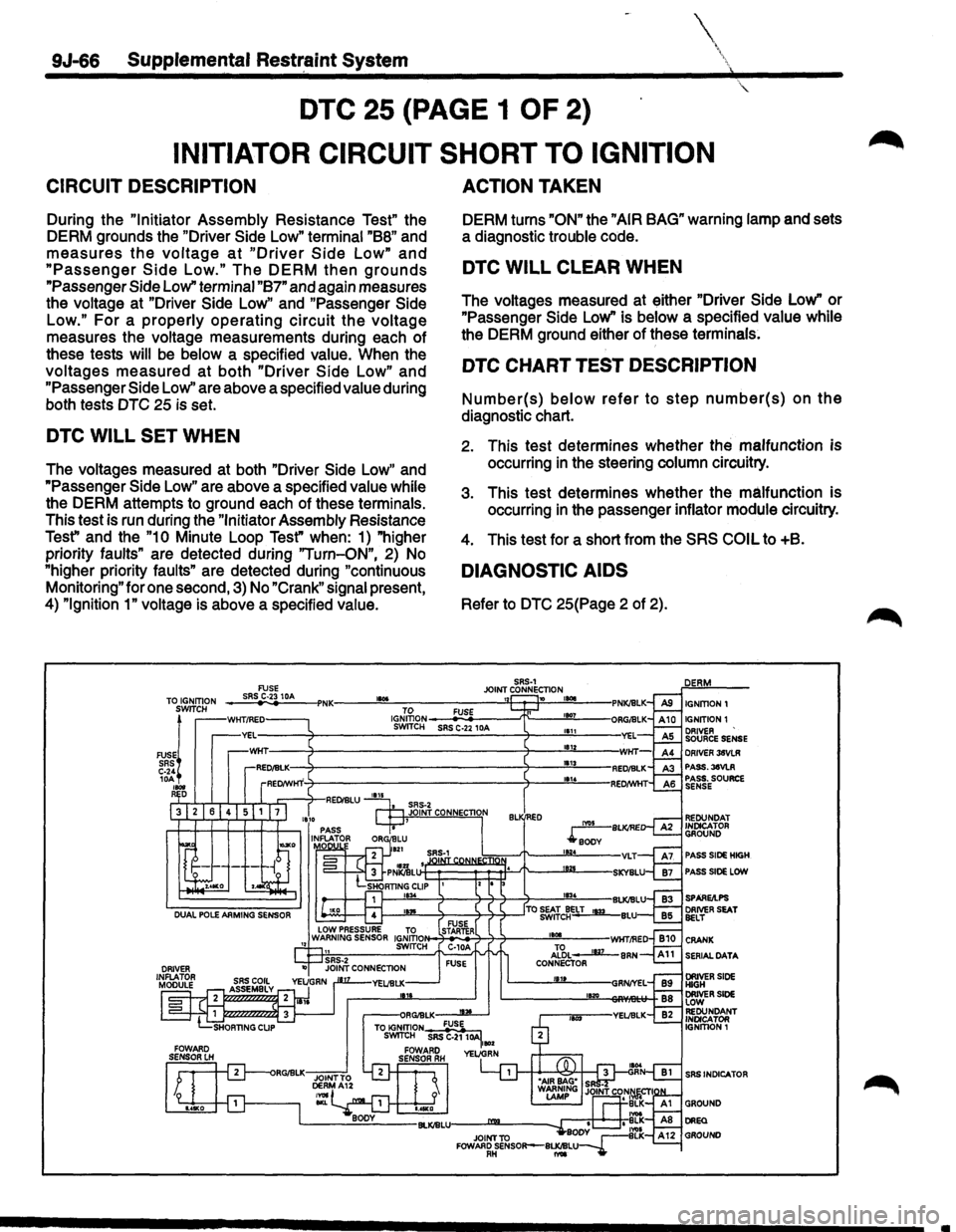
9J-66 Supplemental Restr.aint System
DTC 25 (PAGE 1 OF 2)
INITIATOR CIRCUIT SHORT TO IGNITION
CIRCUIT DESCRIPTION
During the "Initiator Assembly Resistance Test" the
DERM grounds the
"Driver Side Low" terminal "BB" and
measures the voltage at "Driver Side Low" and
"Passenger Side Low." The DERM then grounds
"Passenger Side Low" terminal "B7" and again measures
the
voltage at "Driver Side Low" and "Passenger Side
Low."
For a properly operating circuit the voltage
measures the voltage measurements during each of
these tests
will be below a specified value. When the
voltages measured at both "Driver Side Low" and
"Passenger
Side Low'' are above a specified value during
both tests
DTC 25 is set.
DTC WILL SET WHEN
The voltages measured at both "Driver Side Low" and
"Passenger
Side Low" are above a specified value while
the DERM attempts to ground each of these terminals.
This test is run during the
"Initiator Assembly Resistance
Test" and the "1 0 Minute Loop Test" when: 1) "higher
priority
faults" are detected during ''Turn-ON", 2) No
"higher priority
faults" are detected during "continuous
Monitoring" for one second, 3) No
"Crank" signal present,
4)
"Ignition 1" voltage is above a specified value.
ACTION TAKEN
DERM turns "ON" the "AIR BAG" warning lamp and sets
a diagnostic
trouble code.
DTC WILL CLEAR WHEN
The voltages measured at either "Driver Side Low" or
"Passenger
Side Low" is below a specified value while
the DERM ground either of these terminals.
DTC CHART TEST DESCRIPTION
Number(s) below refer to step number(s) on the
diagnostic chart.
2. This test determines whether the malfunction is
occurring
in the steering column circuitry.
3. This test determines whether the malfunction is
occurring
in the passenger inflator module circuitry.
4. This test for a short from the SRS COIL to +B.
DIAGNOSTIC AIDS
Refer to DTC 25(Page 2 of 2).
IGNmON 1 IGNITION 1 DRIVER SOURCE SENSE
~ -
DRIVER 38VLR PASS. 38VLR PASS. SOURCE SENSE 1DA 1&14 111011 D
REDUNDAT INDICATOR GROUND
PASS SIDE HIGH
PASS SIDE LOW
SPARE/l.PS DRIVER SEAT BelT
SERIAL DATA
SRS INDICATOR
Page 1706 of 1928
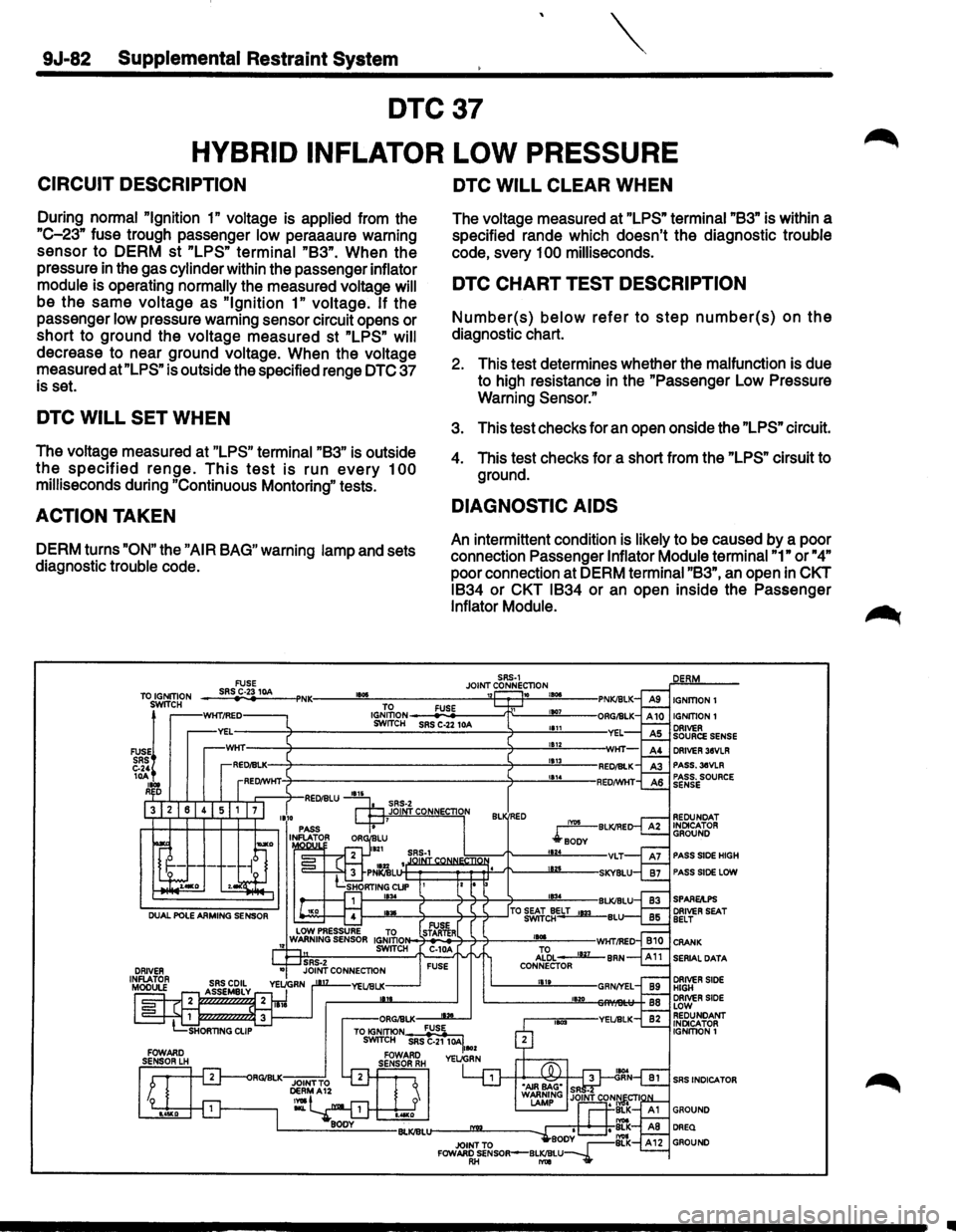
9J·82 Supplemental Restraint System
DTC37
HYBRID INFLATOR LOW PRESSURE
CIRCUIT DESCRIPTION
During normal "Ignition 1" voltage is applied from the
"C-23" fuse trough passenger low peraaaure warning
sensor to DERM st
"LPS" terminal "83". When the
pressure in the gas cylinder within the passenger inflator
module is operating normally the measured voltage will
be the same voltage as "Ignition 1" voltage. If the
passenger
low pressure warning sensor circuit opens or
short to ground the voltage measured st
"LPS" will
decrease to near ground voltage. When the voltage
measured
at"LPS" is outside the specified renge DTC 37
is set.
DTC WILL SET WHEN
The voltage measured at "LPS" terminal "83" is outside
the specified renge. This test is run every 100
milliseconds during "Continuous Montoring" tests.
ACTION TAKEN
DERM turns "ON" the "AIR BAG" warning lamp and sets
diagnostic trouble code.
DTC WILL CLEAR WHEN
The voltage measured at "LPS" terminal "83" is within a
specified rande which doesn't the diagnostic trouble
code, svery
100 milliseconds.
DTC CHART TEST DESCRIPTION
Number(s) below refer to step number(s) on the
diagnostic chart.
2. This test determines whether the malfunction is due
to high resistance
in the "Passenger Low Pressure
Warning
Sensor."
3. This test checks for an open onside the "LPS" circuit.
4. This test checks for a short from the "LPS" cirsuit to
ground.
DIAGNOSTIC AIDS
An intermittent condition is likely to be caused by a poor
connection Passenger
Inflator Module terminal "1" or "4"
poor connection at DERM terminal "83", an open in CKT
1834 or CKT 1834 or an open inside the Passenger
Inflator Module.
SRS-1 JOINT CONNECTION 10 , ... IGNITION!
IGNITION 1 ORIVER SOURCE SENSE DRIVER 38VLR PASS.3eVLR PASS. SOURCE SENSE
REDUNDAT INDICATOR GROUND
PASS SIDE HIGH
PASS SIDE LOW
SPARE/I.PS DRIVER SEAT BELT
SERIAL DATA
DRIVER SIDE HIGH DRIVER SIDE LOW REDUNDANT INDICATOR IGNITION!
SRS INDICATOR
..
Page 1716 of 1928
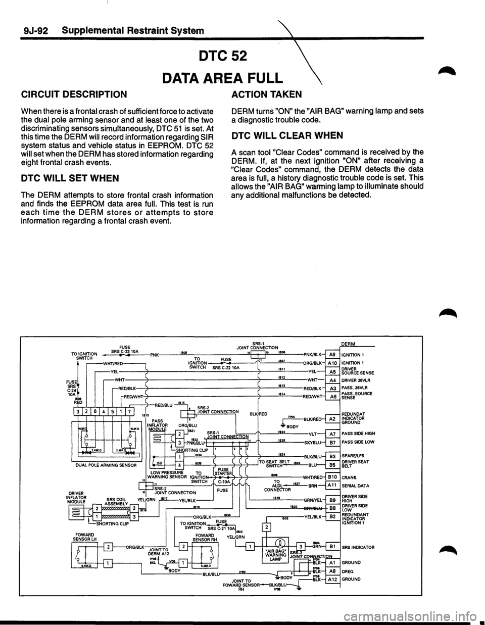
9J-92 Supplemental Restraint System
DTC52
CIRCUIT DESCRIPTION
DATA AREA FULL
ACTION TAKEN
When there is a frontal crash of sufficient force to activate
the dual pole arming sensor and at least one of the two
discriminating sensors simultaneously,
DTC 51 is set. At
this time the DERM
will record information regarding SIR
system status and vehicle status in EEPROM. DTC 52
will set when the DERM has stored information regarding
eight frontal crash events.
DTC WILL SET WHEN
The DERM attempts to store frontal crash information
and finds the
EEPROM data area full. This test is run
each time the DERM stores or attempts to store
information regarding a frontal crash event. DERM
turns
"ON" the "AIR BAG" warning lamp and sets
a diagnostic trouble code.
DTC WILL CLEAR WHEN
A scan tool "Clear Codes" command is received by the
DERM.
If, at the next ignition "ON" after receiving a
"Clear Codes" command, the DERM detects the data
area is
full, a history diagnostic trouble code is set. This
allows the "AIR BAG" warming lamp to illuminate should
any additional malfunctions be detected.
SRS·1 FUSE JOINT CONNECTION TO IGNITION SWITCH
FUSE! SRS C·2' 10A 1101 R D
--~SR~S~C~·23~1~0A~-IPNK----~~~~~------------_sn~~»~~~~·~~---l IGJ;~ON __ __.:FU:;:Si-E ____ _.fr;:--___ 1!!!107!!...-___ SWITCH SAS C·22 1 OA
FUSE STARTER 1801
Al~L • 1127 CONNECTOR 1111
1!120
IGNITION1
IGNITION1
DRIVER SOURCE SENSE DRIVER 36VLR PASS. 3SVLR PASS. SOURCE SENSE
REDUNDAT INDICATOR
GROUND
PASS SIDE HIGH
PASS SIDE LOW
SPARQPS DRIVER SEAT BELT
CRANK
SERIAL
DATA
DRIVER SIDE HIGH DRIVER SIDE LOW REDUNDANT INDICATOR
IGNITION 1
SRS INDICATOR
•
Page 1726 of 1928
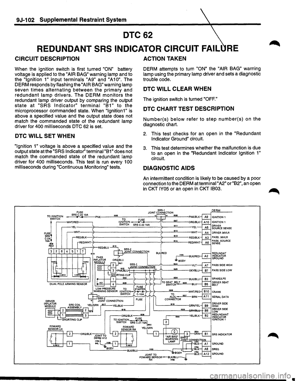
9J-102 Supplemental Restraint System
DTC62
REDUNDANT SRS INDICATOR CIRCUIT FAIL RE
CIRCUIT DESCRIPTION
When the ignition switch is first turned "ON" battery
voltage is applied to the
"AIR BAG" warning lamp and to
the
"Ignition 1" input terminals "A9" and "A10". The
DERM responds by flashing the
"AIR BAG" warning lamp
seven
times alternating between the primary and
redundant lamp drivers. The DERM monitors the
redundant lamp driver output by comparing the output
state at "SRS Indicator" terminal "B1" to the
microprocessor commanded state. When
"lgnition1" is
above a specified value and the output state does not
match the commanded state of the redundant lamp
driver for
400 milliseconds DTC 62 is set.
DTC WILL SET WHEN
"Ignition 1" voltage is above a specified value and the
output state at the
"SRS Indicator'' terminal "B 1" does not
match the commanded state of the redundant lamp
driver for
400 milliseconds. This test is run every 100
milliseconds during "Continuous Monitoring" tests.
FUSE
ACTION TAKEN
DERM attempts to turn "ON" the "AIR BAG" warning
lamp using the primary lamp driver and sets a diagnostic
trouble code.
DTC WILL CLEAR WHEN
The ignition switch is turned "OFF."
DTC CHART TEST DESCRIPTION
Number(s) below refer to step number(s) on the
diagnostic chart.
2. This test checks for an open in the "Redundant
Indicator Ground"
circuit.
3. This test determines whether the malfunction is due
to
an open in the "Redundant Indicator Ignition 1"
circuit.
DIAGNOSTIC AIDS
An intermittent condition is likely to be caused by a poor
connection to the DERM at terminal
"A2" or "B2", an open
in
CKT IY05 or an open in CKT IB03.
SRS-1 JOINT CONNECTION ___ sR~SrC~·23~1_M ___ ,PNK:----~"~~------------~"~~~~18~~~--TO IGNITION SWITCH IGNITION 1
FUSE!
SRS C-24 lOA 1800 RED
WKT/RED IGJ~oN ---
PASS SIDE HIGH
PASS SIDE LOW
DRIVER SEAT BELT
CRANK
SERIAL DATA
DRIVER SIDE HIGH DRIVER SIDE LOW REDUNDANT INDICATOR
IGNITION 1
SRS INDICATOR
Page 1742 of 1928
9J-118 Supplemental Restraint System
attachments
- Driver seat and belt
- Passenger seat and belt
- Dual Pole Arming
Sensor
-Discriminating Sensors
-DERM
The sensor replacement policy specifies mandatory
replacement of the sensors, after crash involving
AIR
BAG deployment. If AIR BAG has not been deployd,
Replace the sensors
in the area of accident damage only.
The
"area of accident damage" is defined as that area of
the vehicle which is crushed, bent ,or damaged in other
ways. An example might be a front-end collision
in which
the forward portions of the vehicle have contacted
another vehicle, tree, guardrail,etc.
In this example,
1)
If AIR BAG has deployed, All Sensor should be
replaced.
2)
If AIR BAG has not deployed, replace the sensors
in the area of accident damage only.
sensor(s) on the radiator tie bar would require
replacement, since that portion of the vehicle was
damaged in the accident. The Dual Pole Arming Sensor
would not require mandatory replacement. Of course, if
the DERM sets a code and the diagnostic chart leads to
a faulty sensor that was not in the area of accident
damage, that sensor should also be replaced.Sensors
in
the area of accident damage should be replaced even if
those sensors do not appear to be damaged. Do not
attempt to determine whether a sensor is
OK-ALWAYS
replace it if it is in the area of accident damage.Aiso, if a
sensor is
in an area of accident damage,but the SRS has
NOT been deployed,replace the sensor.The sensor
bracket may be slightly bent,wiring may be
damaged, etc., and the sensor might not work properly
in
another collision. Again, do not attempt to determine
whether a sensor is
OK --ALWAYS replace it if it is in
the area of accident damage. Also,
inspect
SRS coil assembly wiring and steering
wheel for any signs of scorching, melting, or damage due
to excessive heat.
If the coil assembly wire or steering ~
wheel is damaged, replace them. The steering column
and wheel must be dimensionally checked to determine
if they are damaged. Refer to
in this Section 3 of this
manual.
Never use
SRS parts from another vehicle. This does not
include remanufactured parts purchased from an
authorized
ISUZU Dealer; they may be used for SRS
repairs.
Do not attempt to repair the forward discriminating
sensors ,the dual pole arming senor, the DERM, the
SRS
coil assembly, the inflator modules, the steering wheel, or
the steering column. Service of these items is
replacement only.
Verify replacement part numbers.
CAUTION: PROPER OPERATION OF THE
SENSORS AND SUPPLEMENTAL RESTRAINT
SYSTEM(SRS)REQUIRES THAT ANY REPAIRS TO
THE VEHICLE STRUCTURE RETURN IT TO ITS
ORIGINAL PRODUCTION CONFIGURATION.
II
Page 1760 of 1928
10-2 BODY
Tailgate Center Weatherstrip ...... 10-84 Sun Roof Glass ................... 10-113
Tailgate Main Weatherstrip ....... 10-85
Spare Tire Carrier
............... 10-85
Sun Roof Deflector ................ 10-114
Sunshade ....................... 10-115 ~
Seats ........................... 10-86 Sun Roof Frame Complete
Front Seat Assembly ............ 10-86 Assembly ...................... 10-116
Rear Seat Assembly ............. 10-96 Sun Roof Drain Hose ............ 10-119
Rear Seat Foot Rest (L·W·B) ...... 10-101 Rear Air Deflector ............... 10-122
Luggage Floor Box (L·W·B) ........... 10-101 Roof Moulding ................. 10-124
Rope Hook Set ................... 10-102 Stationary Glass .................. 10-127
Seat
Belt .......................... 10-103 Windshield ..................... 10-127
Front Seat Belt ................... 10-103 Rear Quarter Side Glass .......... 10-130
Front Seat Buckle Assembly ........ 10-105 Tailgate Glass .................. 10-132
Rear Seat Belt .................... 10-106 Child Restraint ................... 10-134
Reat Center Seat Belt (S·W·B) ....... 10-108 Child Seat Tether Anchor Bracket .. 10-134
Rear Center Seat Belt/Buckle Key ............................ 10-135
Assembly ...................... 10-108 Key
Coding .................... 10-135
Rear Seat Lock Assembly .......... 10-109 Key Styles ..................... 10-135
Rear Seat Striker ................. 10-110 Main Data and Specifications ......... 10-136
Roof ............................ 10-111 Torque Specifications .............. 10-136
Headlining ....................... 10-111 Special Tools ....................... 10-146
GENERAL DESCRIPTION
This section describes major items of the removal,
installation
and servicing procedures pertaining to
TROOPER body. Each servicing instruction is
applicable to all models of TROOPER, unless
otherwise specifically mentioned. For those
differing by specific models from the common
procedures, they are detailed for each model.
..
Page 1814 of 1928
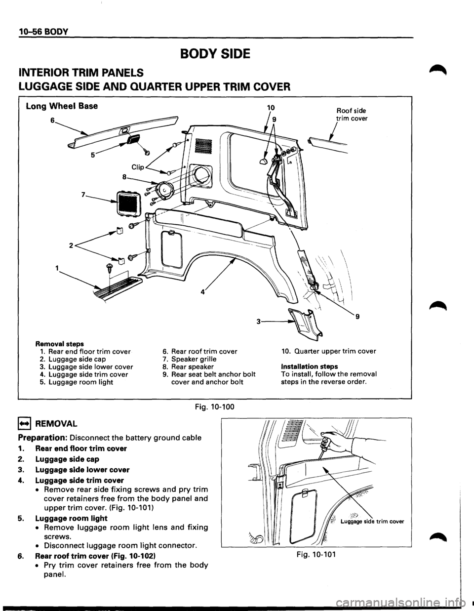
10-56 BODY
BODY SIDE
INTERIOR TRIM PANELS
LUGGAGE
SIDE AND QUARTER UPPER TRIM COVER
Long Wheel Base
6
1
Removal steps 1. Rear end floor trim cover 2. Luggage side cap 3. Luggage side lower cover 4. Luggage side trim cover 5. Luggage room light
1+•1 REMOVAL
6. Rear roof trim cover
7. Speaker grille 8. Rear speaker 9. Rear seat belt anchor bolt cover and anchor bolt
Fig. 10-100
Preparation: Disconnect the battery ground cable
1. Rear end floor trim cover
2. Luggage side cap
3. Luggage side lower cover
4. Luggage side trim cover
• Remove rear side fixing screws and pry trim
cover retainers free from the body panel and
upper trim cover. (Fig. 10-101)
5. Luggage room light
• Remove luggage room light lens and fixing
screws.
• Disconnect luggage room light connector.
6. Rear roof trim cover (Fig. 10-102)
• Pry trim cover retainers free from the body
panel.
Roof side trim cover
, _ _.,,..~
~
9
10. Quarter upper trim cover
Installation steps
To install, follow the removal
steps in
the reverse order.
~~F:r Luggage side trim cover
Fig. 10-101
•
Page 1815 of 1928
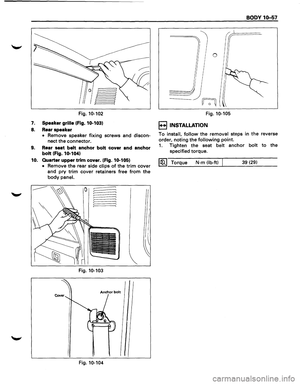
Fig. 10-102
7. Speaker grille (Fig. 10-103)
8. Rear speaker
• Remove speaker fixing screws and discon
nect
the connector.
9. Rear seat belt anchor bolt cover and anchor
bolt
(Fig. 10-104)
10.
Quarter upper trim cover. (Fig. 10-105)
• Remove the rear side clips of the trim cover
and
pry trim cover retainers free from the
body panel.
Fig. 10-103
Anchor bolt
Fig. 10-104
I
~
Fig. 10-105
I+•IINSTALLATION
BODY 10-57
To install, follow the removal steps in the reverse
order, noting the
following point.
1. Tighten the seat belt anchor bolt to the
specified torque.
~~~ Torque N·m (lb·ftl 39 (29)
Page 1816 of 1928
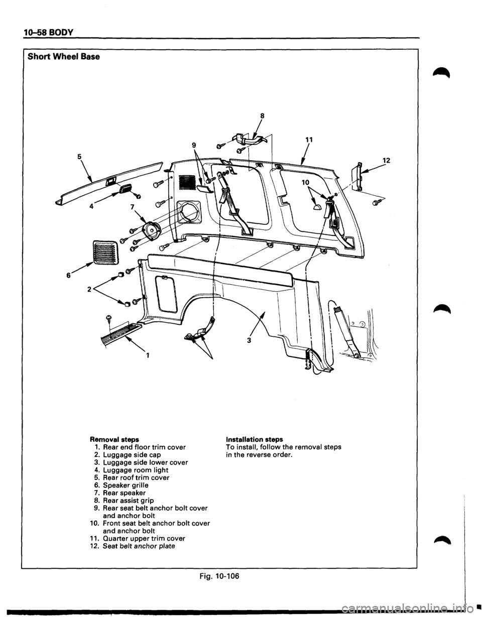
10-58 BODY
Short Wheel Base
Removal steps 1. Rear end floor trim cover 2. Luggage side cap 3. Luggage side lower cover 4. Luggage room light 5. Rear roof trim cover 6. Speaker grille
7. Rear speaker 8. Rear assist grip 9. Rear seat belt anchor bolt cover
and anchor bolt 10. Front seat belt anchor bolt cover
and anchor bolt 11. Quarter upper trim cover 12. Seat belt anchor plate
Installation steps To install, follow the removal steps
in the reverse order.
Fig. 10-106
•