diagram ISUZU TROOPER 1995 Manual PDF
[x] Cancel search | Manufacturer: ISUZU, Model Year: 1995, Model line: TROOPER, Model: ISUZU TROOPER 1995Pages: 1928
Page 1566 of 1928
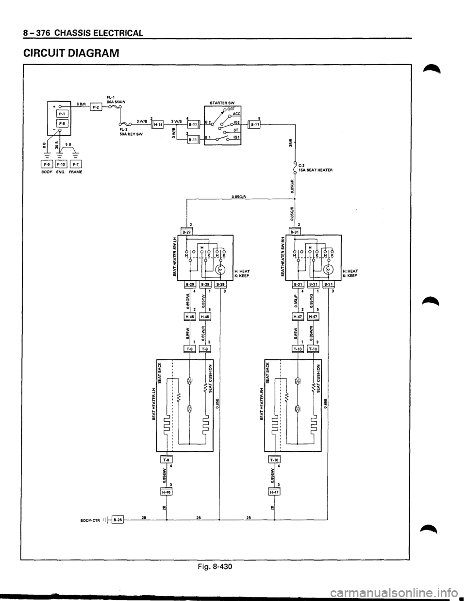
8-376 CHASSIS ELECTRICAL
CIRCUIT DIAGRAM
+ o---i--.!8'-!B~/R-'---j
~~P-1ojEj C-2 BODY ENG. FRAME 15A SEAT HEATER
O.BSG/R
BODY-CTR II B-26 1----'2"'8------------"2"-8--~._ ___ __,2-"8---~.._ _______ __,
Fig. 8-430
•
Page 1574 of 1928
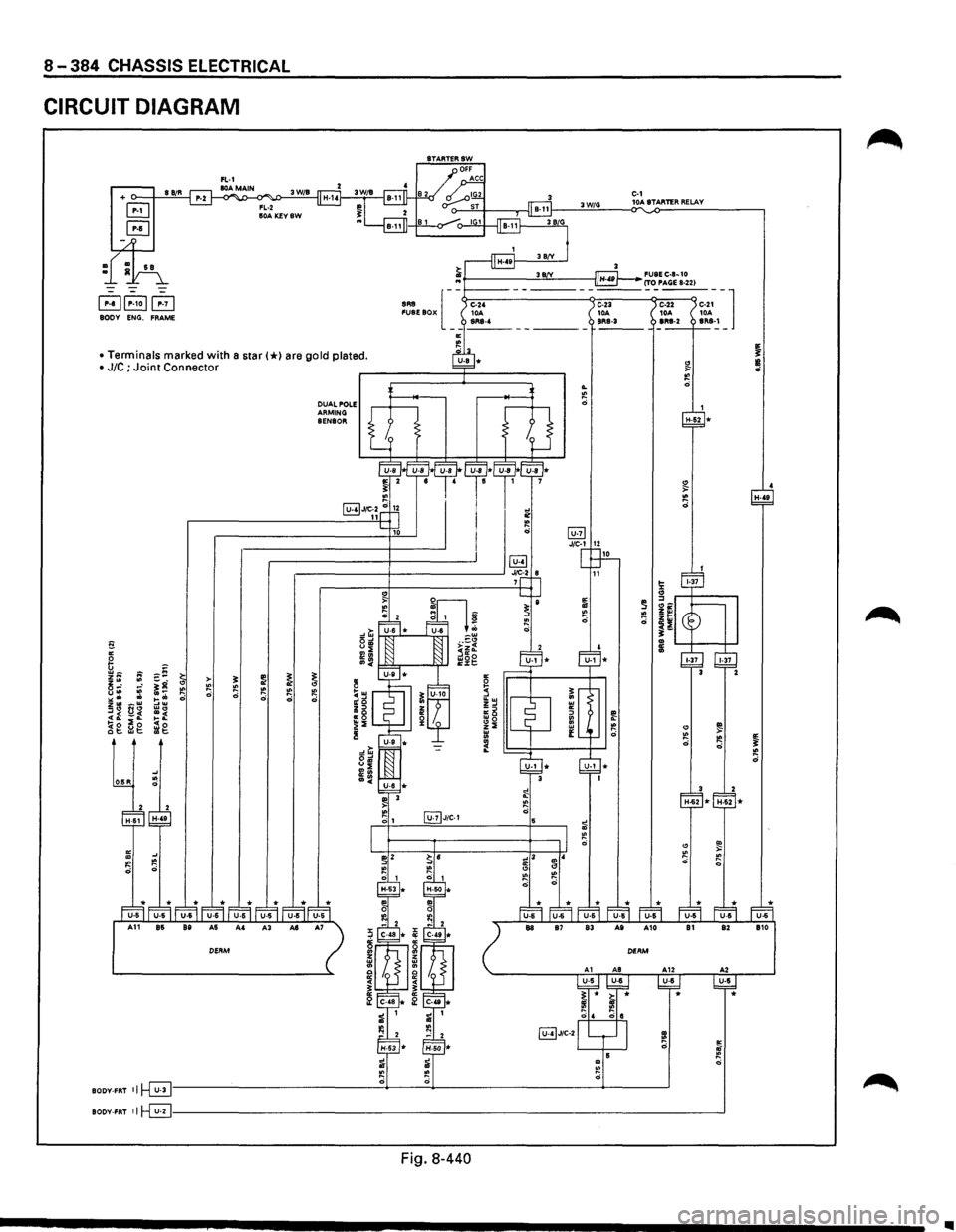
8-384 CHASSIS ELECTRICAL
CIRCUIT DIAGRAM
BODY ENG. FRAME
• Terminals marked with a star(*) are gold plated.
• J/C ; Joint Connector
fi "' 6 ;:-~ ~t; ~ >-t;: ~g " "' u"' ::: .. -~ 0 ,. .. ~: zw _w
"" 0" w., .. t. i:: =:: !(o frl@. ~g cl;
0.15R
~ ~ :e 0
0 ~
~
DUAL POLE ARMING SENSOR
~ " ~
@2)JtC·1
~J/C-2
3W/G
.. "' 0
ID "' 0
C-1 10A STARTER RELAY
BODY-FRT ~~~----------------------------------~~----~----------------------------~--------~
BODY-FRT 11~------------------------------------------------------------------------------------------__J
Fig. 8-440
H-..
•
Page 1577 of 1928
RADIO 9A-1
ACCESSORIES
Radio .................................................. .
Parts Location ..............................•...........
Circuit Diagram ......•.................................
Antenna ....•......................................•........
Auto Antenna ......................................... .
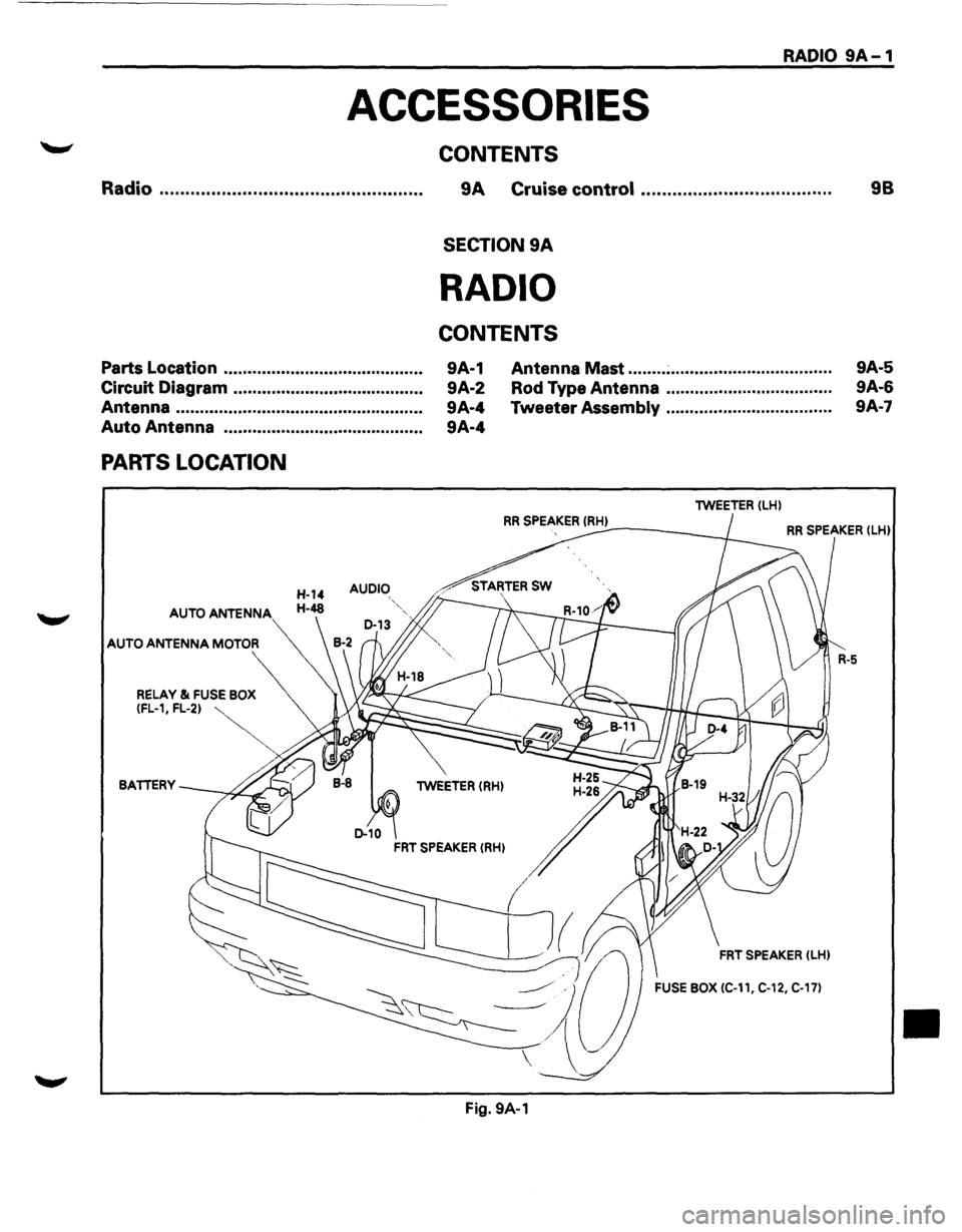
PARTS LOCATION
AUDIO
AUTO ANTENNA
AUTO ANTENNA MOTOR
CONTENTS
9A Cruise control ................................... ..
SECTION 9A
RADIO
CONTENTS
9A-1
9A-2
9A-4
9A-4 Antenna
Mast ........ ~ ................................. .
Rod Type Antenna .................................. .
Tweeter
Assembly .................................. .
lWEETER (LH)
98
9A-5
9A-6
9A·7
RR SPEAKER !RH) ----~ RR SPEAKER (lHl
BATTERY lWEETER (RH)
FRT SPEAKER (LHl
FUSE BOX (C-11, C-12, C-17)
Fig. 9A-1
•
Page 1578 of 1928
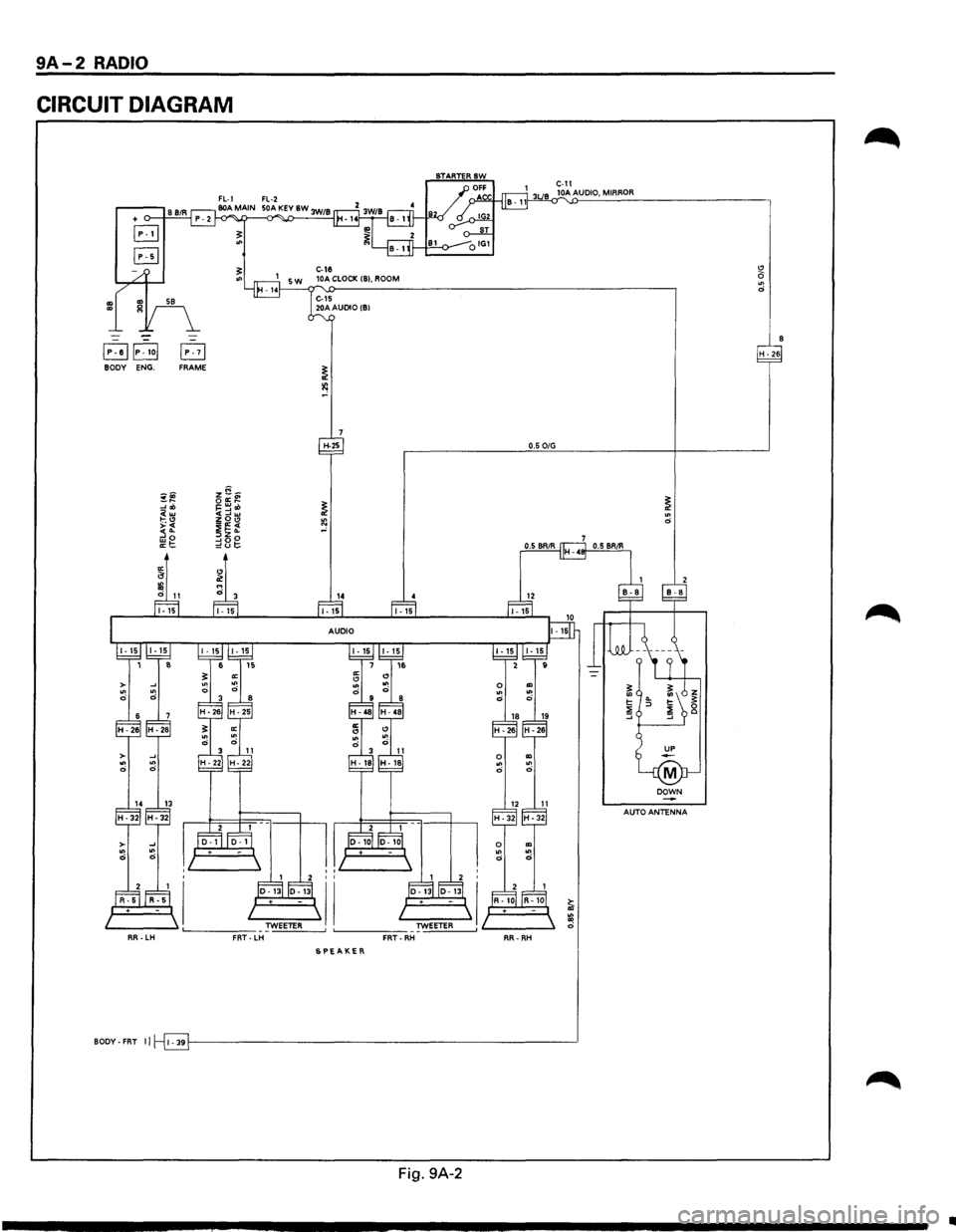
9A-2 RADIO
CIRCUIT DIAGRAM
~~P~1o[ B H · 26 BODY ENG. FRAME
H-25 0.5 0/G
~~ ~~~ ~ ~ :!ob ~==~«> <(w
SPEAKER
BODY-FAT II l-39r------------------------------------------------------------"
Fig. 9A-2
..
Page 1585 of 1928
---------------~-~---
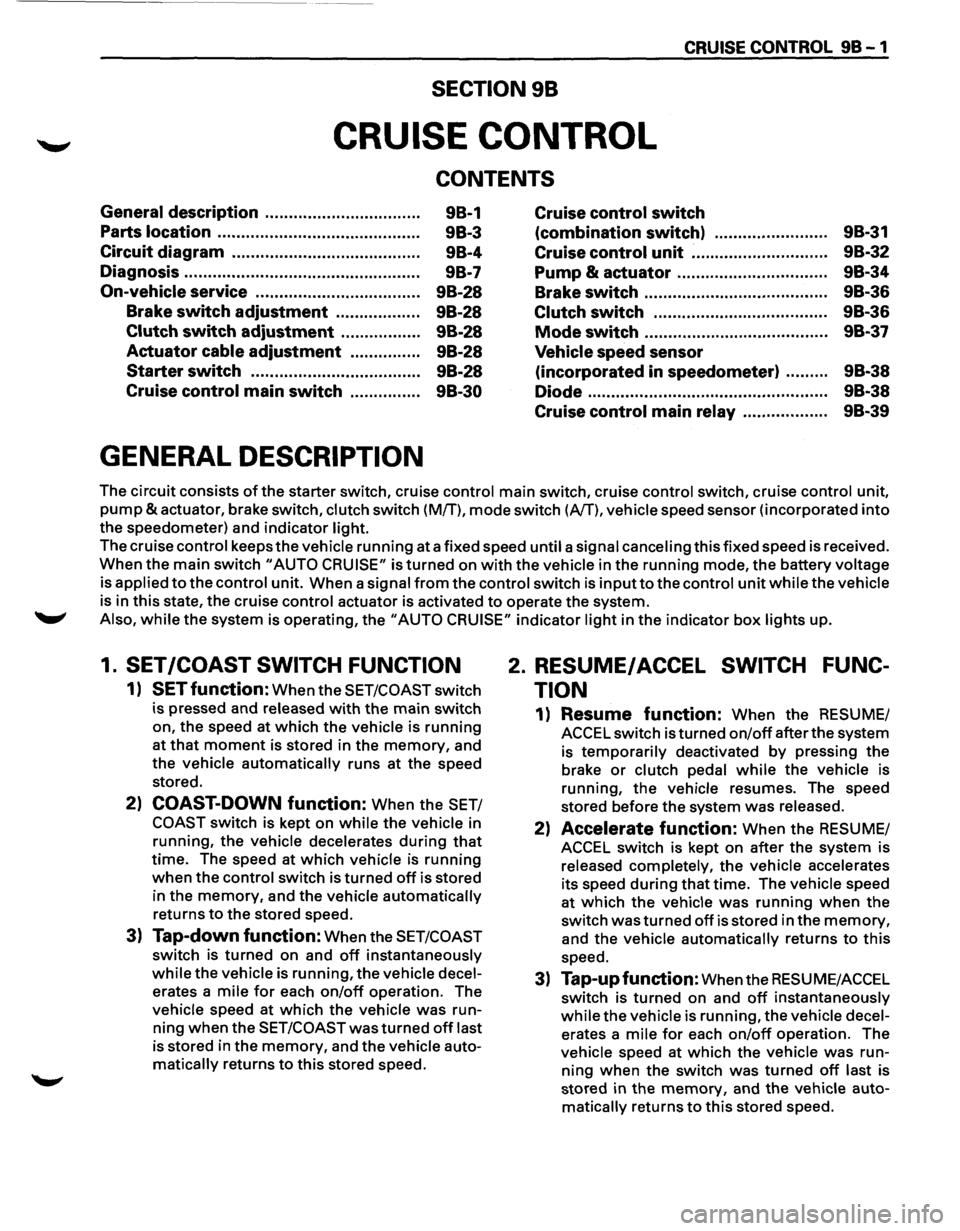
CRUISE CONTROL 9B-1
SECTION 98
CRUISE CONTROL
CONTENTS
General description ................................ .
Parts location .......................................... .
Circuit diagram ....................................... .
Diagnosis ................................................. .
On-vehicle service ................................. ..
Brake switch adjustment ................ ..
Clutch switch adjustment ................ .
Actuator
cable adjustment .............. .
Starter switch ................................... .
Cruise control main switch .............. .
GENERAL DESCRIPTION
98-1
9B-3
98-4
9B-7
98-28
9B-28
9B-28
9B-28
9B-28
9B-30 Cruise
control
switch
(combination switch) ........................ 98-31
Cruise control unit .......................... ... 9B-32
Pump
& actuator .................. .............. 9B-34
Brake switch ....................................... 9B-36
Clutch switch .............................. ....... 9B-36
Mode switch .. .. .. .. .. .. .. .. .. .. .. .. .. .. .. .. .. .. .. . 9B-37
Vehicle speed sensor
(incorporated in speedometer) ......... 9B-38
Diode
.. .. .. .. .. .. . .. .. .. .. .. . .. .. .. .. .. .. .. .. .. .. . .. .. .. 9B-38
Cruise control main relay .................. 9B-39
The circuit consists of the starter switch, cruise control main switch, cruise control switch, cruise control unit,
pump &actuator, brake switch, clutch switch (M/T), mode switch (A/T), vehicle speed sensor (incorporated into
the speedometer) and indicator light.
The cruise control keeps
the vehicle running at a fixed speed until a signal canceling this fixed speed is received.
When the main switch "AUTO CRUISE" is turned on with the vehicle in the running mode, the battery voltage
is applied
to the control unit. When a signal from the control switch is input to the control unit while the vehicle
is in this state, the cruise control actuator is activated to operate the system .
.._, Also, while the system is operating, the "AUTO CRUISE" indicator light in the indicator box lights up.
1. SET /COAST SWITCH FUNCTION
1) SET function: When the SET/COAST switch
is pressed and released
with the main switch
on, the speed at
which the vehicle is running
at that moment is stored in the memory, and
the vehicle
automatically runs at the speed
stored.
2) COAST-DOWN function: When the SET/
COAST switch is kept on while the vehicle in
running, the vehicle decelerates
during that
time. The speed at which vehicle is running
when the control switch is turned off is stored
in the
memory, and the vehicle automatically
returns
to the stored speed.
3) Tap-down function: When the SET/COAST
switch is turned on and off instantaneously
while the vehicle is running, the vehicle decel
erates a mile for each on/off operation. The
vehicle speed at
which the vehicle was run
ning when the SET/COAST was turned off last
is stored in the
memory, and the vehicle auto
matically returns to this stored speed.
2. RESUME/ ACCEL SWITCH FUNC
TION
1) Resume function: When the RESUME/
ACCEL switch is turned
on/off after the system
is
temporarily deactivated by pressing the
brake or clutch pedal while the vehicle is
running,
the vehicle resumes. The speed
stored before the system
was released.
2) Accelerate function: When the RESUME/
ACCEL switch is kept on after the system is
released completely, the vehicle accelerates
its speed
during that time. The vehicle speed
at
which the vehicle was running when the
switch
was turned off is stored in the memory,
and the vehicle automatically returns to this
speed.
3) Tap-up function: When the RESU ME/ACCEL
switch is
turned on and off instantaneously
while the vehicle is running, the vehicle decel
erates a mile for each on/off operation. The
vehicle speed at
which the vehicle was run
ning when the switch was turned off last is
stored in the
memory, and the vehicle auto
matically returns to this stored speed.
Page 1619 of 1928
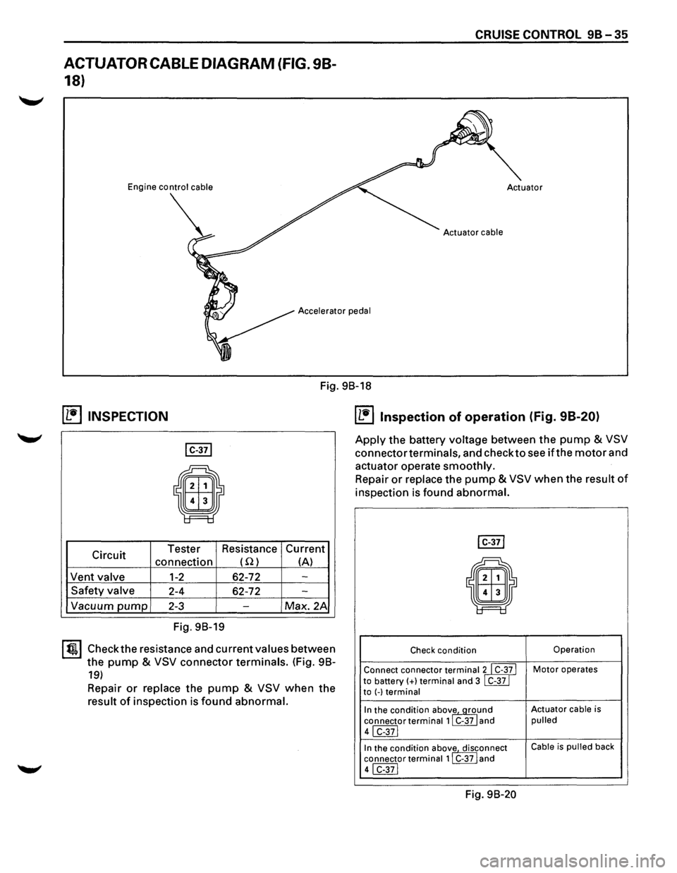
ACTUATOR CABLE DIAGRAM (FIG. 98-
18)
Engine control cable
CRUISE CONTROL 9B-35
Accelerator pedal
Fig. 98-18
~ INSPECTION
I C-371
E9
Circuit Tester
Resistance Current
connection (Q) (A)
Vent
valve 1-2 62-72 -
Safety valve 2-4 62-72 -
Vacuum pump 2-3 -Max. 2A
Fig. 98-19
I~~ Check the resistance and current values between
the
pump & VSV connector terminals. (Fig. 98-
19)
Repair or replace the pump & VSV when the
result of inspection is found abnormal.
IL1i'llnspection of operation (Fig. 98-20)
Apply the battery voltage between the pump & VSV
connector terminals, and check to see if the motor and
actuator operate
smoothly.
Repair or replace the pump & VSV when the result of
inspection is found abnormal.
I C-371
il
Check condition Operation
Connect connector
terminalll C-3~ I Motor operates
to battery(+} terminal and 3 C-37 to (-)terminal
In the condition abov~und Actuator cable is
connector
terminal 1 C-37 and pulled
41 C-371
In the condition abov
1e. disrnnect Cable is pulled back
connector
terminal 1 C-37 and
41 C-371
Fig. 98-20
Page 1654 of 1928
9J-30 Supplemental Restraint System (SRS)
HOW TO USE THIS SECTION
DIAGNOSTIC PROCEDURES
WARNING: TO AVOID DEPLOYMENT WHEN
TROUBLESHOOTING THE SRS, DO NOT USE
ELECTRICAL TEST EQUIPMENT SUCH AS A
BATTERY-POWERED OR AC-POWERED
VOLTMETER, OHMMETR,ETC. ,OR ANY TYPE OF
ELECTRICAL EQUIPMENT OTHER THAN THAT
SPECIFIED IN THIS MANUAL. DO NOT USE A
NON-POWERED PROBE TYPE TESTER.
INSTRUCTIONS IN THIS MANUAL MUST BE
FOLLOWED CAREFULLY, OTHERWISE PERSONAL
INJURY
MAY RESULT.
The diagnostic procedures used in this section are
designed to aid
in finding and repairing SRS problems.
Outlined below
are the steps to find and repair SRS
problems quickly
and effectively. Failure to carefully
follow these procedures may result in extended
diagnostic time, incorrect diagnosis and incorrect parts
replacement.
1. Perform the "SRS Diagnostic System Check". The
"SRS Diagnostic System Check" should always be
the starting point of any SRS diagnostics. The "SRS
Diagnostic System Check" checks for proper "AIR
BAG" indicator operation and checks for SRS trouble
codes using both "Flash Code" and "Scan Tool"
Methods.
2. Refer to the proper diagnostic chart as directed by
the
"SRS Diagnostic System Check". The "SRS
Diagnostic System Check" will lead you to the correct
chart to diagnose any
SRS problems. Bypassing
these procedures may
result in extended diagnostic
time, incorrect diagnosis and incorrect parts
replacement.
3. Repeat the "SRS Diagnostic System Check" after
any repair
or diagnostic procedures have been
performed.Performing the
"SRS Diagnostic System
Check" after all repair or diagnostic procedures will
assure that the repair has been made correctly and
that no other conditions exist.
DIAGNOSTIC CODES
The Diagnostic Energy Reserve Module (DERM)
maintains a history record of all diagnostic codes that
have been detected since the
SRS codes were last
cleared
during service.
1. Current Codes -Faults that are presently detected
this ignition
cycle. Active and Cycle codes are stored
in RAM (Random Access Memory).
2. History
Codes-All faults detected since the last time
the history
fault memory was cleared. History codes
are stored in EEPROM (Electrically Erasable
Programmable Read Only Memory )
HOW TO READ TROUBLE CODES
All codes (Active cycle and history) can be read (or
cleared) by using a Scan Tool (Portable Diagnostic Tool
[PDT)) or equivalent. If a PDT is not available, have the
vehicle serviced by a Saturn Dealer.
HOW TO CLEAR TROUBLE CODES
Trouble codes can only be cleared by using a Scan Tool.
If
a "Scan Tool" is not available, then inform the owner of
the stored codes and suggest that the codes are
cleared
upon the next visit to a ISUZU dealership.
SCAN TOOL DIAGNOSTICS
A Scan Tool can be used to read current and history
codes and to
clear all history codes after a repair is
complete. The scan tool must be updated to
communicate with the
SRS through a replaceable
cartridge or a manufacturer's update before it can be
used for
SRS diagnostics. To use the scan tool, connect
it to the ALDL connector and turn the ignition switch
"ON". Then follow the manufacturer's directions for
communication with the
SRS. The scan tool reads serial
data from the DERM "Serial Data" output (terminal A 11)
to the ALDL connector (terminal M) Via ISUZU
Convertible Connector (terminal 2).
BASIC KNOWLEDGE REQUIRED
Before using this section of the Service Manual, there is
some basic
knowledge which will be required. Without
this knowledge, you
will have trouble using the diagnostic
procedures
in this section. Use care to prevent harm or
unwanted
deployment. Read all cautions in the service
manual and on warning labels attached to SRS
components.
BASIC ELECTRICAL CIRCUITS
You should understand the basic theory of electricity
including series and parallel circuits, and understand the
voltage drops across series resistors. You should know
the meaning of
voltage (volts), current (amps), and
resistance (ohms). You should understand what
happens in a circuit with an open or a shorted wire. You
should be able to read and understand a wiring diagram.
"FLASH CODE" DIAGNOSTICS
"Flash Code" diagnostics are not implemented for SRS
diagnostic on TROOPER(UX)Vehicles.
Page 1893 of 1928
BODY 1Q-135
KEY
KEY CODING
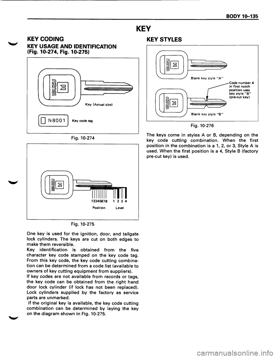
KEY USAGE AND IDENTIFICATION
(Fig. 10-274, Fig. 10-275)
I
Key (Actual size)
( 0 N8001) Keycodetag
Fig. 10-274
12345678 1 2 3 4
Position Level
Fig. 10-275
One
key is used for the ignition, door, and tailgate
lock cylinders.
The keys are cut on both edges to
make them reversible.
Key identification is obtained from the five
character key code stamped on
the key code tag.
From
this key code, the key code cutting combina
tion can be determined from a code list (available to
owners of key cutting equipment from suppliers).
If key codes are not available from records or tags,
the key code can be obtained
from the right hand
door lock cylinder (if lock has not been replaced).
Lock cylinders supplied by the factory as service
parts are unmarked.
If the original key is available, the key code cutting
combination can be determined by laying the key
on the diagram
shown in Fig. 10-275.
KEY STYLES
Blank key style "A"
Blank key style "B"
Fig. 10-276
Code number 4
in first notch position uses key style "B" (pre-cut key)
The keys come in styles A or 8, depending on the
key code cutting combination. When the
first
position in the combination is a 1, 2, or 3, Style A is
used. When the
first position is a 4, Style 8 (factory
pre-cut key) is used.
Page 1913 of 1928

CONTENTS
APPENDIX B-1
PAGE
Park ........................................................................\
....... B-3
Reverse . .")
APPENDIX B
HYDRAULIC CIRCUIT DIAGRAM
(Automatic Transmission)
CONTENTS
APPENDIX B-1
PAGE
Park ........................................................................\
....... B-3
Reverse . . . . . . . . . . . . . . . . . . . . . . . . . . . . . . . . . . . . . . . . . . . . . . . . . . . . . . . . . . . . . . . . . . . . . . . . . . .
B-5
Neutral . . . . . . . . . . . . . . . . . . . . . . . . . . . . . . . . . . . . . . . . . . . . . . . . . . . . . . . . . . . . . . . . . . . . . . . . . . . . B-6
Drive -Fourth Gear (Converter Clutch Applied} . . . . . . . . . . . . . . . . . . . . . . . . . . . . . . . . . . . . . . . B-6
Drive -Third Gear (Converter Clutch Applied} . . . . . . . . . . . . . . . . . . . . . . . . . . . . . . . . . . . . . . . . B-1
Drive -Third Gear (Converter Clutch Released} . . . . . . . . . . . . . . . . . . . . . . . . . . . . . . . . . . . . . . . B-8
Drive -Second Gear . . . . . . . . . . . . . . . . . . . . . . . . . . . . . . . . . . . . . . . . . . . . . . . . . . . . . . . . . . . . . . . . B-9
Drive -First Gear . . . . . . . . . . . . . . . . . . . . . . . . . . . . . . . . . . . . . . . . . . . . . . . . . . . . . . . . . . . . . . . . . . . B-1 0
3rd -Third Gear (Converter Clutch Released} . . . . . . . . . . . . . . . . . . . . . . . . . . . . . . . . . . . . . . . . . B-11
2nd -Second Gear . . . . . . . . . . . . . . . . . . . . . . . . . . . . . . . . . . . . . . . . . . . . . . . . . . . . . . . . . . . . . . . . . B-12
1st -First Gear . . . . . . . . . . . . . . . . . . . . . . . . . . . . . . . . . . . . . . . . . . . . . . . . . . . . . . . . . . . . . . . . . . . . . B-13