diagram ISUZU TROOPER 1995 Workshop Manual
[x] Cancel search | Manufacturer: ISUZU, Model Year: 1995, Model line: TROOPER, Model: ISUZU TROOPER 1995Pages: 1928
Page 3 of 1928
•:1
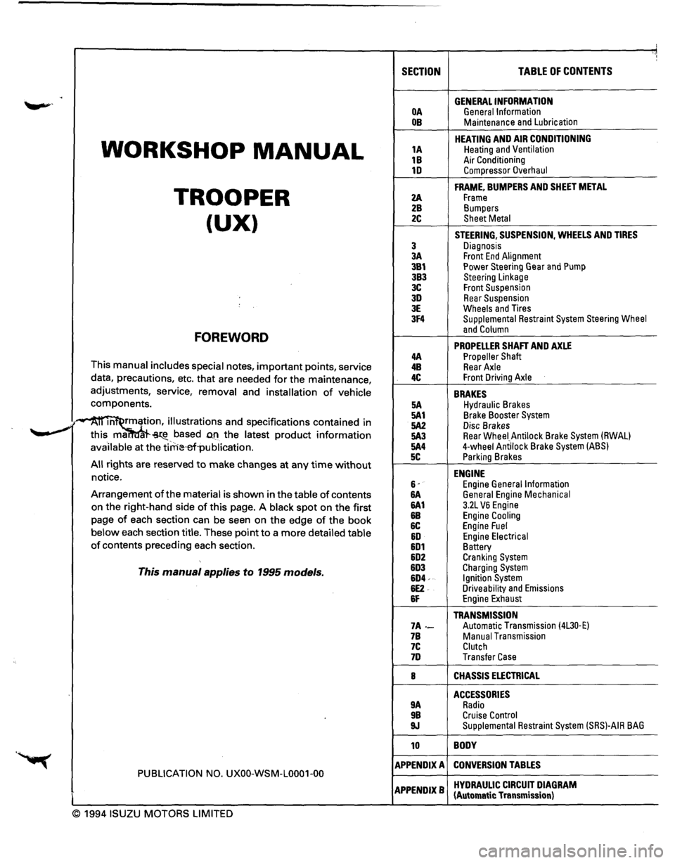
SECTION TABLE OF CONTENTS
. GENERAL INFORMATION OA General Information OB Maintenance and Lubrication
WORKSHOP MANUAL
HEATING AND AIR CONDITIONING 1A Heating and Ventilation
1B Air Conditioning 1D Compressor Overhaul
TROOPER
FRAME, BUMPERS AND SHEET METAL
2A Frame 2B Bumpers
(UX) 2C Sheet Metal
STEERING, SUSPENSION, WHEELS AND TIRES
3 Diagnosis 3A Front End Alignment 3B1 Power Steering Gear and Pump 3B3 Steering Linkage 3C Front Suspension 3D Rear Suspension 3E Wheels and Tires 3F4 Supplemental Restraint System Steering Wheel
FOREWORD and Column
PROPELLER SHAFT AND AXLE 4A Propeller Shaft This manual includes special notes, important points, service 4B Rear Axle
data, precautions, etc. that are needed for the maintenance, 4C Front Driving Axle
adjustments, service, removal and installation of vehicle BRAKES components. 5A Hydraulic Brakes
·~ m rmation, illustrations and specifications contained in 5A1 Brake Booster System
.. _,. 5A2 Disc Brakes ~ this ma. ~-based D.fl the latest product information 5A3 Rear Wheei_Antilock Brake System (RWAL)
available at the tirrHHrl·publication. 5A4 4-wheel Antilock Brake System (ABS)
5C Parking Brakes All rights are reserved to make changes at any time without ENGINE notice. 6· Engine General Information Arrangement of the material is shown in the table of contents &A General Engine Mechanical
on the right-hand side of this page. A black spot on the first 6A1 3.2L VB Engine
page of each section can be seen on the edge of the book &B Engine Cooling
6C Engine Fuel below each section title. These point to a more detailed table &D Engine Electrical of contents preceding each section. 6D1 Battery 6D2 Cranking System
This manual applies to 1995 models. 6D3 Charging System 6D4-Ignition System 6E2. Driveability and Emissions 6F Engine Exhaust
TRANSMISSION 7A-Automatic Transmission (4L30·E) 7B Manual Transmission 7C Clutch 7D Transfer Case
8 CHASSIS ELECTRICAL
ACCESSORIES 9A Radio 9B Cruise Control 9J Supplemental Restraint System (SRS)-AIR BAG
10 BODY
APPENDIX A CONVERSION TABLES PUBLICATION NO. UXOO-WSM-L0001-00
APPENDIXB HYDRAULIC CIRCUIT DIAGRAM (Automatic Transmission)
© 1994 ISUZU MOTORS LIMITED
Page 31 of 1928
HEATING AND VENTILATION 1A-1
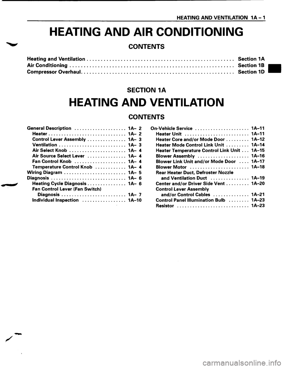
HEATING AND AIR CONDITIONING
CONTENTS
Heating and Ventilation .................................................... Section 1A
Air Conditioning . . . . . . . . . . . . . . . . . . . . . . . . . . . . . . . . . . . . . . . . . . . . . . . . . . . . . . . . . . Section 1 B
Compressor Overhaul. . .
. . . . . . . . . . . . . . . . . . . . . . . . . . . . . . . . . . . . . . . . . . . . . . . . . . . Section 1 D
SECTION 1A
HEATING AND VENTILATION
CONTENTS
General Description .................... 1A-2 On-Vehicle Service ..................... 1A-11
Heater . . . . . . . . . . . . . . . . . . . . . . . . . . . . . . 1
A-2 Heater Unit . . . . . . . . . . . . . . . . . . . . . . . . . 1A-11
Control Lever Assembly . . . . . . . . . . . . . . . 1 A-3 Heater Core and/or Mode Door ......... 1A-12
Ventilation .......................... 1A-3 Heater Mode Control Link Unit ......... 1A-14
Air Select Knob . . . . . . . . . . . . . . . . . . . . . . 1 A-4 Heater Temperature Control Link Unit ... 1A-15
Air Source Select Lever ............... 1A-4 Blower Assembly .................... 1A-16
Fan Control Knob .................... 1A-4 Blower Link Unit and/or Mode Door . . . . 1A-17
Temperature Control Knob ............ 1A-4 Blower Motor ....................... 1A-18
Wiring Diagram . . . . . . . . . . . . . . . . . . . . . . . . 1A-5
Rear Heater Duct, Defroster Nozzle
Diagnosis ............................. 1A-6 and Ventilation Duct ............... 1A-19
.. # Heating Cycle Diagnosis ............... 1A-6 Center and/or Driver Side Vent ......... 1A-20
Fan Control Lever (Fan Switch) Control Lever Assembly
Diagnosis . . . . . . . . . . . . . . . . . . . . . . . . . 1 A-7 and/or Control Cables .............. 1A-21
Individual Inspection ................. 1A-10 Control Panel Illumination Bulb ........ 1A-23
Resistor ............................ 1A-23
Page 35 of 1928
~~[II] BODY ENG. FRAME
HEATING AND VENTILATION 1A-5
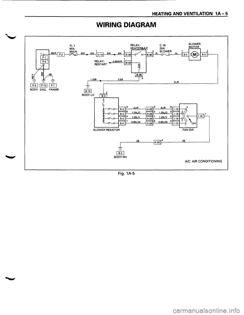
WIRING DIAGRAM
aw
RELAY;
RESTART
1.258
I 8-1el BODY-LH
0.58 2LJ8
BLOWER RESISTOR
r------'2::.::8:,__ __ _,H-201~4 ____ __,2""8 _____ __,
~ BODY-RH
AJC: AIR CONDITIONING
Fig. 1A-5
Page 55 of 1928
AIR CONDITIONING 1 B - 1
SECTION 18
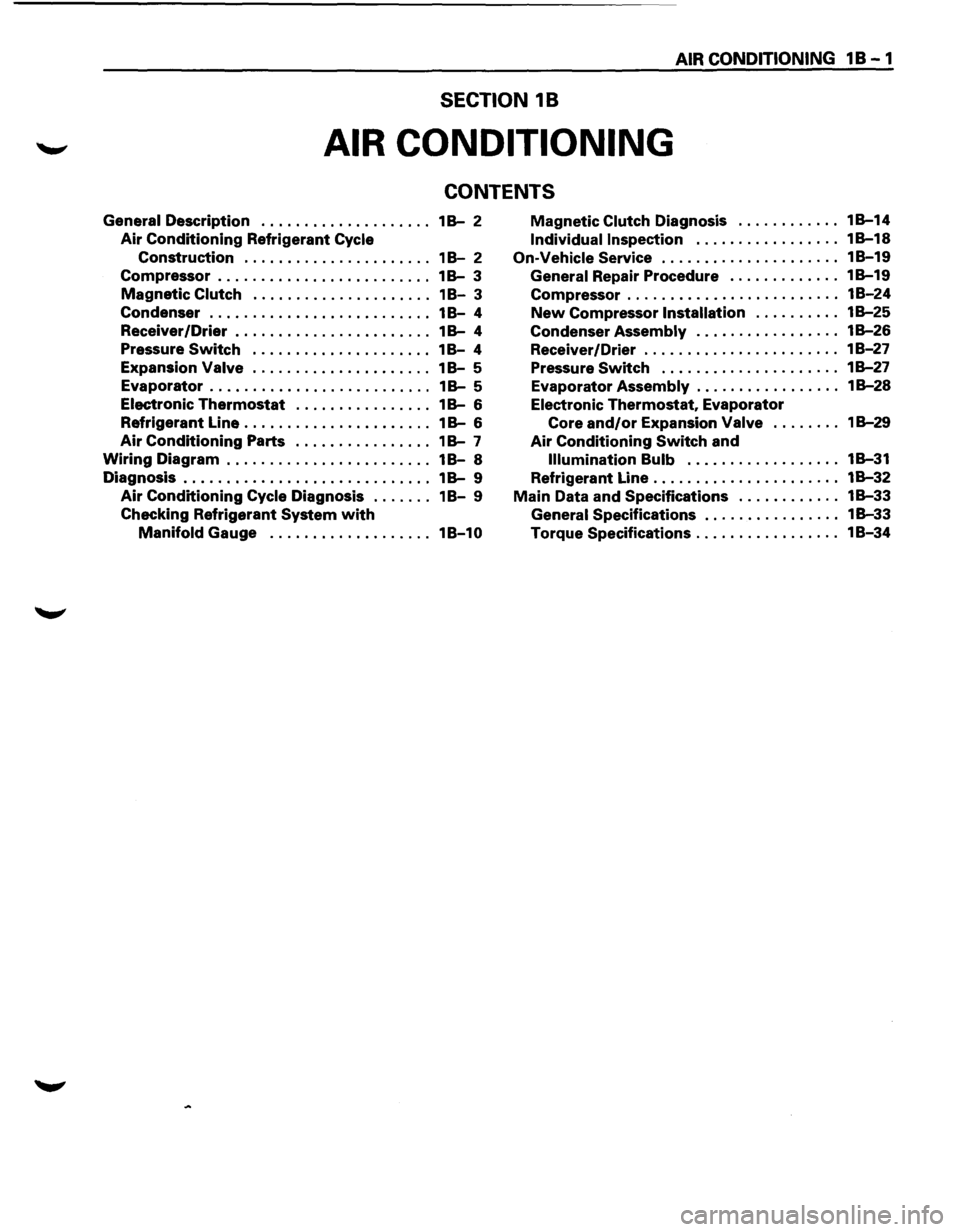
AIR CONDITIONING
CONTENTS
General Description . . . . . . . . . . . . . . . . . . . . 1 B-2
Air Conditioning Refrigerant Cycle
Construction . . . . . . . . . . . . . . . . . . . . . . 1 8-2
Compressor . . . . . . . . . . . . . . . . . . . . . . . . . 1
B-3
Magnetic Clutch . . . . . . . . . . . . . . . . . . . . . 1 8-3
Condenser . . . . . . . . . . . . . . . . . . . . . . . . . . 1
8-4
Receiver
/Drier . . . . . . . . . . . . . . . . . . . . . . . 1 B-4
Pressure
Switch . . . . . . . . . . . . . . . . . . . . . 1 8-4
Expansion
Valve . .
. . . . . . . . . . . . . . . . . . .
18-5
Evaporator . . . . . . . . . . . . . . . . . . . . . . . . . . 1 B-5
Electronic Thermostat . . . . . . . . . . . . . . . . 1 B-6
Refrigerant Line . . . . . . . . . . . . . . . . . . . . . . 1
B-6
Air Conditioning Parts . . . . . . . . . . . . . . . . 1 B-7
Wiring Diagram . . . . . . . . . . . . . . . . . . . . . . . . 18-8
Diagnosis . . . . . . . . . . . . . . . . . . . . . . . . . . . . . 1
B-9
Air Conditioning Cycle Diagnosis . . . . . . . 18-9
Checking Refrigerant
System with
Manifold Gauge ................... 18-10
Magnetic Clutch Diagnosis ............ 18-14
Individual Inspection ................. 18-18
On-Vehicle Service ..................... 18-19
General Repair Procedure ............. 18-19
Compressor . . . . . . . . . . . . . . . . . . . . . . . . . 18-24
New Compressor Installation . . . . . . . . . . 1 B-25
Condenser Assembly . . . . . . . . . . . . . . . . . 1 B-26
Receiver/Drier ....................... 18-27
Pressure Switch ..................... 18-27
Evaporator Assembly . . . . . . . . . . . . . . . . . 1 B-28
Electronic Thermostat, Evaporator
Core
and/or Expansion Valve ........ 18-29
Air Conditioning Switch and
Illumination Bulb . . . . . . . . . . . . . . . . . . 1 B-31
Refrigerant Line ...................... 18-32
Main Data and Specifications ............ 18-33
General Specifications . . . . . . . . . . . . . . . . 18-33
Torque Specifications ................. 18-34
Page 62 of 1928
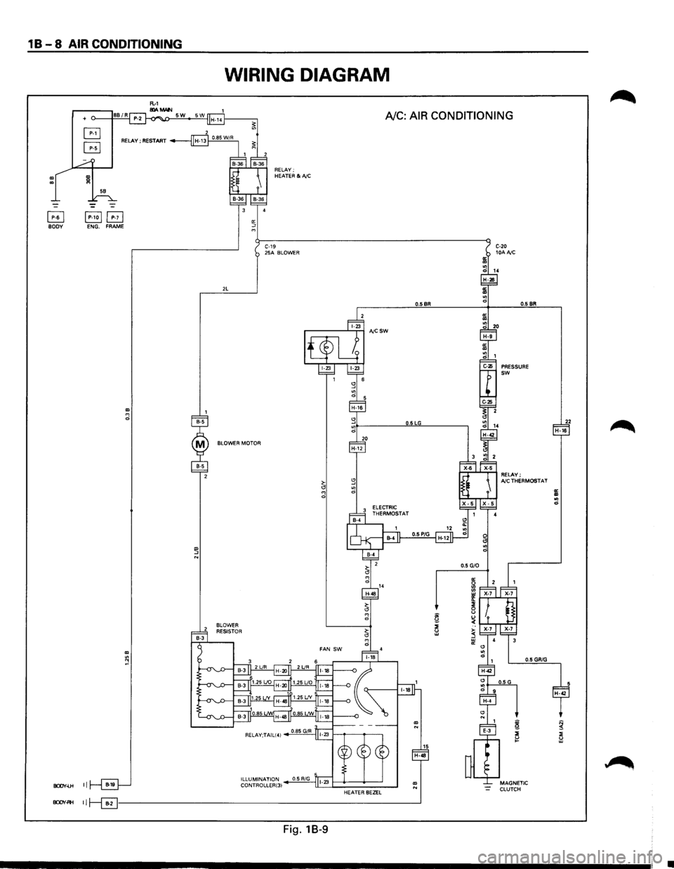
1 B - 8 AIR CONDITIONING
+
RELAY; RESTART
~ ~B BOOV ENG. FRAME
BOOV-Ui II
WIRING DIAGRAM
RELAY; HEATER &NC
A/C: AIR CONDITIONING
BOOV~ 11~--------------------------------------------------------------_j
Fig. 18-9
•
Page 369 of 1928
REAR WHEEL ANTILOCK BRAKE SYSTEM 5A3-1
SECTION 5A3
REAR WHEEL ANTILOCK BRAKE SYSTEM
(RWAL}
w CAUTION:
• All brake attaching fasteners are an important attaching part in that they could affect performance of vital
parts and systems, and/or could result in major repair expense. They must be replaced with one of the same
part
number or with an equivalent part if replacement becomes necessary. Do not use replacement parts of
lesser quality or substitute design. Torque values must be used as specified during reassembly to assure
proper retention of these parts.
CONTENTS
Introduction . . . . . . . . . . . . . . . . . . . . . . . . . 5A3· 1
General Description . .
. . . . . . . . . . . . . . .
5A3· 1
Rear
Wheel Antilock (RWAL) Control
Parts Location . .
. . . . . . . . . . . . . . . . .
5A3· 5
System Diagram . .
. . . . . . . . . . . . . . . . . . . .
5A3· 6
Rear
Wheel Antilock (RWAL) System
Diagnostics . .
. . . . . . . . . . . . . . . . . . . . . .
5A3· 7
On-Vehicle Service . .
. . . . . . . . . . . . . . . . .
5A3·38
RWAL Electronic Brake Control
Module (EBCM) Replacement ....... 5A3-38
Antilock
(Isolation/Dump) Valve
Replacement ..................... 5A3-39
Speed Sensor Replacement
.......... 5A3-40
Main Data and Specifications ........... 5A3-41
Torque Specifications
............... 5A3-41
INTRODUCTION
This section deals with the complete diagnosis and
services
for vehicles equipped with rear wheel
antilock.
For service information regarding all other
components
of the brake system, refer to "Hydraulic
Brakes"
(Sec. SA), "Brake Booster System" (Sec. SA 1)
or "Disc Brakes" (Sec. SA2) of this Manual.
GENERAL DESCRIPTION
The rear wheel anti lock system (RWAL) is designed to
reduce rear wheel lock-up during a severe brake
application,
thus maintaining rear end stability. The
system functions
by regulating the rear hydraulic
brake line pressure. The pressure regulation is
accomplished
by an anti lock valve which is located on
the
front right side of engine room. The anti lock valve
is made up of two valves, a dump valve which releases
pressure into an accumulator and an isolation valve
which maintains rear brake pressure. The valve is
controlled
by a microcomputer which is part of the
Electronic Brake Control Module (EBCM). The
EBCM is mounted at the
front of the center
console. Under severe brake application, as pressure
is
applied to the brake pedal, the EBCM is designed to
permit the valve to do one of three functions or a
combination
of all three. The EBCM will allow the valve
to either maintain the same amount of hydraulic
pressure, release hydraulic pressure through the
dump valve into the accumulator or increase the
pressure by
pulsing the isolation valve.
The EBCM operates by receiving signals from the
speed sensor (which
is located in the differential
carrier), combination
valve and the brake light switch.
The RWAL system is connected
to the RWAL indicator
light located on the dash. An indication of the RWAL
operation and a
bulb check is performed each time the
ignition is turned
"ON". The indicator light will remain
on
for about two seconds. A RWAL system
malfunction is indicated if the RWAL indicator light
stays on, or comes on during driving. To determine the
specific
trouble, refer to "RWAL System Diagnostics"
in this section.
Page 374 of 1928
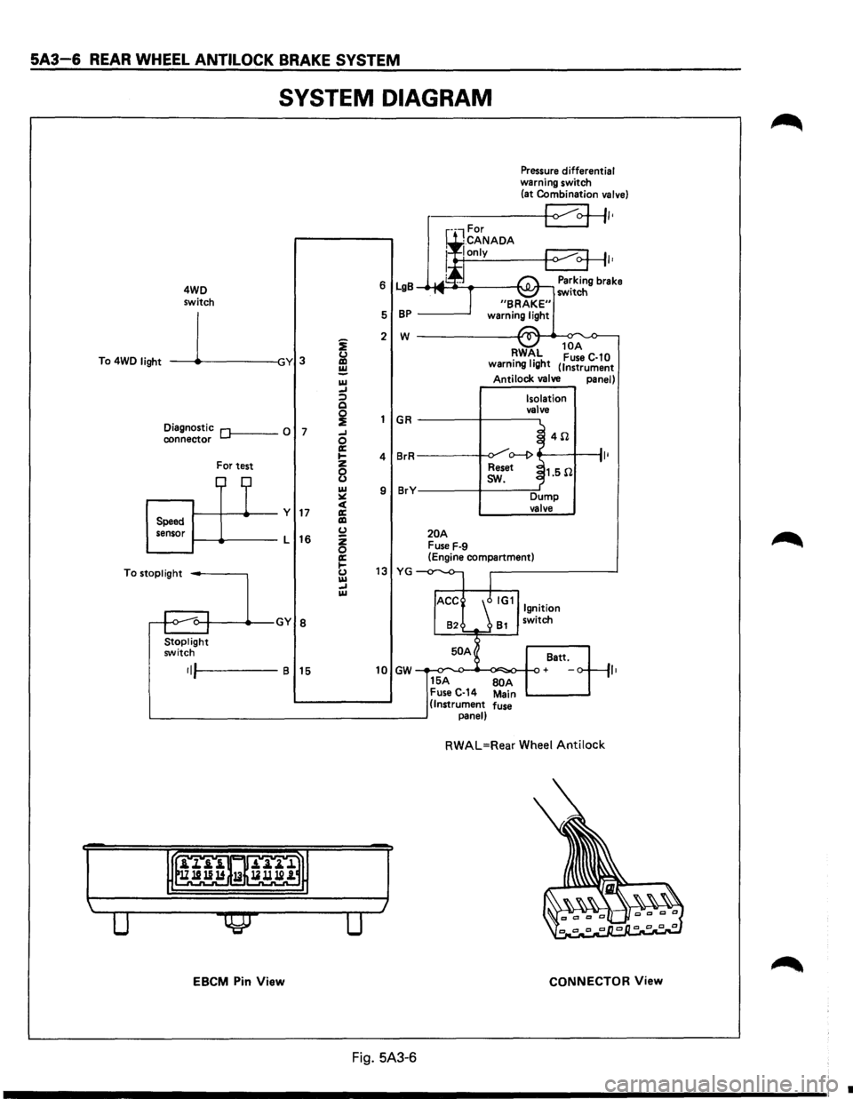
5A3-6 REAR WHEEL ANTILOCK BRAKE SYSTEM
SYSTEM DIAGRAM
4WD
switch
To 4WD
light -----11~-----lGY 3
Diagnostic Of------0 7 connector
For test
1-----11---+--y 17 Speed
sensor 1-----lt-----L
16
To
stoplight -----,
Stoplight switch
•IJI-----B 15
EBCM Pin View
i
&l ~ IU _, :;) Q
~ _, 0 a: .... z
8 IU ~ c( a: liD (.) z 0 a: 1-(.) IU _, IU
Pressure differential warning switch
(at Combination valve)
r-----+-<1 ~+II•
I•
6 LgB Parking brake _.-MI ____ ___,I'\.JI.Jr-, switch
5
BP -----'
2 w ------------~~._~
GR
4 BrR
9 BrY
20A Fuse F-9
RWAL 10
A •
1• h Fuse C-10
warnmg IQ t (Instrument
Antilock valve panel)
Isolation
valve
~ 4il .J o--1> ~
Reset ~1.5il
I
sw.
Dump valve
(Engine compartment)
13 YG -
82 81 switch
50 A
Batt.
10 GW + ,,
15A BOA Fuse C-14 Main (Instrument fuse panel)
RWAL=Rear Wheel Antilock
CONNECTOR View
Fig. 5A3-6
•
Page 411 of 1928
4-WHEEL ANTILOCK BRAKE SYSTEM (ABS) 5A4-1
SECTION 5A4
'--' 4-WHEEL ANTILOCK BRAKE SYSTEM (ABS)
CAUTION
All
brake attaching fasteners are an important attaching part in that they could affect performance of
vital parts and systems, and/or could result in major repair expense. They must be replaced with one
of the same part number or with an equivalent part if replacement becomes necessary. Do not use
replacement parts
of lesser quality or substitute design. Torque values must be used as specified
during reassembly to assure proper retention of these parts.
CONTENTS
General Description .................... 5A4-3
System Components ................. 5A4-3
Electronic Brake
Control Module ·
(EBCM) .......................... 5A4-3
Hydraulic Unit ...................... 5A4-3
ABS Warning Light .................. 5A4-4
Wheel
Speed Sensor ................. 5A4-4
G-Sensor
........................... 5A4-4
Normal and Antilock Braking .......... 5A4-4
Brake Pedal Travel
................... 5A4-4
Abbreviation ........................ 5A4-4
Diagnosis
............................. 5A4-5
General
Information ................. 5A4-5
ABS
System Service Precautions ....... 5A4-5
Computer System Service
Precautions
....................... 5A4-5
General Service Precautions
........... 5A4-5
Note on lntermittents ................ 5A4-6
Test Driving ABS Complaint Vehicles ... 5A4-6
II ABS11 Warning Light ................ 5A4-6
Normal Operation ................... 5A4-6
Basic
Diagnostic Flow Chart ........... 5A4-7
Basic
Inspection Procedure ............ 5A4-8
TECH 1
TOOL. ......................... 5A4-10
1. What can be done with TECH 1 ...... 5A4-10
2. How to Use TECH 1 ................ 5A4-11
3. Explanation of Modes .............. 5A4-15
Mode FO: Data List ................... 5A4-16
Mode F2: Trouble Code ............... 5A4-18
Mode F3: Snapshot .................. 5A4-19
Mode F4: Clear Code ................. 5A4-20
Mode F5: Actuator Test ............... 5A4-21
Mode F6: Wheel Sensors ............. 5A4-31
Pin-Out Checks ........................ 5A4-33
Circuit Diagram ..................... 5A4-34
Part Location ....................... 5A4-37
Symptom Diagnosis .................... 5A4-38
CHART A-1 1) ABS Works Frequently
but Vehicle does not Decelerate ...... 5A4-39
CHART TA-1 1) ABS Works Frequently
but Vehicle does not Decelerate ...... 5A4-40
CHART A-2 2) Uneven Braking Occurs
while ABS Works .................. 5A4-41
CHART TA-2 2) Uneven Braking Occurs
while ABS Works .................. 5A4-42
CHART A-3, T A-3 3) The Wheels are
Locked
........................... 5A4-43
CHART A-4 4) Brake Pedal Feel is
Abnormal ........................ 5A4-44
CHART A-5 , T A-5 5) Braking Sound
(from Hydraulic Unit) is Heard while
not Braking ....................... 5A4-45
Diagnosis by 11 ABS11 Warning Light
Illumination Pattern .................. 5A4-46
Diagnostic Trouble Codes (DTCs) ....... 5A4-47
1. How to Display and Erase DTCs ... 5A4-47
2. Diagnostic Trouble Codes ........ 5A4-49
CHART B-1 With the Key in the ON
Position (before Starting the Engine),
Warning Light (W /L) is not
•
Actuated ........................ 5A4-50
CHART B-2 II ABSII Light Flashes
Twice with Key ON ................ 5A4-51
CHART B-3 EBCM Abnormality (Diagnostic
Trouble Code 14) .................. 5A4-52
CHART B-4 Power Voltage Drop (Diagnostic
Trouble Code 15) .................. 5A4-53
CHART B-5 G-Sensor Circuit (Diagnostic
Trouble Code 21) .................. 5A4-54
CHART B-6 Brake Switch Trouble
(Diagnostic Trouble Code 22) ........ 5A4-55
CHART B-7 Abnormal Transmission Input
(A/T Modei)(Diagnostic Trouble
Code 23) ......................... 5A4-56
CHART B-7 Abnormal Transmission Input
(M/T Modei)(Diagnostic Trouble
Code 23) ......................... 5A4-57
CHART B-8 Hydraulic Unit (HU) Pump
Motor and Motor Relay Circuit
(Diagnostic Trouble Code 32) ........ 5A4-58
CHART B-9 Solenoid Valve Abnormality
(Diagnostic Trouble Code 41, 42,
& 44) ............................ 5A4-59
CHART B-10 Valve Relay Abnormality
(Diagnostic Trouble Code 45) ........ 5A4-60
Page 444 of 1928
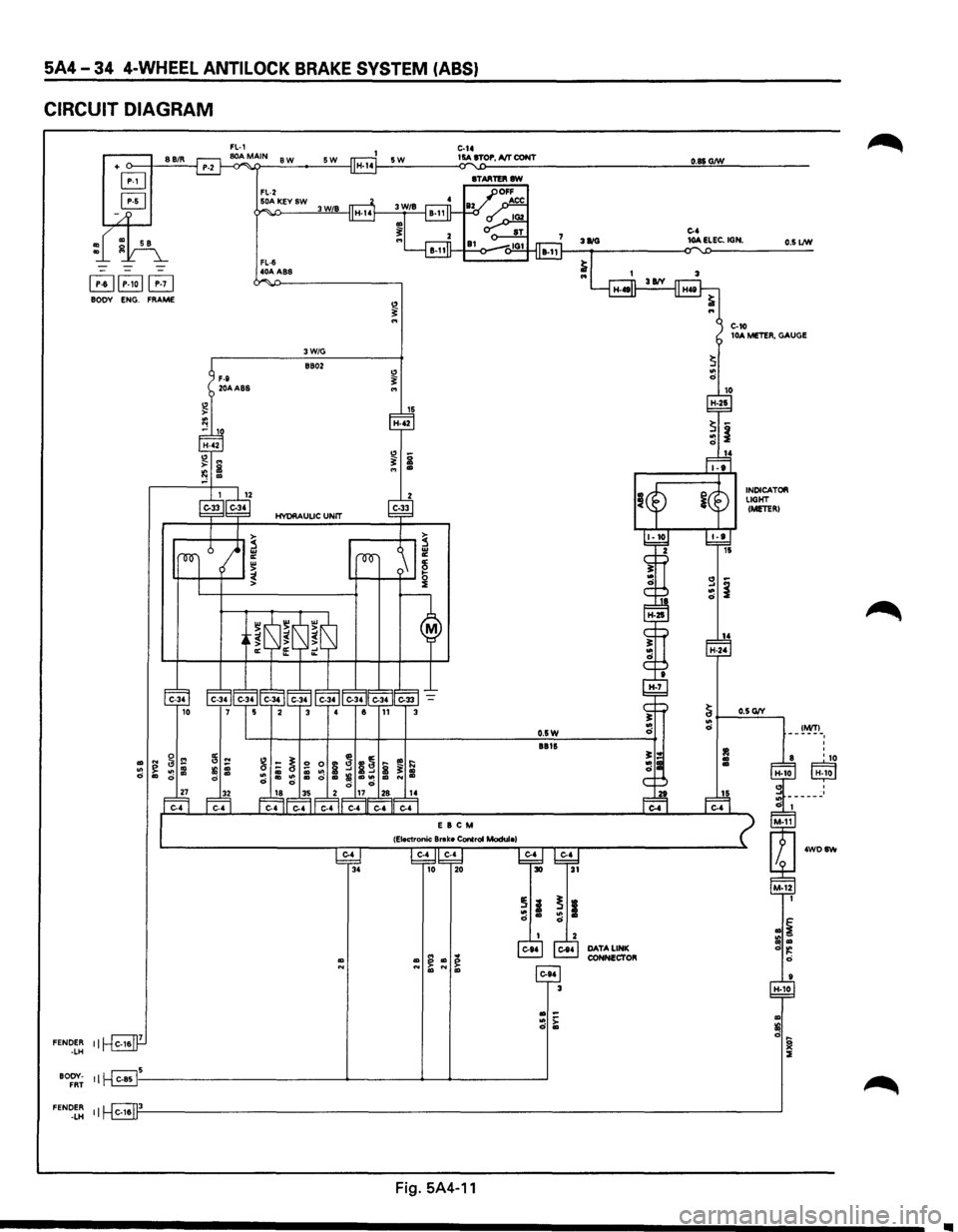
5A4-34 4-WHEEL ANTILOCK BRAKE SYSTEM (ABS)
CIRCUIT DIAGRAM
FENDER -LH
BODY· FRT
FENDER -LH
+ o-----J----'8:..:8:..:/R~
B
EJ
~~B BODY ENG. FRAME
II
11~5
II C-16
E 8 C M
Fig. 5A4-11
o.sw 8BI6
.. -d ~
DATA LINK CONNECTOR
C-4 lOA ELEC. IGN. O.Sl/W
C-10 lOA METER, GAUGE
H-24
IM/TI ------~
H-10
I I I 10
I H;lo I
4WDS1111
•
Page 697 of 1928
DRIVEABILITV AND EMISSIONS 6E2-1
SECTION 6E2
DRIVEABILITV AND EMISSION
CONTENTS
Driveability and Emission General Section B-
Information ....................... 6E2- 2 Driveability Symptoms . . . . . . . . . . . 6E2-89
Section
A-Section C-
Engine Components/Wiring Diagrams/ Component Systems . . . . . . . . . . . . . 6E2-99
Diagnostic
Charts ................. 6E2-23