diagram ISUZU TROOPER 1995 Owner's Guide
[x] Cancel search | Manufacturer: ISUZU, Model Year: 1995, Model line: TROOPER, Model: ISUZU TROOPER 1995Pages: 1928
Page 873 of 1928
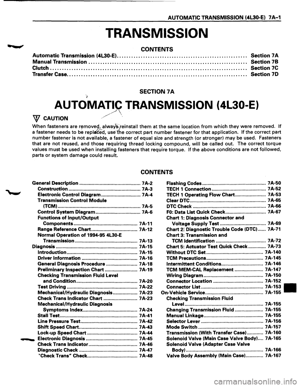
AUTOMATIC TRANSMISSION (4l30-E) 7 A-1
TRANSMISSION
CONTENTS
Automatic Transmission (4L30-E). . . . . . . . . . . . . . . . . . . . . . . . . . . . . . . . . . . . . . . . . . . . . . . . . . . . . . . Section 7 A
Manual Transmission . .
. . . . . . . . . . . . . . . . . . . . . . . . . . . . . . . . . . . . . . . . . . . . . . . . . . . . . . . . . . . . . . . . . Section
78
Clutch . . . . . . . . . . . . . . . . . . . . . . . . . . . . . . . . . . . . . . . . . . . . . . . . . . . . . . . . . . . . . . . . . . . . . . . . . . . . . . . . . . . Section 7C
Transfer Case. . . . . . . . . . . . . . . . . . . . . . . . . . . . . . . . . . . . . . . . . . . . . . . . . . . . . . . . . . . . . . . . . . . . . . . . . . . . Section 70
SECTION 7A
AUTOMAT~ TRANSMISSION (4L30-E)
/' W CAUTION ./
When fasteners are r~movec;l, alway~reinstall them at the same location from which they were removed. If
a fastener needs to be repl£ed, use1'he correct part number fastener for that application. If the correct part
number fastener is not available, a fastener of equal size and strength (or stronger) may be used. Fasteners
that are not reused, and those requiring thread locking compound, will be called out. The correct torque
values must be used when installing fasteners that require torque. If the above conditions are not followed,
parts or system damage could result.
CONTENTS
General Description ............................................. 7 A-2 Flashing Codes ............................................... 7 A-50
Construction ..................................................... 7 A-3 TECH 1 Connection ........................................ 7 A-52
Electronic Control Diagram ............................. 7A-4 TECH 1 Operating Flow Chart ....................... 7 A-53
Transmission
Control Module Clear DTC ........................................................ 7 A-65
(TCM) ............................................................. 7A-5 DTC Check ...................................................... 7 A-66
Control System Diagram ................................. 7 A-6 FO: Data List Quick Check .............................. 7A-67
Functions
of Input/Output Chart 1: Diagnosis Connector and
Components ............................................... 7A-11 Voltage Supply Test .................................. 7A-69
Range Reference
Chart .................................. 7A-12 Chart 2: Diagnostic Trouble Code (DTC) ...... 7A-71
Normal Operation of 1994-95 4L30-E Chart 3: Transmission and
Transmission .............................................. 7 A-13
TCM Identification ..................................... 7 A-72
Diagnosis ............................................................ 7A-15
Chart 5: Actuator Test Quick Check ............. 7A-73
Introduction .................................................... 7A-15 Without DTC Set .......................................... 7 A-140
Driver Information ......................................... 7 A-16 TCM Precautions .......................................... 7A-145
General Diagnosis Procedure ....................... 7A-18 Intermittent Conditions ............................... 7A-146
Preliminary Inspection Chart ........................ 7 A-19 TCM MEM-CAL Replacement ..................... 7A-147
Checking Transmission Fluid Level Wiring Diagram ............................................ 7A-150
and
Condition ............................................. 7 A-20 Connector Location
..................................... 7A-152
Test Driving .................................................... 7 A-22
Mechanical/Hydraulic Diagnosis .................. 7 A-23
Connector List .............................................. 7A-153 •
On-Vehicle
Service ........................................... 7A-155
Check Trans Indicator Chart ......................... 7 A-23 Checking Transmission Fluid
Mechanical/Hydraulic
Diagnosis Level .......................................................... 7A-155
Symptoms Index ........................................ 7A-24 Changing Transmission Fluid ..................... 7A-155
Stall Test ......................................................... 7 A-41 Manual Linkage ............................................ 7A-155
Line Pressure Test .......................................... 7 A-42
Selector Lever .............................................. 7 A-156
Shift Speed Chart ........................................... 7 A-43 Mode Switch ................................................ 7A-157
Lock-up
Speed Chart ..................................... 7 A-44 Transmission
(With Transfer Case). ........... 7A-160
....._ Electronic Diagnosis ...................................... 7 A-45 Solenoid Valve (Main Case Valve Body) .... 7A-165
Check Trans Indicator .................................... 7 A-46 Solenoid Valve (Adapter Case Valve
Diagnostic Check ........................................... 7 A-47 Body)
......................................................... 7A-166
''Check Trans" Check ..................................... 7 A-48 Valve Body Assembly (Main Case) ............. 7A-167
Page 874 of 1928
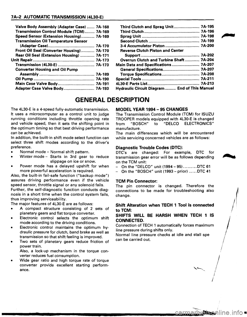
7A-2 AUTOMATIC TRANSMISSION (4L30-E)
Valve Body Assembly (Adapter Case) ....... 7A-168 Third Clutch and Sprag Unit ....................... 7A-195
Transmission Control
Module (TCM) ......... 7A-169 Third Clutch .................................................. 7A-196
Speed Sensor (Extension Housing) ............ 7A-169 Sprag
Unit ....................................................
7A-198
Transmission
Oil Temperature Sensor Second
Clutch .............................................. 7A-199
(Adapter Case) ..........................................
7A-170 3-4 Accumulator Piston ............................... 7A-200
Front Oil Seal (Converter Housing) ............ 7A-170 Reverse Clutch Piston and Center
Rear
Oil Seal (Extension Housing) ............. 7A-171 Support ..................................................... 7 A-202
Unit Repair ........................................................ 7A-173 Overrun Clutch and Turbine Shaft ............. 7A-204
Transmission (4L30-E) ................................. 7A-173 Main Data and Specifications ......................... 7 A-207
Converter Housing and Oil Pump General
Specifications ................................. 7 A-207
Assembly .................................................. 7 A-189 Torque
Specifications .................................. 7A-208
Oil
Pump ....................................................... 7A-190 Special Tools .................................................... 7A-211
Main Case Valve Body ................................. 7A-191 4L30-E Parts List.. ............................................. 7A-213
Adapter Case Valve Body ............................ 7A-193 Hydraulic
Circuit Diagram .......... End of This Manual
GENERAL DESCRIPTION
The 4L30-E is a 4-speed fully-automatic transmission.
It uses a microcomputer as a control unit to judge
running conditions
including throttle opening rate
and vehicle speed, then
it sets the shifting point in
the
optimum timing so that best driving performance
can be achieved.
In addition, the built-in shift mode select function can
select three shift modes according to the driver's
preference.
• Normal mode-Normal shift pattern.
• Winter mode-Starts in 3rd gear to reduce
slippage on ice
or snow.
• Power mode has a delayed upshift for when
more powerful acceleration is required.
Also, the built-in fail-safe
function ("backup mode")
assures driving performance even if the vehicle
speed sensor,
throttle signal or any solenoid fails.
Further, the self-diagnostic
function conducts diag
nosis in a short time when the control system fails,
thus improving serviceability.
The major features of 4L30-E are as follows:
• A compact structure consisting of 2 sets of
planetary gears and flat torque converter.
• Electronic control selects the optimum shift
mode according
to the driving conditions.
• Electronic control maintains the optimum hy
draulic pressure for clutch, band brake as well as
transmission so that shift feeling is improved.
• Two sets of planetary gears reduce friction of
power train.
Also, a lock-up mechanism in the torque con
verter reduces fuel consumption.
• Wide gear ratio and high torque rate of torque
converter provide
excellent starting perform
ance.
MODEL YEAR 1994-95 CHANGES
The Transmission Control Module (TCM) for ISUZU
TROOPER
models equipped with 4L30-E is changed
from "BOSCH" to "DELCO ELECTRONICS"
manufacture.
The main differences
which will be encountered
while servicing concerned vehicles are as follows:
Diagnostic Trouble Codes (DTC):
DTC's are changed: For example, DTC for
transmission gear error will be as follows depending
on the TCM unit:
-
On the "DELCO" unit (1994-95) ......... DTC 61
-On the "BOSCH" unit (1993-prior) ..... DTC 41
TCM Pin Connector:
The pin connector is changed. Therefore the
connections
to be made for troubleshooting also
change.
Shift Alteration when TECH 1 Tool is connected
toTCM:
SHIFTS WILL BE HARSH WHEN TECH 1 IS
CONNECTED.
Connection of TECH 1 automatically forces maximum
line pressure during shifts only.
Normal line pressure checks at idle and stall spe
can be carried out.
/
/
I J I
/
l
•
Page 878 of 1928
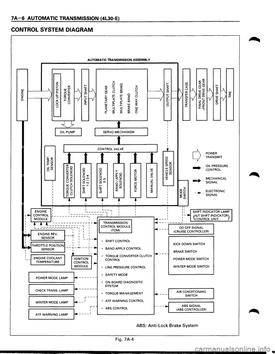
7A-6 AUTOMATIC TRANSMISSION (4L30-E)
CONTROL SYSTEM DIAGRAM
L1J ~ (!) z L1J
I
I
lr
t:··
~ .. I I
I
I
AUTOMATIC TRANSMISSION ASSEMBLY
O.:a: :Eo LLJ(J) t-z --' L1J oVl
ENGINE COOLANT TEMPERATURE
ffio ~---a:O wz >LLJ z--' oo uCJ> w::C :::>u at-a:=> ~d
0 0 z ... w, --'"' o-.. (J)N t-.!-u.. J: CJ)
IGNITION
CONTROL .
MODULE
~==PO=W==ER==M=O=D=E=L=A=M=P~r.-------
r-------CHECK TRANS. LAMP
~=W=IN=T=E=R=M=O=D=E=LA=M=P~~--J---
::c u L1J a: 1-:.:: ::c <( :::> <( u L1J --' a: 1-(!) u al :::> >-L1J L1J 0 --' 1-~ z u a: :5 <( ~ ~ --' al Cl.
Cl. L1J i=
i= L1J ~ z :.:: --' --' <( L1J :5 :::> :::> a: z Cl. ::!: ::!: al 0
0 a: L1J 0 >-0 > --'o --' z (l._ 1-<( L1J Cl.Q 0 > __,...,
SHIFT
CONTROL
BAND APPLY CONTROL
TORQUE CONVERTER CLUTCH CONTROL
LINE PRESSURE CONTROL
SAFETY MODE
ON-BOARD DIAGNOSTIC
SYSTEM
TORQUE MANAGEMENT
ATF WARNING CONTROL
r-ABS CONTROL
L--A-T_F_w_A_R_N_I_N_G_L_A_M_P_...Jr---_l 1---------------'
0 L1J "'a: Bio wVl __,z uw J:Vl L1J >
POWER c): TRANSMIT
.... : OIL PRESSURE
CONTROL
MECHANICAL
...• : SIGNAL
LLJJ: ou ELECTRONIC ot:: -•: ::!:~ SIGNAL
KICK DOWN SWITCH
BRAKE SWITCH
POWER MODE SWITCH
WINTER MODE SWITCH
AIR CONDITIONING
SWITCH
ABS
SIGNAL (ASS CONTROLLER)
ABS: Anti-Lock Brake System
Fig. 7A-4
..
Page 880 of 1928
7 A-8 AUTOMATIC TRANSMISSION (4l30-E)
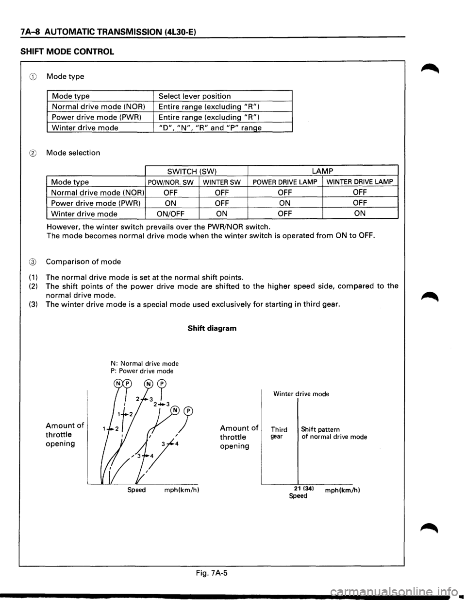
SHIFT MODE CONTROL
CD Mode type
Mode type Select lever position
Normal drive mode (NOR) Entire range (excluding "R")
Power drive mode (PWR) Entire range (excluding "R")
Winter drive mode "D", "N", "R" and "P" range
® Mode selection
SWITCH
(SW) LAMP
Mode type POW/NOR. SW WINTER SW POWER DRIVE LAMP WINTER DRIVE LAMP
Normal drive mode (NOR) OFF OFF
OFF OFF
Power drive mode (PWR) ON OFF ON OFF
Winter drive mode ON/OFF
ON OFF ON
However, the winter switch prevails over
the PWR/NOR switch.
The
mode becomes normal drive mode when the winter switch is operated from ON to OFF.
@ Comparison of mode
(1) The normal drive mode is set at the normal shift points.
(2) The shift points of the power drive mode are shifted to the higher speed side, compared to the
normal drive mode.
(3) The winter drive mode is a special mode used exclusively for starting in third gear.
Amount of
throttle
opening
N: Normal drive mode P: Power drive mode
Shift diagram
Winter drive mode
Amount of Third Shift pattern
throttle gear of normal drive mode
opening
Speed mph(km/h) 21 1341 mph(km/h) Speed
Fig. 7A-5
..
Page 917 of 1928
ELECTRONIC DIAGNOSIS
HOW TO DIAGNOSE THE PROBLEM
~ 1. To avoid incorrect diagnostics: this book needs
to be followed accurately. Unless stated: do
not jump
directly to a section that could
contain the solution: some important
information may be missed.
2. The sections in CAPITALS and bold are the
main sections that can be found in the
contents.
3. The GOTO "SECTION" means to continue to
check going to the "section".
4. The GOTHROUGH "SECTION" means to go
through the "section" and then to go back to
the place the GOTHROUGH was written.
5. BASIC ELECTRIC CIRCUITS:
You should understand the basic theory of
electricity. This will include the meaning of
voltage, amps, ohms, and what happens in a
circuit with an open or shorted wire. You
should also be able to read and understand
wiring diagrams.
6. IGNITION CYCLE:
When the car is driven a malfunction can occur
due to a car wiring harness problem, in this
case the driver can reset the system (as on a
personal computer). To reset the computer he
must: (
1) Stop the car and the engine.
(2) Turn the key ignition OFF.
(3) Turn the key ignition ON.
AUTOMATIC TRANSMISSION (4L30·E) 7 A-45
Page 1022 of 1928
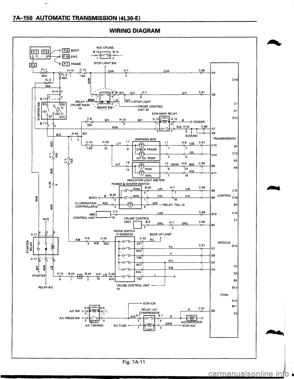
7A-150 AUTOMATIC TRANSMISSION (4L30-E)
WIRING DIAGRAM
L--<~o-~~~~~~--~~~----~~~----~~--------------~G"IW~------------C«-9_0--iA4
D16
30A
D12
GfY ---~:at--B-'li BfY G(Y H-7 ,...-..~., 4,' ~ ~
RELAY ~' ~:iO 1 [my_ STOP LIGHT
2 3 I CRUISE MAIN '..BRAKES '' L------•CRUISE CONTROL (4) - ---vy UNIT (8) D1
~2
8-11+~---f4
~ 81~ Q._ ("'~2
~ IG1 18~ ~ ST ACC en 8-11
C-91 D9
C1
ECM MAIN RELAY
X-f~ ~X~~2 8 II• FENDER R/W : - : RiG H-42 C-90 '-----t--t------+-------!:!Lll----------< • ~( r fl A7 2 4 8 L....{+--AS
C-8
~A
H-13 BfY BfY 3 7 3
L-+-JB~~I,_IG __ __....,~4-B(Y ECM(A61 1 3 WARNING BOX TRANSMISSION
~T'~5'-'1:D----H-+~2~5 LfY ~~~ ~K TRANS 1-,17 Hr7 :~ C-~1 C10 C::
0 ~
"' <( u :!?
'----~
"' ":' 0'> J:
IXl ~ a: ~
I~ A10 AJT OIL TEMP 2
8
A
2
LfY 1-9~ ~1-9 GR/W H;9 BiG C-90 89 1~ POW. : 8 ~3 , A9
- -~· PiG c(-A11 WIN. 7 19 INDICATOR LIGHT (METER) POWER & WINTER SWITCH
_,. POW. 8-30 ViR H-,>,7:;-----'V"-'iR.!..,_ ___ c<-~9-0-l B8 C15 II-v 3, :7 • BODY of~~ ~-o-WIN. 1 ,' ViG -----.+.,.,176 __ ____;;V.:..;iG=-----<+'-----1 B
6 CONTROL C16 ,4 ILLUMINATION~' ~ '~RELAY: TAIL (4) CONTROLLER(3) 2 -~ 5
ABS ~c~4----------------__yV:J..:!:!._/W ______________ ___:C<-~9:..::0-l B 10 CONTROL UNIT 16 CRUISE CONTROL
RiB H-8 C-43
4 RiB 5(D)
UNIT Q;·>-9------"G,_,Ri_,L_~:+--;-----'G""R""iL::,_ ___ c,-+-9-0----j 84
MODE SWITCH
IT-MISSION)
C-43
2(F) ~ ' 8(A), '
BACKUP LAMP
RiL
t
PiL
p
C-91 ( D7 : D6
B3
C14
C7
MODULE D14
: D5 : C5 ( D4 C6
B5
7(B)'
X-17-l-~J,-~L -v-: 6((:1§': :
r! -v-u-3tGi'', STARTER H-~..._:4---4r::J-Mo~-_B~;~;8 LJR C;~434--o-_,_-o---+---<·' L ---1 8 1 [::::J 2 15 4(H) u---~< 1 '
CRUISE CONTROL UNIT RELAY;A/C (4)
DB
(TCM) 812
A12
811
C8
....
'
Fig.7A·11 I
------------------------~~
•
Page 1023 of 1928
A4
D16
D9
C1
D1
D12
A7
AB
TRANSMISSION
A3 C10 C12
B9
A2
All A9 A10
BB C15
B6 C16
CONTROL
B3
B10 C14
C7
B4
D14
MODULE
D7 D6
D5
C5 D4 C6
B5
B12
(TCMI
A12 B11
DB
CB
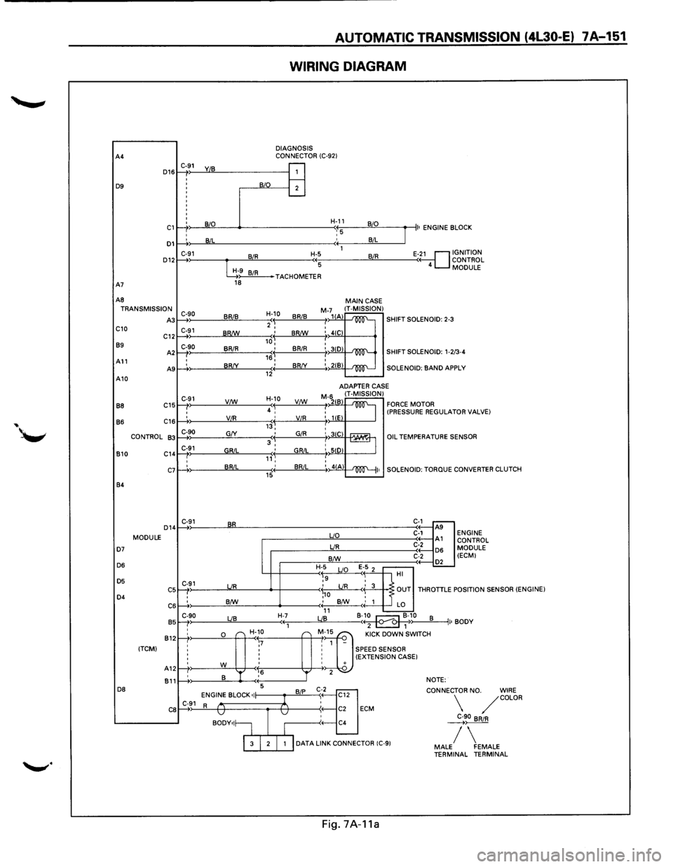
AUTOMATIC TRANSMISSION (4l30-E) 7 A-151
WIRING DIAGRAM
DIAGNOSIS
CONNECTOR (C-921 C-91
1: : j
B/0 B
I
I B/L
C-91 BIR :
G9 BIR 18
C-90 BRIB )
C-91 ) BR!W
C-90
BRIR I
I BR/Y )
C-91 V/W
'
' VIR )
C-90 G/Y
C-91 GRIL ) '
' BRIL :
C-91 BR
C-91 UR
: B/W
C-90 LIB )
;&"
r-r ,7 ' '
' '
' '
rt' w ,6
' B '
1---+: 5
ENGINE BLOCK •I C-91 R v
BODY•I~
H-11 B/0
'::5 B/L
1
H-5 BIR
(( 5
J
II• ENGINE B LOCK
E-~1 GNITION
ONTROL
MODULE ( 4 c
TACHOMETER
H-10
BRIB 'I 2 I
,J BR!W
I BRIR 16, ' BR/Y (( 12
H-10
4 ~ VC:!:f._
,j VIR
' GIR 3, ' GRIL ,,'~ ' BRIL (( 15
H-7 ((1
---
'r
B/P
1
v
I
MAIN CASE M-71(1 IT-MISSION) /1 A -'m'-SHIFT SOLENOID: 2-3 I I 4(C
: 3(0 -'m'-SHIFT SOLENOID: 1-2 /3-4
:, 21B -'100"'--SOLENOID: BAND AP PLY
ADAPTER
CASE
M-6211 IT-MISSION) FORCE MOTOR I 2 B
~ : liE (PRESSURE REGULAT OR VALVE)
I : 31C rAAUr1 '-== : SID I :, 41A ~I•
uo
UR
B/W
H-5
E 1-5 2 ~9 LIO
'
OIL TEMPERATURES
SOLENOID:
TORQUE
C-1 ..---A9 C-1 A1 C-2 D6 C-2
.-----.£L HI .?
ENSOR
CONVERTER CLUTCH
ENGINE CONTROL
MODULE (ECMI
\,o LIR < 3 OUT THROTTLE P OSITION SENSOR (ENGINE) ; B/W
' 1 LO 11 B-~10 LIB B ( 2 1 ~) II• BODY
"] "" oow' ""''" 1 -
: SPEED SENSOR : (EXTENSION CASE I ' + 2 NOTE:
't]
CONNEC
C12
: C2 ECM
C4 TOR
NO. WIRE /COLOR
~90 BRIR
I 3 I 2 I 1 I DATA LINK CONNECTOR (C-91 / MALE FEMALE TERMINAL TERMINAL
Fig.
7A-11a
Page 1191 of 1928

CHASSIS ELECTRICAL 8-1
·SECTION 8
CHASSIS ELECTRICAL
'\f CAUTION: .
When fasteners are removed, always reinstall them at the same location from which they were removed.
If a fastener needs to be replaced, use the correct part number fastener for that application. If the correct
part number fastener is not
available, a fastener of equal size and strength (or stronger) may be used.
Fasteners that are not reused, and those requiring thread
locking compound, will be called out. The correct
torque
values must be used when installing fasteners that require it. If the above conditions are not
followed, parts or system damage could result.
CONTENTS
General Information .................................... 8-2
Notes for Working on Electrical
Items .................................................... 8-2
Symbols and Abbreviations ................. 8-8
Symbols ............................................ 8-8
Abbreviations ................................... 8-9
Parts for Electrical Circuit ..................... 8-10
Wiring ............................................... 8-10
Fuse .................................................. 8-11
Fusible Link ....................................... 8-12
Circuit Breaker ................................... 8-12
Relay ................................................. 8-12
Relay Specifications and
Configurations ................................ 8-13
Diode ................................................. 8-14
Connector ......................................... 8-15
Reading the Circuit Diagram ................ 8-17
Main Data and Specifications .................... 8-19
Bulb Specifications ................................ 8-19
Fuse,
Fusible Link and
Circuit Breaker Location ..................... 8-21
Fuse
Block Circuit .................................. 8-22
Reference Table of Fuse, Fusible
Link and Circuit Breaker ..................... 8-23
Relay Location ....................................... 8-27
Diode Location .......................................
8-28
Grounding Point .................................... 8-29
Reference Table ................................ 8-29
Location ............................................ 8-31
Cable Harness Routing .......................... 8-34
System Repair .............................................. 8-38
Start and Charging ................................ 8-38
Engine Control Module
(ECM) ................................................... 8-47
Headlight and Fog Light ........................ 8-58
Front Side Marker Light, Parking Light,
Taillight, License Plate Light and
Illumination Light .............................. 8-76
Stoplight and Rear Defogger .............. 8-92
Turn Signal Light, Hazard
Warning
Light, Cornering Light,
Backup
Light and Horn ..................... 8-106
Dome Light, Luggage room Light,
Courtesy Light, Map Light,
Seat Belt Switch and
Warning Buzzer ................................. 8-128
Power Door Lock ................................. 8-142
Power
Window .................................... 8-156
Cruise
Control ...................................... 8-172
Anti-Lock Brake
System (ABS) ........... 8-178
Rear
Wheel Anti-Lock Brake
System (RWAL) ................................. 8-185
Transmission
Control Module
(TCM) ................................................. 8-192
A/T Shift Lock ...................................... 8-200
Windshield
Wiper/Washer and
Rear
Wiper/Washer .......................... 8-205
Headlight wiper /washer ..................... 8-232
Audio, Auto Antenna,
Cigarette
Lighter and digital clock ... 8-246
Power Door Mirror ............................... 8-254
Anti-theft System ................................ 8-270
Meter and Warning/Indicator Light ... 8-288
A/T Shift Indicator ............................... 8-336
Heater and
Air Conditioning ............... 8-340
Sun
Roof ............................................... 8-346
Power Seat ........................................... 8-360
Seat
Heater .......................................... 8-37 4
Supplemental Restraint
System (SRS) -AIR BAG ................... 8-382
Page 1192 of 1928
-·*; ~---
8-2 CHASSIS ELECTRICAL
GENERAL INFORMATION
The chassis electrical system is of 12-volt specifications with a negative ground polarity.
Wire sizes are appropriate
to respective circuits, and classified by color. (The classification of harnesses by
color is shown on the circuit diagram for ease of harness identification.)
The
wire size is determined by load capacity and the length of wire required.
The
vehicle harnesses are: body harness, chassis harness, engine room harness, instrument harness,
transmission harness, engine
ECGI harness, dome light harness, door harness, rear body harness, tailgate
harness,
SRS harness and battery cables.
The harnesses are protected either
by tape or corrugated tube, depending on harness location.
The circuit
for each system consists of the power source, wire, fuse, relay, switch, load parts and ground, all of
which are shown on the circuit diagram.
In this manual, each electrical device is classified by system. For major parts shown on the circuit based on
the circuit diagram
for each system, a summary, diagnosis oftroubles, inspection and removal and installation
procedures are detailed.
NOTES FOR WORKING ON ELECTRICAL ITEMS
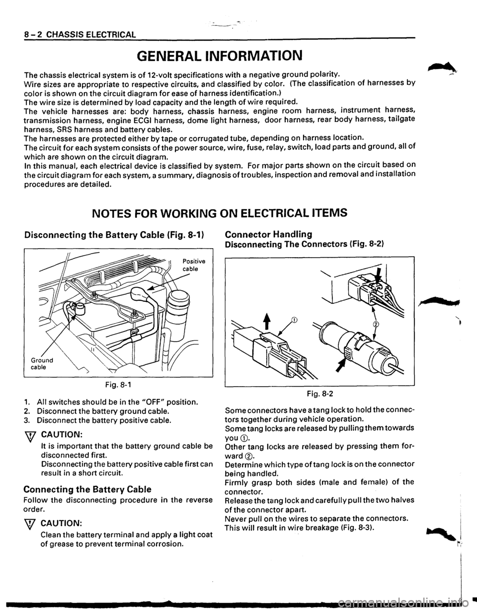
Disconnecting the Battery Cable (Fig. 8-1)
Ground cable
Fig. 8-1
1. All switches should be in the "OFF" position.
2. Disconnect the battery ground cable.
3. Disconnect the battery positive cable.
W CAUTION:
It is important that the battery ground cable be
disconnected first.
Disconnecting the battery positive cable first can
result in a short circuit.
Connecting the Battery Cable
Follow the disconnecting procedure in the reverse
order.
\V CAUTION:
Clean the battery terminal and apply a light coat
of grease to prevent terminal corrosion.
Connector Handling
Disconnecting The Connectors (Fig. 8-2)
Fig. 8-2
Some connectors have a tang lock to hold the connec
tors together during vehicle operation.
Some tang locks are released by pulling them towards
you
G).
Other tang locks are released by pressing them for
ward®.
Determine which type oftang lock is on the connector
being handled.
Firmly grasp both sides (male and female)
of the
connector. Release the tang lock and carefully pull the
two halves
of the connector apart.
Never pull on the wires
to separate the connectors.
This
will result in wire breakage (Fig. 8-3).
.,
..
Page 1200 of 1928
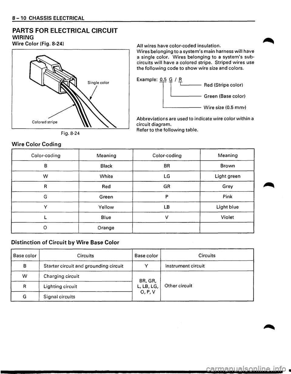
8-10 CHASSIS ELECTRICAL
PARTS FOR ELECTRICAL CIRCUIT
WIRING
Wire Color (Fig. 8-24)
Fig. 8-24
Wire Color Coding
Color-coding Meaning
B Black
w White
R
Red
G Green
y
Yellow
L Blue
0 Orange
Distinction of Circuit by Wire Base Color
Base color Circuits
B
Starter circuit and grounding circuit
w Charging circuit
R Lighting circuit
G Signal circuits
All wires have color-coded insulation.
Wires belon{)ing to a system's main harness will have
a
single color. Wires belonging to a system's sub
circuits will have a colored stripe. Striped wires use
the followinu code to show wire size and colors.
j '-----Red (Stripe color) Example:
1
0.!~ TL.-~-~---
Green (Base color)
------Wire size (0.5 mm•)
Abbreviations are used to indicate wire color within a
circuit diagram.
Refer to the following table.
Color-coding Meaning
BR Brown
LG Light green
GR Grey
p Pink
LB Light blue
v Violet
Base color Circuits
y
Instrument circuit
BR, GR,
L, LB, LG, Other circuit
O,P,V