sensor ISUZU TROOPER 1995 Manual PDF
[x] Cancel search | Manufacturer: ISUZU, Model Year: 1995, Model line: TROOPER, Model: ISUZU TROOPER 1995Pages: 1928
Page 475 of 1928
4-WHEEL ANTILOCK BRAKE SYSTEM (ABS) 5A4-65
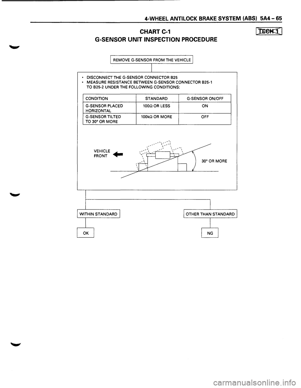
CHART C-1
G-SENSOR UNIT INSPECTION PROCEDURE
REMOVE G-SENSOR FROM THE VEHICLE
• DISCONNECT
THE G-SENSOR CONNECTOR 825 • MEASURE RESISTANCE 8ElWEEN G-SENSOR CONNECTOR 825-1 TO 825-2 UNDER THE FOLLOWING CONDITIONS:
CONDITION
G-SENSOR
PLACED HORIZONTAL
G-SENSOR TILTED
TO 30°
OR MORE
VEHICLE ...........
FRONT
~
STANDARD G-SENSOR ON/OFF
1000 OR LESS ON
100kn OR MORE OFF
30°
OR MORE
[)EeH:(I
Page 476 of 1928
5A4-66 4-WHEEL ANTILOCK BRAKE SYSTEM (ASS)
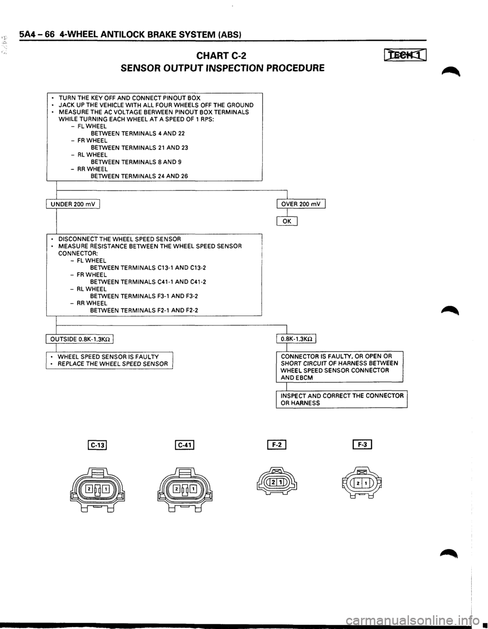
CHART C-2
SENSOR
OUTPUT INSPECTION PROCEDURE
• TURN THE KEY OFF AND CONNECT PINOUT BOX
• JACK UP THE VEHICLE WITH ALL FOUR WHEELS OFF THE GROUND . MEASURE THE AC VOLTAGE BERWEEN PINOUT BOX TERMINALS
WHILE TURNING EACH WHEEL AT A SPEED OF 1 RPS:
-FLWHEEL BETWEEN TERMINALS 4 AND 22
I
-FR WHEEL
BETWEEN TERMINALS 21 AND 23
-RL WHEEL BETWEEN TERMINALS 8 AND 9
-RR WHEEL BETWEEN TERMINALS 24 AND 26
I UNDER 200 mV I OVER 200 mV J
0
DISCONNECT THE WHEEL SPEED SENSOR
• MEASURE RESISTANCE BETWEEN THE WHEEL SPEED SENSOR
CONNECTOR:
-FLWHEEL BETWEEN TERMINALS C13-1 AND C13-2 -FR WHEEL
BETWEEN TERMINALS C41-1 AND C41-2 -RLWHEEL BETWEEN TERMINALS F3-1 AND F3-2
- RRWHEEL
BETWEEN
TERMINALS F2-1 AND F2-2
I OUTSIDE 0.8K-1.3Kn I 0.8K-1.3KO j
I • WHEEL SPEED SENSOR IS FAULTY I CONNECTOR IS FAUL TV. OR OPEN OR • REPLACE THE WHEEL SPEED SENSOR SHORT
CIRCUIT OF HARNESS BETWEEN
WHEEL SPEED SENSOR CONNECTOR ANDEBCM
I
INSPECT AND CORRECT THE CONNECTOR I OR HARNESS
•
Page 477 of 1928
4-WHEEL ANTILOCK BRAKE SYSTEM (ABS) 5A4-67
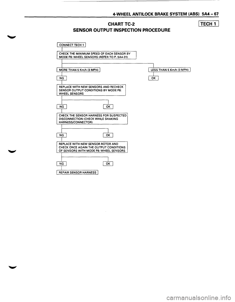
CHARTTC-2
SENSOR OUTPUT INSPECTION PROCEDURE
CHECK THE MINIMUM SPEED OF EACH SENSOR BY MODE F6: WHEEL SENSORS (REFER TOP. 5A4-31)
REPLACE
WITH NEW SENSORS AND RECHECK SENSOR OUTPUT CONDITIONS BY MODE F6: WHEEL SENSORS
CHECK THE
SENSOR HARNESS FOR SUSPECTED
DISCONNECTION (CHECK WHILE SHAKING HARNESS/CONNECTOR)
REPLACE
WITH NEW SENSOR ROTOR AND CHECK ONCE AGAIN THE OUTPUT CONDITIONS OF SENSORS WITH MODE F6: WHEEL SENSORS
I TECH 1 I
Page 485 of 1928
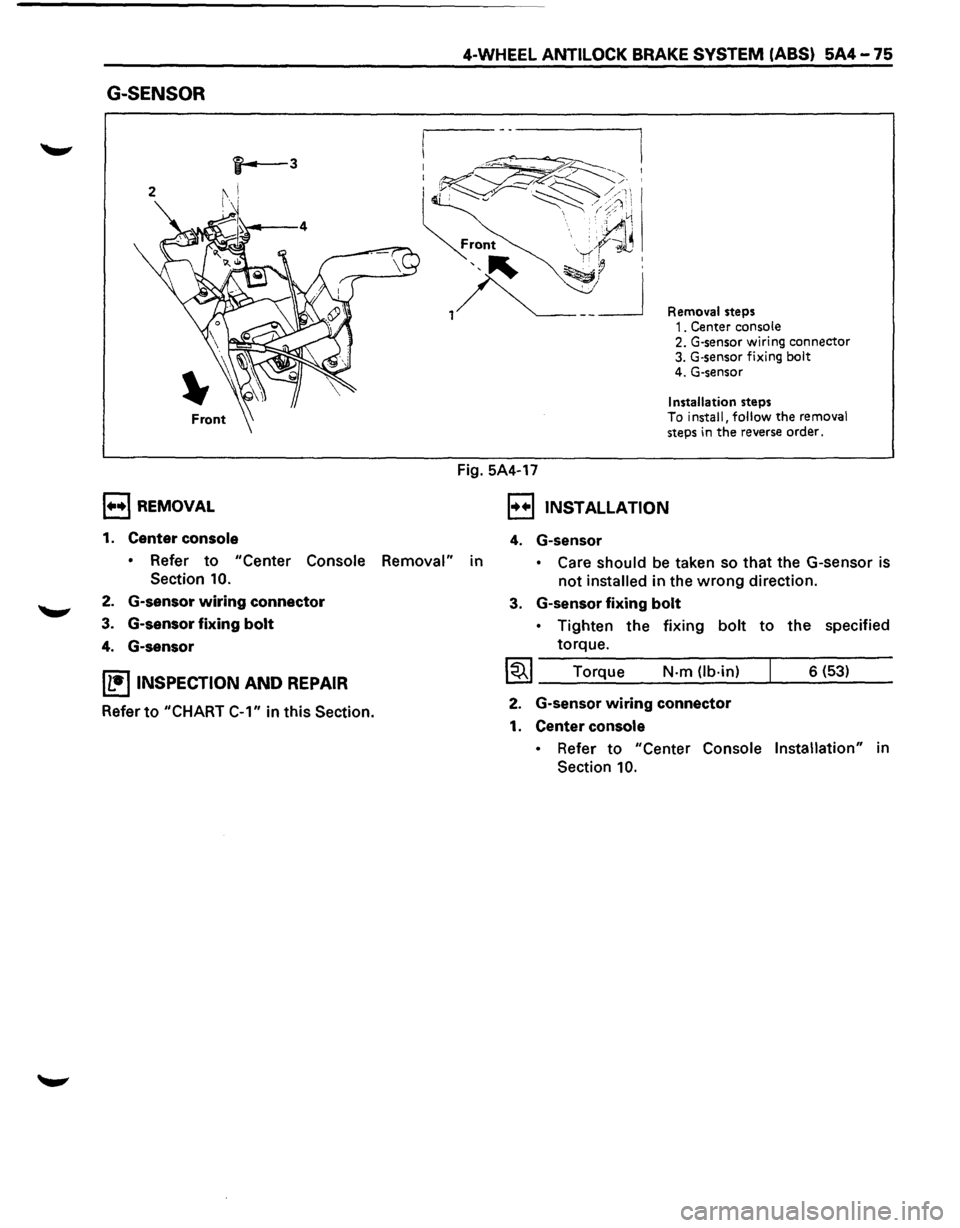
G-SENSOR
, .... ,REMOVAL
1. Center console
4-WHEEL ANTILOCK BRAKE SYSTEM (ABS) 5A4-75
Fig. 5A4-17
Removal steps 1. Center console 2. G-sensor wiring connector 3. G·sensor fixing bolt 4. G-sensor
Installation steps To install, follow the removal steps in the reverse order.
, .. .,, INSTALLATION
4. G-sensor
• Refer to "Center Console Removal" in • Care should be taken so that the G-sensor is
not installed in the wrong direction.
Section 10.
2. G-sensor wiring connector
3. G-sensor fixing bolt
4. G-sensor
IL•ItNSPECTION AND REPAIR
Refer to "CHART
C-1" in this Section.
3. G-sensor fixing bolt
• Tighten the fixing bolt to the specified
torque.
I~I ____ T_o_rq~u~e ____ N~·-m~(lb_·_in~)--~ ___ 6_(_53~) __ __
2. G-sensor wiring connector
1. Center console
• Refer to "Center Console Installation" in
Section
10.
Page 486 of 1928
if.. ~ ' -
5A4-76 4-WHEEL ANTILOCK BRAKE SYSTEM (ABS)
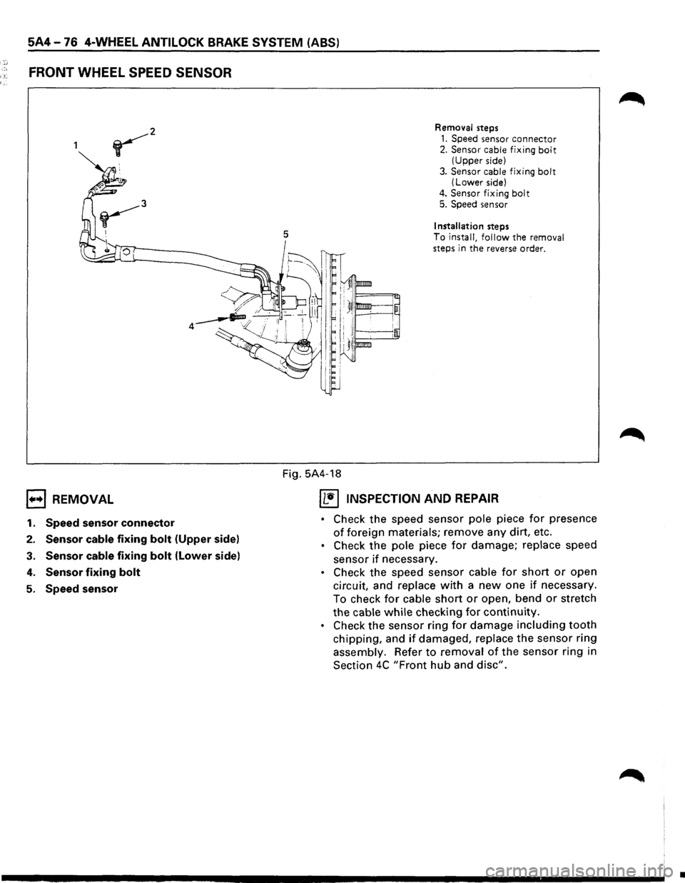
FRONT WHEEL SPEED SENSOR
1••1 REMOVAL
1. Speed sensor connector
2. Sensor cable fixing bolt (Upper side)
3. Sensor cable fixing bolt (Lower side)
4. Sensor fixing bolt
5. Speed sensor
5
Removal steps
1. Speed sensor connector 2. Sensor cable fixing bolt (Upper side)
3.
Sensor cable fixing bolt (Lower side)
4. Sensor fixing bolt 5. Speed sensor
Installation steps
To install, follow the removal
steps in the reverse order.
Fig. 5A4-18
IL•IINSPECTION AND REPAIR
• Check the speed sensor pole piece for presence
of foreign materials; remove any dirt, etc.
• Check the pole piece for damage; replace speed
sensor
if necessary.
• Check the speed sensor cable for short or open
circuit, and replace
with a new one if necessary.
To check
for cable short or open, bend or stretch
the
cable while checking for continuity.
• Check the sensor ring for damage including tooth
chipping, and if damaged, replace the sensor ring
assembly. Refer
to removal of the sensor ring in
Section
4C "Front hub and disc".
•
Page 487 of 1928
I••! INSTALLATION
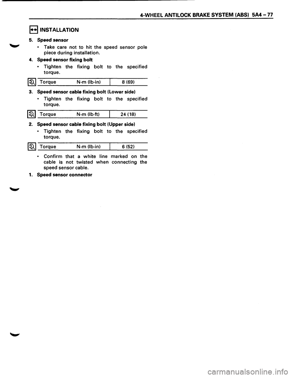
5. Speed sensor
4-WHEEL ANTILOCK BRAKE SYSTEM (ABS) 5A4-77
,.....,. • Take care not to hit the speed sensor pole
piece during installation.
4. Speed sensor fixing bolt
• Tighten the fixing bolt to the specified
torque.
1~1 Torque N·m (lb·in) 8 (69)
3. Speed sensor cable fixing bolt (lower side)
• Tighten the fixing bolt to the specified
torque.
~~~ Torque N·m (lb-ft) 24 (18)
2. Speed sensor cable fixing bolt (Upper side)
• Tighten
torque.
1~1 Torque the
fixing
bolt to the specified
N-m (lb·in) 6 (52)
• Confirm that a white line marked on the
cable is not twisted when connecting the
speed sensor
cable.
1. Speed sensor connector
Page 488 of 1928
5A4-78 4-WHEEL ANTILOCK BRAKE SYSTEM (ABS)
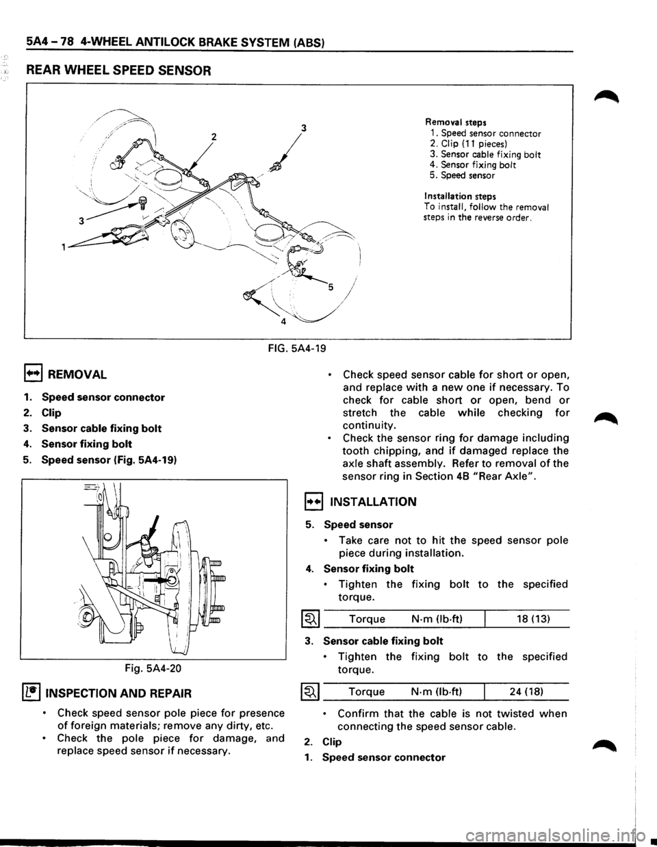
REAR WHEEL SPEED SENSOR
3 Removal steps
2
/
1. Speed sensor connector 2. Clip (11 pieces)
3.
Sensor cable fixing bolt 4. Sensor fixing bolt 5. Speed sensor
j
/
Installation steps
To
install, follow the removal
steps in the reverse order.
FIG. 5A4-19
1+•1 REMOVAL
1. Speed sensor connector
2. Clip
3. Sensor cable fixing bolt
4. Sensor fixing bolt
5. Speed sensor (Fig. 5A4-19)
Fig.
5A4-20
IL•ItNSPECTION AND REPAIR
• Check speed sensor pole piece for presence
of foreign materials; remove any dirty, etc.
• Check the pole piece for damage, and
replace speed sensor if necessary.
• Check speed sensor cable for short or open,
and
replace with a new one if necessary. To
check
for cable short or open, bend or
stretch the cable while checking for
continuity.
• Check the sensor ring for damage including
tooth chipping, and if damaged replace the
axle shaft assembly. Refer to removal of the
sensor ring in
Section 48 "Rear Axle".
,,..,,INSTALLATION
5. Speed sensor
• Take care not to hit the speed sensor pole
piece during installation.
4. Sensor fixing bolt
• Tighten the fixing bolt to the specified
torque.
I~I ____ T_o_rq~u_e ____ N __ ·m __ O_b·_ft_) __ ~ ____ 18_(_1_3_) __
3. Sensor cable fixing bolt
• Tighten the fixing bolt to the specified
torque.
~~~ Torque N·m (lb.ft) 24 (18)
• Confirm that the cable is not twisted when
connecting the speed sensor cable.
2. Clip
1. Speed sensor connector
•
Page 503 of 1928
ENGINE DIAGNOSIS 6-5
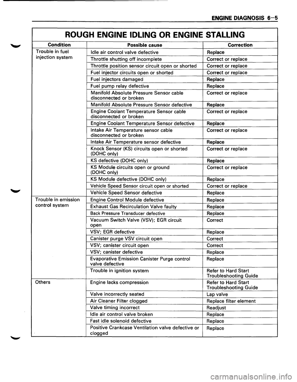
ROUGH ENGINE IDLING OR ENGINE STALLING
Condition Possible cause Correction
Trouble in fuel
Idle air control valve defective Replace
injection system
Throttle shutting
off incomplete Correct or replace
Throttle position sensor circuit open
or shorted Correct or replace
Fuel injector circuits open or shorted Correct or replace
Fuel injectors damaged
Replace
Fuel pump relay defective Replace
Manifold Absolute Pressure Sensor
cable Correct or replace
disconnected
or broken
Manifold Absolute Pressure Sensor defective
Replace
Engine Coolant Temperature Sensor cable Correct
or replace
disconnected
or broken
Engine Coolant Temperature Sensor defective
Replace
Intake Air Temperature sensor cable Correct or replace
disconnected
or broken
Intake Air Temperature sensor defective
Replace
Knock Sensor
(KS) circuits open or shorted
Correct or replace
(DOHC only)
KS defective (DOHC only) Replace
KS Module circuits open or ground
Correct or replace
(DOHC only)
KS Module defective (DOHC only) Replace
Vehicle Speed Sensor circuit open or shorted
Correct or replace
Vehicle Speed Sensor defective
Replace
Trouble in emission
Engine Control Module defective
Replace
control system
Exhaust Gas Recirculation
Valve faulty
Replace
Back Pressure Transducer defective
Replace
Vacuum Switch Valve (VSV); EGR circuit
Correct
open
VSV; EGR defective Replace
Canister purge
VSV circuit open
Correct
VSV; canister circuit open
Correct
VSV; canister defective
Replace
Evaporative Emission Canister Purge control
Replace
valve defective
Trouble in ignition system
Refer
to Hard Start
Troubleshooting Guide
Others Engine lacks compression
Refer to Hard Start
Troubleshooting Guide
Valve incorrectly seated
Lap valve
Air Cleaner Filter clogged
Replace filter element
Valve timing incorrect
Readjust
Idle air control valve broken
Replace
Fast
idle solenoid defective
Replace
Positive Crankcase Ventilation valve defective
or Replace
clogged
Page 504 of 1928
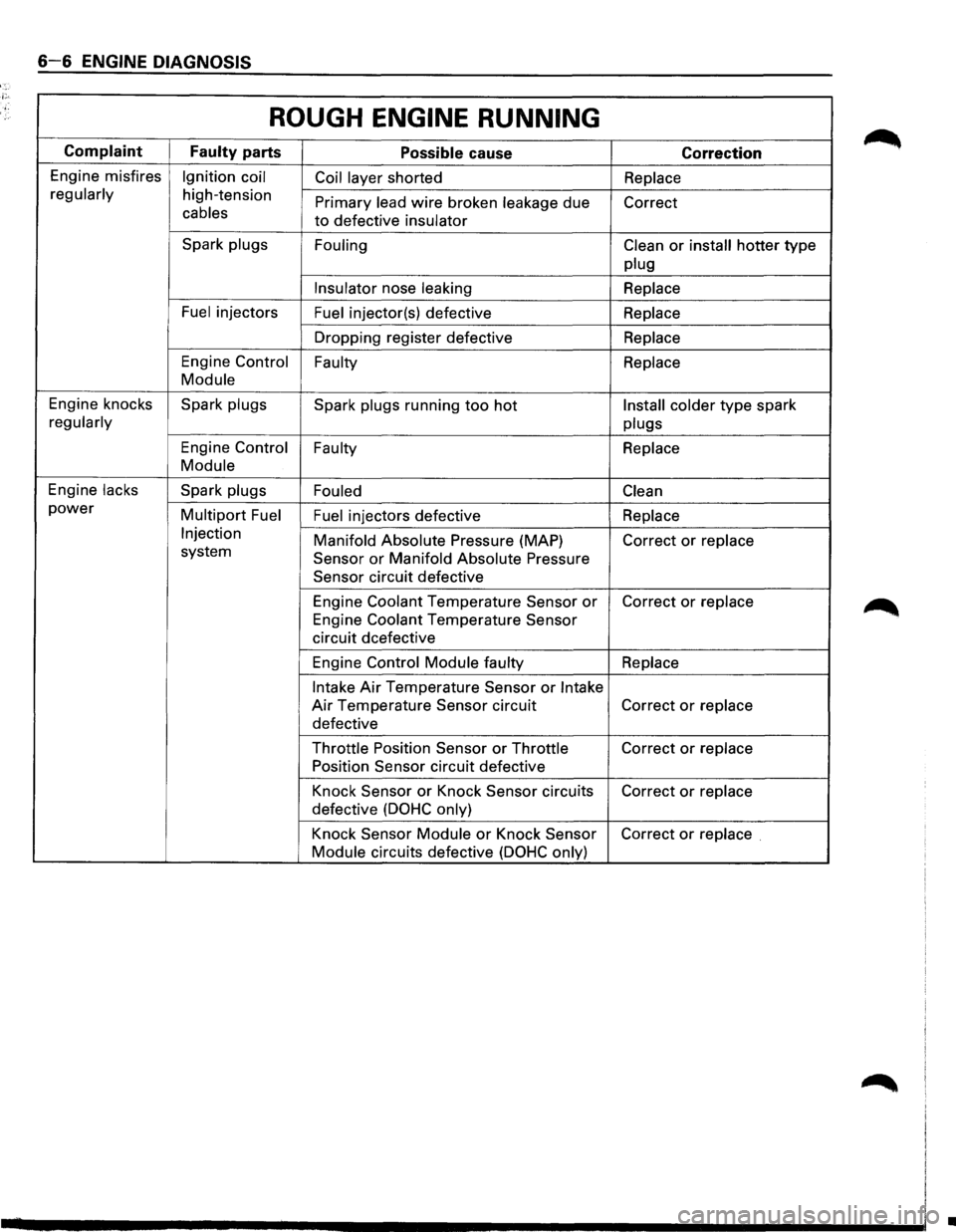
6-6 ENGINE DIAGNOSIS
ROUGH ENGINE RUNNING
Complaint
Faulty parts Possible cause Correction
Engine misfires Ignition coil
Coil layer shorted Replace
regularly
high-tension Primary lead wire broken leakage due
Correct cables to defective insulator
Spark plugs
Fouling Clean
or install hotter type
plug
Insulator
nose leaking Replace
Fuel
injectors Fuel injector(s) defective Replace
Dropping register defective Replace
Engine Control
Faulty Replace
Module
Engine knocks Spark plugs
Spark plugs running too hot Install colder type spark
regularly
plugs
Engine Control Faulty
Replace
Module
Engine lacks Spark plugs
Fouled Clean
power Multipart Fuel
Fuel injectors defective Replace
Injection Manifold Absolute Pressure (MAP)
Correct or replace system Sensor or Manifold Absolute Pressure
Sensor
circuit defective
Engine
Coolant Temperature Sensor or Correct or replace
Engine Coolant Temperature Sensor
circuit dcefective
Engine
Control Module faulty Replace
Intake
Air Temperature Sensor or Intake
Air Temperature Sensor circuit Correct or replace
defective
Throttle Position Sensor or Throttle Correct or replace
Position Sensor
circuit defective
Knock
Sensor or Knock Sensor circuits Correct or replace
defective (DOHC only)
Knock Sensor Module or Knock Sensor Correct or replace .
Module
circuits defective (DOHC only)
•
Page 505 of 1928
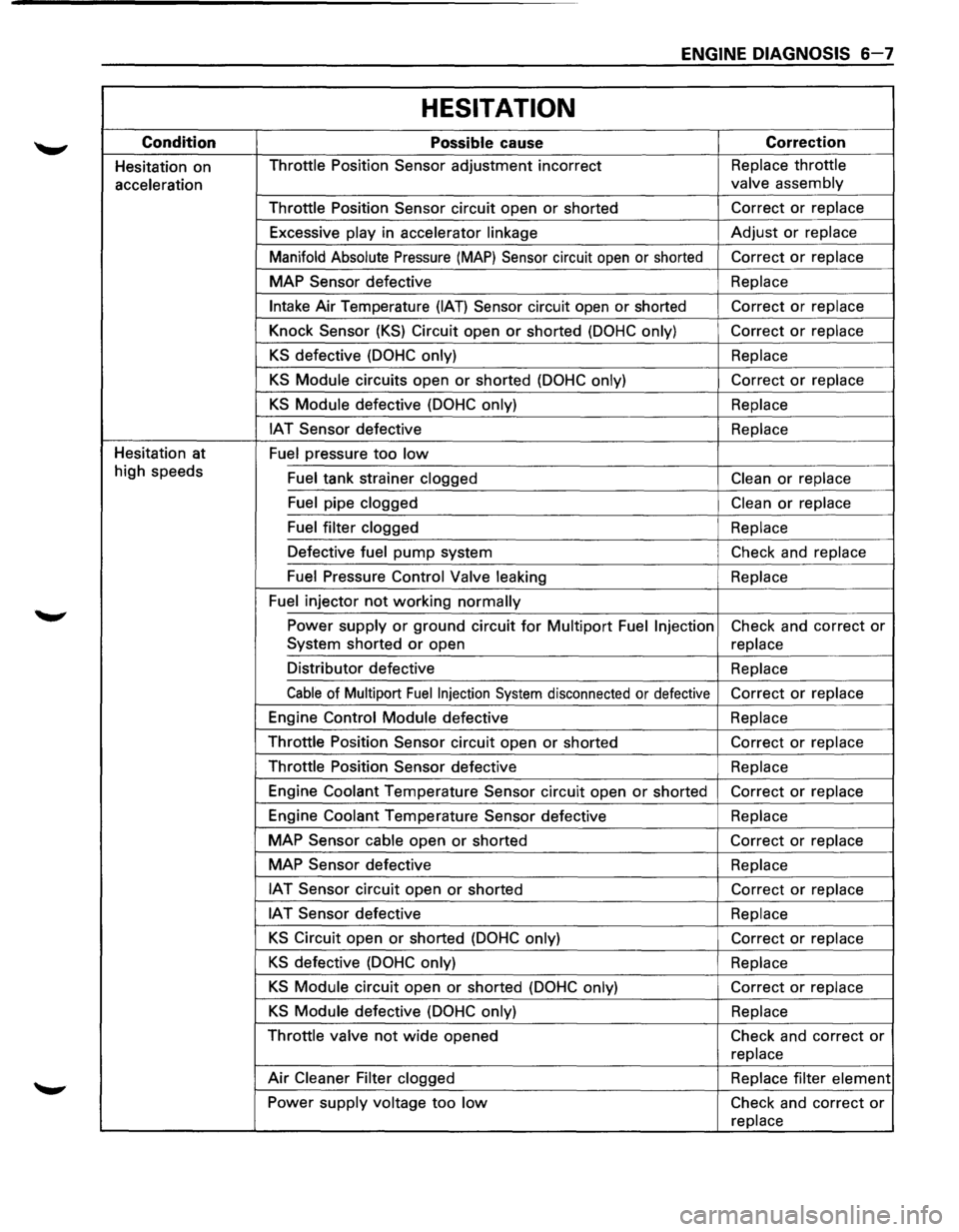
ENGINE DIAGNOSIS 6-7
HESITATION
Condition Possible cause Correction
Hesitation on Throttle
Position Sensor adjustment incorrect Replace
throttle
acceleration valve
assembly
Throttle Position Sensor circuit open
or shorted Correct
or replace
Excessive play in accelerator linkage
Adjust or replace
Manifold Absolute
Pressure (MAP) Sensor circuit open or shorted Correct or replace
MAP Sensor defective Replace
Intake Air
Temperature (IAT) Sensor circuit open or shorted Correct or replace
Knock Sensor
(KS) Circuit open or shorted (DOHC only) Correct or replace
KS defective (DOHC only) Replace
KS Module circuits open or shorted (DOHC only) Correct or replace
KS Module defective (DOHC only) Replace
IAT Sensor defective Replace
Hesitation at
Fuel pressure
too low
high speeds
Fuel tank strainer clogged Clean or replace
Fuel pipe clogged
Clean or replace
Fuel filter clogged
Replace
Defective fuel
pump system Check and replace
Fuel Pressure Control Valve leaking Replace
Fuel injector
not working normally
Power supply or ground circuit for Multipart Fuel Injection Check and correct or
System shorted or open
replace
Distributor defective Replace
Cable of Multipart Fuel Injection System disconnected or defective Correct or replace
Engine Control Module defective Replace
Throttle Position Sensor circuit open
or shorted Correct or replace
Throttle Position Sensor defective Replace
Engine Coolant Temperature Sensor circuit open
or shorted Correct or replace
Engine Coolant Temperature Sensor defective Replace
MAP Sensor cable open
or shorted Correct or replace
MAP Sensor defective
Replace
IAT Sensor circuit open or shorted
Correct or replace
IAT Sensor defective Replace
KS Circuit open or shorted (DOHC only)
Correct or replace
KS defective (DOHC only) Replace
KS Module circuit open or shorted (DOHC only) Correct or replace
KS Module defective (DOHC only) Replace
Throttle valve
not wide opened
Check and correct or
replace
Air Cleaner Filter clogged
Replace filter element
Power supply voltage
too low Check and correct or
replace