sensor ISUZU TROOPER 1995 Workshop Manual
[x] Cancel search | Manufacturer: ISUZU, Model Year: 1995, Model line: TROOPER, Model: ISUZU TROOPER 1995Pages: 1928
Page 713 of 1928
DRIVEABILITY AND EMISSIONS 6E2-17
I OPERATING CONDITIONS READ I
I SYSTEMS CONTROLLED I
• Air Conditioning "On" or "Off" • Evaporative Emission Canister
• Engine Coolant Temperature Purge
• Crankshaft Position • Exhaust Gas Recirculation
• Exhaust Heated Oxygen Sensor • Ignition Control
• Electronic Ignition Reference • Fuel Control
• Crankshaft Position
ENGINE • Idle Air Control
• Engine Speed (RPM} CONTROL • Electric Fuel Pump
• Manifold Absolute Pressure (MAP)
MODULE • Air Conditioning
• Battery Positive Voltage (ECM) • Diagnostics
• Throttle Position Sensor • Malfunction Indicator Lamp
• Vehicle Speed Sensor • Diagnostic Test Terminal
• Fuel Pump Voltage • Data Output
• Power Steering Pressure • Transmission Control Module
• Intake Air Temperature • Knock Sensor (DOHC)
• Differential Pressure • Induction Air Control Plate System
• Knock Sensor (DOHC)
(DOHC)
• Exhaust Gas Recirculation Vacuum
• Air Conditioning High Side Pressure
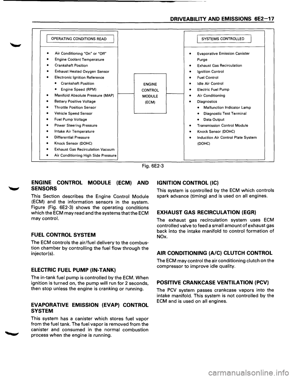
Fig. 6E2-3
ENGINE CONTROL MODULE (ECM) AND
SENSORS
This Section describes the Engine Control Module
(ECM) and the information sensors in the system.
Figure (Fig. 6E2-3) shows the operating conditions
which the
ECM may read and the systems thatthe ECM
may control.
FUEL CONTROL SYSTEM
The ECM controls the air/fuel delivery to the combus
tion chamber by
controlling the fuel flow through the
injector(s).
ELECTRIC FUEL PUMP (IN-TANK)
The in-tank fuel pump is controlled by the ECM. When
ignition is turned on, the
pump will run for 2 seconds,
then stop
unless the engine is cranking or running.
EVAPORATIVE EMISSION (EVAP) CONTROL
SYSTEM
This system has a canister which stores fuel vapor
from the fuel tank. The fuel vapor is removed from the
canister and consumed in the
normal combustion
process when the engine
is running.
IGNITION CONTROL (IC)
This system is controlled by the ECM which controls
spark advance (timing) and is used on all engines.
EXHAUST GAS RECIRCULATION (EGR)
The exhaust gas recirculation system uses ECM
controlled valve to feed a small amount of exhaust gas
back into the intake
manifold to control formation of
NOx.
AIR CONDITIONING (A/C) CLUTCH CONTROL
The ECM may control the air conditioning clutch on the
compressor
to improve idle quality.
POSITIVE CRANKCASE VENTILATION (PCV)
The PCV system passes crankcase vapors into the
intake
manifold. This system is not controlled by the
ECM and is used on all engines.
Page 714 of 1928
6E2-18 DRIVEABILITV AND EMISSIONS
TOOLS NEEDED TO SERVICE THE SVSJEM
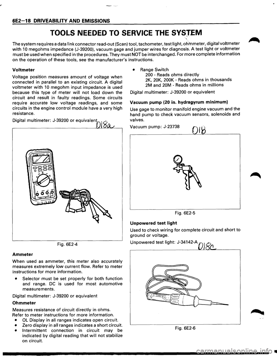
The system requires a data link connector read-out (Scan) tool, tachometer, test light, ohmmeter, digital voltmeter
with 10 megohms impedance (J-39200), vacuum gage and jumper wires for diagnosis. A test light or voltmeter
must be used when specified in the procedures. They must NOT be interchanged. For more complete information
on the operation
of these tools, see the manufacturer's instructions.
Voltmeter
Voltage position measures amount of voltage when
connected in
parallel to an existing circuit. A digital
voltmeter
with 10 megohm input impedance is used
because this type
of meter will not load down the
circuit and
result in faulty readings. Some circuits
require accurate
low voltage readings, and some
circuits in the engine
control module have a very high
resistance.
Digital multimeter: J-39200 or equivalent
Fig. 6E2-4
Ammeter
When used as ammeter, this meter also accurately
measures extremely low current flow. Refer to meter
instructions
for more information.
• Selector must be set properly for both function
and range.
DC is used for most automotive
measurements.
Digital multimeter: J-39200 or equivalent
Ohmmeter
Measures resistance of circuit directly in ohms.
Refer to meter instructions
for more information.
• OL Display in all ranges indicates open circuit.
• Zero display in all ranges indicates a short circuit.
• Intermittent connection in circuit may be
indicated by digital reading that will not stabilize
on circuit.
• Range Switch
200 -Reads ohms
directly
2K, 20K, 200K -Reads ohms in thousands
2M and 20M -Reads ohms in
millions
Digital multimeter:
J-39200 or equivalent
Vacuum pump (20 in. hydragyrum minimum)
Use gage to monitor manifold engine vacuum and the
hand pump to check vacuum sensors,
solenoids and
valves.
Vacuum pump: J-23738
Fig. 6E2-5
Unpowered test light
Used to check wiring for complete circuit and short to
ground
or voltage.
Unpowered test light: J-34142-A
Fig. 6E2-6
•
Page 718 of 1928
6E2-22 DRIVEABILITV AND EMISSIONS
(DOHC)
(SOHC)
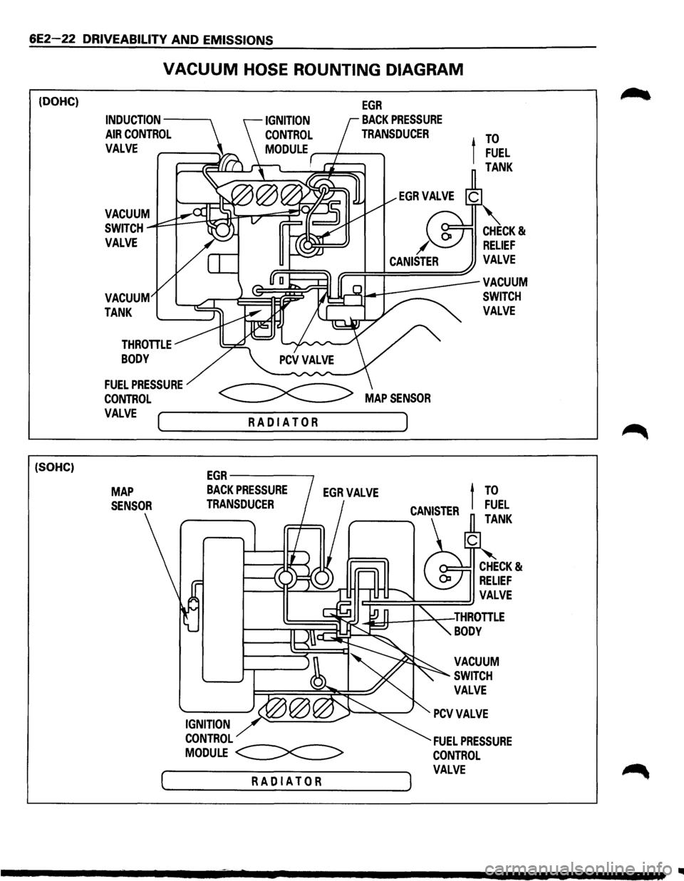
VACUUM HOSE ROUNTING DIAGRAM
EGR
INDUCTION-----
AIR CONTROL
VALVE
BACK PRESSURE
TRANSDUCER
t
TO
THROTTLE
BODY
FUELPRESSURE ~
CONTROL ~ MAPSENSOR
VALVE (..._ _____ R_A_D _I A_T_O_R ____ ___.)
MAP
SENSOR
EGR------,
BACK PRESSURE
TRANSDUCER
FUEL
TANK
VACUUM
SWITCH
VALVE
CHECK&
RELIEF
c:::=::::::::::::::;:T=====!.J VALVE
L-~~~~~ ...J;::...u..-+----'~THROTTLE BODY
IGNITION
CONTROL
MODULE <==><==::>
[ RADIATOR )
~---------------------
VACUUM
SWITCH
VALVE
FUEL PRESSURE
CONTROL
VALVE
..
Page 719 of 1928
DRIVEABILITY AND EMISSIONS 6E2-23
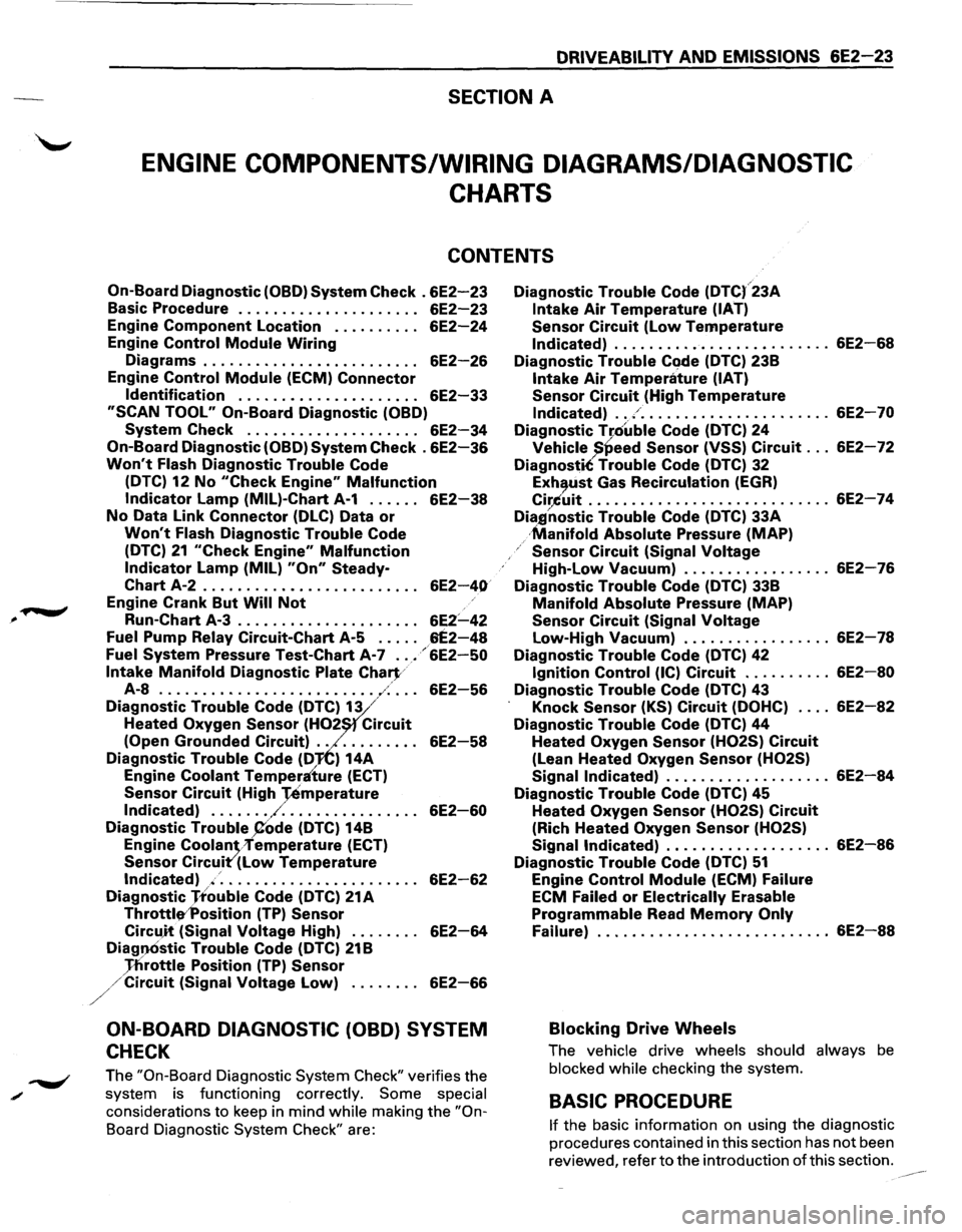
SECTION A
ENGINE COMPONENTS/WIRING DIAGRAMS/DIAGNOSTIC
CHARTS
CONTENTS
On-Board Diagnostic (OBD} System Check . 6E2-23
Basic Procedure . . . . . . . . . . . . . . . . . . . . . 6E2-23
Engine Component Location . . . . . . . . . . 6E2-24
Engine Control Module Wiring
Diagrams . . . . . . . . . . . . . . . . . . . . . . . . . 6E2-26
Engine Control Module (ECM) Connector
Identification . . . . . . . . . . . . . . . . . . . . . 6E2-33
"SCAN TOOL" On-Board Diagnostic (OBD)
System Check . . . . . . . . . . . . . . . . . . . . 6E2-34
On-Board Diagnostic (OBD} System Check . 6E2-36
Won't Flash Diagnostic Trouble Code
(DTC)
12 No "Check Engine" Malfunction
Indicator Lamp (MIL)-Chart A-1 . . . . . . 6E2-38
No Data Link Connector (DLC) Data or
Won't Flash Diagnostic Trouble Code
(DTC)
21 "Check Engine" Malfunction
Indicator Lamp (MIL} "On" Steady-
Chart A-2 . . . . . . . . . . . . . . . . . . . . . . . . . 6E2-40
Engine Crank But Will Not
Run-Chart A-3 . . . . . . . . . . . . . . . . . . . . . 6E2:.....42
Fuel Pump Relay Circuit-Chart A-5 . . . . . 6E2-48
Fuel System Pressure Test-Chart A-7 ..• /6E2-50
Intake Manifold Diagnostic Plate Chart/
A-8 ......................... ,-:· . . . 6E2-56
Diagnostic Trouble Code (DTC~13 /
Heated Oxygen Sensor (H02 Circuit
(Open Grounded Circuit) . . . . . . . . . . . 6E2-58
Diagnostic Trouble Code (D'JiC) 14A
Engine Coolant Temperaiure (ECT}
Sensor Circuit (High -:remperature
Indicated) ....... /. . . . . . . . . . . . . . . . 6E2-60
Diagnostic Trouble P'ode (DTC} 14B
Engine
Coolan·vremperature (ECT)
Sensor Circuit'(Low Temperature
Indicated) ./. . . . . . . . . . . . . . . . . . . . . . . 6E2-62
Diagnostic Jtouble Code (DTC) 21A
Throtti~,.Position (TP) Sensor
Circu)t (Signal Voltage High) . . . . . . . . 6E2-64
Diag.,Ostic Trouble Code (DTC) 21B
Jflrottle Position (TP} Sensor
//Circuit (Signal Voltage Low} ........ 6E2-66
ON-BOARD DIAGNOSTIC (OBD) SYSTEM
CHECK
The "On-Board Diagnostic System Check" verifies the
system is functioning correctly.
Some special
considerations
to keep in mind while making the "On
Board Diagnostic System Check" are:
Diagnostic Trouble Code (DTC(23A
Intake Air Temperature (IAT)
Sensor Circuit (low Temperature
Indicated) ......................... 6E2-68
Diagnostic Trouble Code (DTC) 23B
Intake Air Temperature (IAT)
Sensor Circuit (High Temperature
Indicated) ... / ...................... 6E2-70
Diagnostic T[ouble Code (DTC} 24
Vehicle )!Peed Sensor (VSS} Circuit ... 6E2-72
DiagnostiC Trouble Code (DTC) 32
Exh,tist Gas Recirculation (EGR}
Cir,.Cuit ............................ 6E2-74
Dia,gnostic Trouble Code (DTC} 33A
·Manifold Absolute Pressure (MAP)
Sensor Circuit (Signal Voltage
High-Low Vacuum) ................. 6E2-76
Diagnostic Trouble Code (DTC) 33B
Manifold Absolute Pressure (MAP}
Sensor Circuit (Signal Voltage
Low-High Vacuum) ................. 6E2-78
Diagnostic Trouble Code (DTC) 42
Ignition Control (IC) Circuit . . . . . . . . . . 6E2-80
Diagnostic Trouble Code (DTC} 43
Knock Sensor (KS} Circuit (DOHC) .... 6E2-82
Diagnostic Trouble Code (DTC) 44
Heated Oxygen Sensor (H02S} Circuit
(Lean Heated Oxygen Sensor (H02S)
Signal Indicated} . . . . . . . . . . . . . . . . . . . 6E2-84
Diagnostic Trouble Code (DTC) 45
Heated Oxygen Sensor (H02S) Circuit
(Rich Heated Oxygen Sensor (H02S)
Signal Indicated) . . . . . . . . . . . . . . . . . . . 6E2-86
Diagnostic Trouble Code (DTC) 51
Engine Control Module (ECM} Failure
ECM Failed
or Electrically Erasable
Programmable Read Memory Only
Failure} ........................... 6E2-88
Blocking Drive Wheels
The vehicle drive wheels should always be
blocked
while checking the system.
BASIC PROCEDURE
If the basic information on using the diagnostic
procedures contained in this section has
not been
reviewed, refer
to the introduction of this section.
Page 720 of 1928
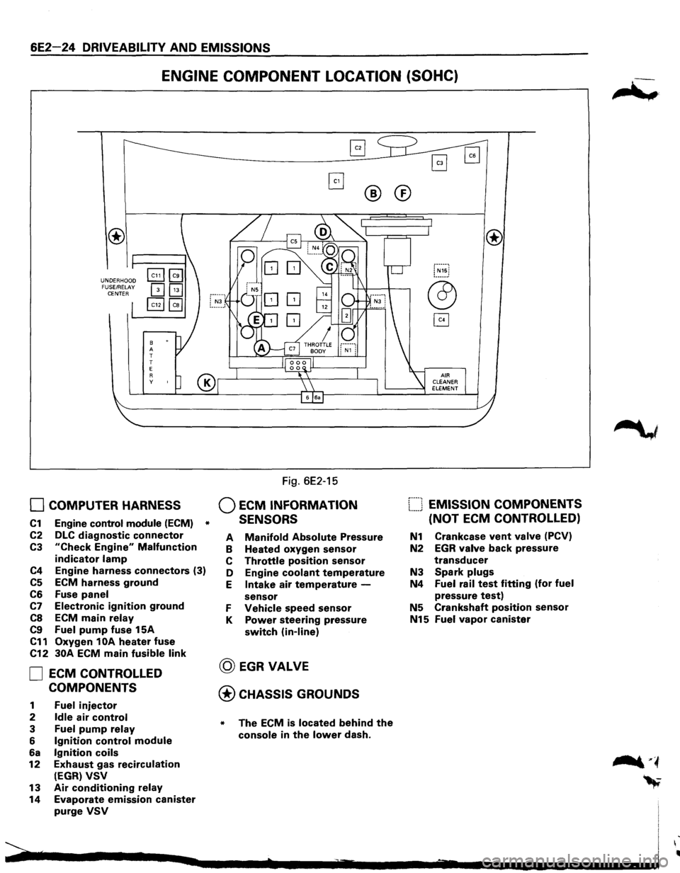
6E2-24 DRIVEABILITY AND EMISSIONS
ENGINE COMPONENT LOCATION (SOHC)
UNDERHOOD
FUSE/RELAY
CENTER
8 A
T
T
E
R y
0 COMPUTER HARNESS
C1 Engine control module (ECM) *
C2 DLC diagnostic connector
C3 "Check Engine" Malfunction
indicator lamp
C4 Engine harness connectors (3)
C5 ECM harness ground
C6 Fuse panel
C7 Electronic ignition ground
CS ECM main relay
C9 Fuel pump fuse 15A
C11 Oxygen 1 OA heater fuse
C12 30A ECM main fusible link
0 ECM CONTROLLED
COMPONENTS
1 Fuel injector
2 Idle air control
3 Fuel pump relay
6 Ignition control module
6a Ignition coils
12 Exhaust gas recirculation
(EGR) VSV
13 Air conditioning relay
14 Evaporate emission canister
purge VSV
Fig. 6E2-15
Q ECM INFORMATION
SENSORS
®
A Manifold Absolute Pressure
B Heated oxygen sensor
C Throttle position sensor
D Engine
coolant temperature
E Intake air temperature -
sensor
F Vehicle speed sensor
K Power steering pressure
switch (in-line)
@ EGRVALVE
@CHASSIS GROUNDS
* The ECM is located behind the
console in the lower dash.
®
[::::J EMISSION COMPONENTS
(NOT
ECM CONTROLLED)
N1 Crankcase vent valve (PCV)
N2 EGR valve back pressure
transducer
N3 Spark plugs
N4 Fuel rail test fitting (for fuel
pressure test)
N5 Crankshaft position sensor
N15 Fuel vapor canister
Page 721 of 1928
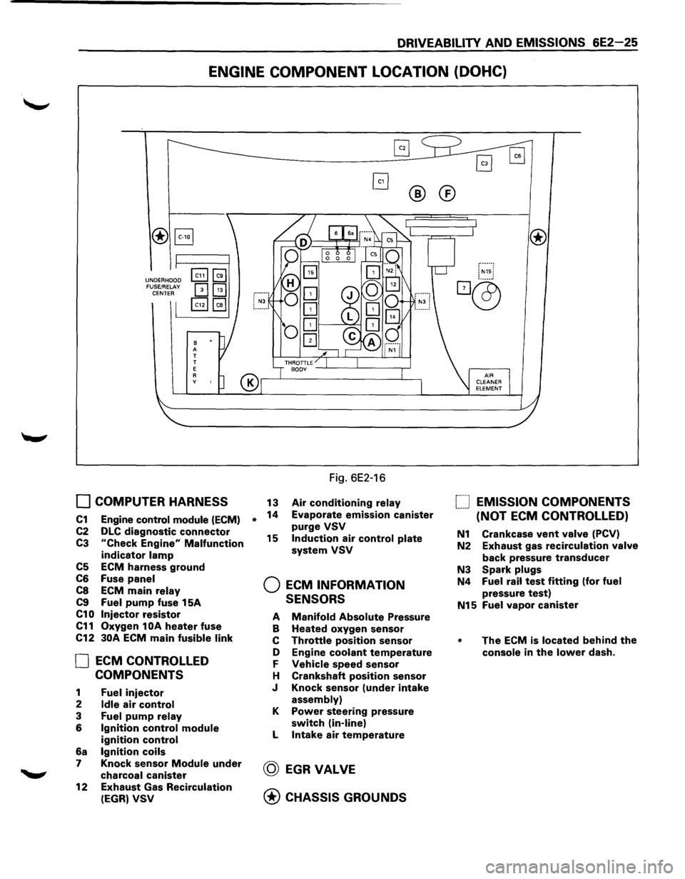
DRIVEABILITY AND EMISSIONS 6E2-25
ENGINE COMPONENT LOCATION (DOHC)
®B
UNDERHOOD FUSE/RELAY CENTER
B A T
T
E
A y
0 COMPUTER HARNESS
C1 Engine control module (ECM)
C2 DLC diagnostic connector
C3 "Check Engine" Malfunction
indicator lamp
C5 ECM harness ground
C6 Fuse panel
C8 ECM main relay
C9 Fuel pump fuse 15A
C10 Injector resistor
C11 Oxygen 1 OA heater fuse
C12
30A ECM main fusible link
0 ECM CONTROLLED
COMPONENTS
1 Fuel injector
2 Idle air control
3 Fuel pump relay
6 Ignition control module
ignition control
6a Ignition coils
7 Knock sensor Module under
charcoal canister
12
Exhaust Gas Recirculation
(EGR) VSV
*
®®
Fig. 6E2-16
13 Air conditioning relay
14 Evaporate emission canister
purge VSV
15 Induction air control plate
system VSV
Q ECM INFORMATION
SENSORS
A Manifold Absolute Pressure
B Heated oxygen sensor
c Throttle position sensor
D Engine
coolant temperature
F Vehicle speed sensor
H Crankshaft
position sensor
J Knock sensor
(under intake
assembly)
K Power steering pressure
switch (in-line)
L Intake air temperature
@ EGRVALVE
@ CHASSIS GROUNDS
f----1 EMISSION COMPONENTS !.-----' (NOT ECM CONTROLLED)
N1 Crankcase vent valve (PCV)
N2 Exhaust gas
recirculation valve
back pressure transducer
N3 Spark plugs
N4 Fuel rail test fitting (for fuel
pressure test)
N15 Fuel vapor canister
* The ECM is located behind the
console in the lower dash.
Page 722 of 1928
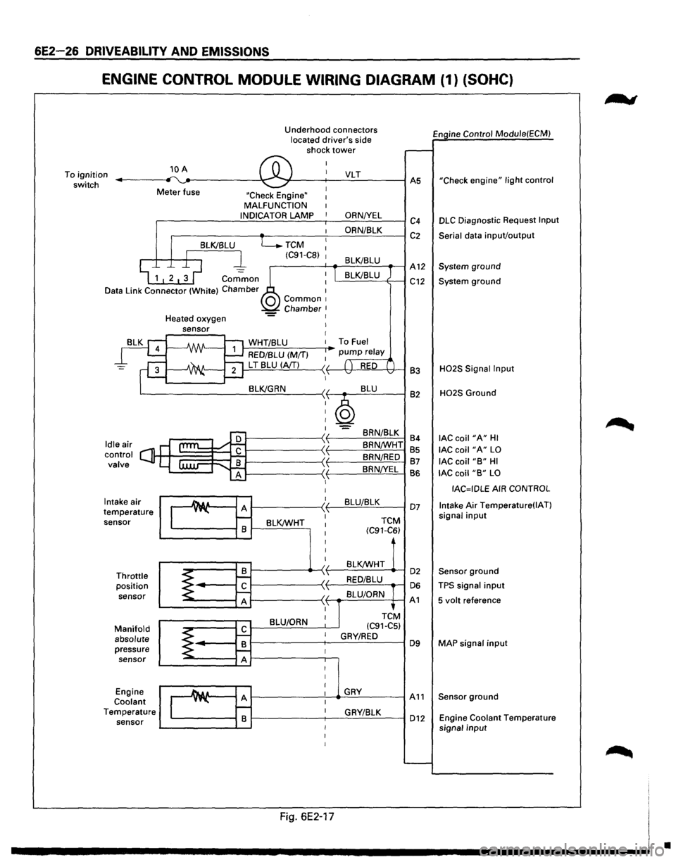
6E2-26 DRIVEABILITV AND EMISSIONS
ENGINE CONTROL MODULE WIRING DIAGRAM (1) (SOHC}
To ignition
switch 10 A
Meter fuse Underhood
connectors
located driver's side
shock tower
"Check Engine" MALFUNCTION
.-----------..:.:.1 N.:.:D:..:.IC=A~T~O:..:.R.:....=:.LA..::.M.:..::P:..___-,--___.:O:..:.R.:.:.N::.._IY.....:E:..:L=----1 c4
.------~~----~~O:..:R:..:N/~8~L=-=K--~ C 2
TCM
(C91-C8)
Engine Control Module(ECM)
"Check
engine" light control
DLC Diagnostic Request Input
Serial
data inpuVoutput
.--------f---+-....::...::;_;__=---_-1 A 12 System ground
Common
Data Link Connector (White) Chamber L.....::.=::....=..:=-=----+---1 C12 System ground
Intake air
temperature sensor
Throttle position
sensor
Manifold absolute pressure sensor
Engine
Coolant Temperature sensor Heated
oxygen
J-,.:..:W:.:..H.:..:T.:.:I8:..:L:.:U:......__ __ ....-To Fuel
RED/BLU (M/T)
1---=-'L T'-.!8~L:!:U'--l(.::::A/T!....!...!....) ---< f------lt+-~!,!..._'H---1 83
BRN/8LK
84
8RN/WHT 85
BRN/RED 87
8RN!YEL
BS
1---------~~~B~L~U~/8~L~K~--I 07
BLK/WHT
TCM
(C91-C6)
BLK/WHT 1------------4>---< t-----=~:..:.:..:_.:..:_ ....... -1 02
1-----------~ f----'-=-'-==--....-1 06
1-----------~ f--.-::..:=.=.:....=..c~-+--1 A 1
BLU/ORN
H02S Signal Input
H02S Ground
lAC coil "A" HI
lAC coil "A" LO
lAC coil "B" HI
lAC coil "B" LO
IAC=IDLE AIR CONTROL
Intake
Air Temperature(IAT)
signal input
Sensor ground
TPS signal input
5 volt reference
MAP
signal input
1---------'----...._.G:=.:..:.RY-=--------1 A 11 Sensor ground
1-------;---.:::G:..:R_;_YI:...::8:..:L::..:K:__---I 012 Engine Coolant Temperature
signal input
Fig. 6E2-17
•
Page 723 of 1928
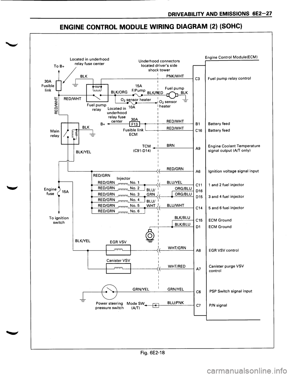
DRIVEABILITY AND EMISSIONS 6E2-27
ENGINE CONTROL MODULE WIRING DIAGRAM (2) (SOHC)
Located in underhood Engine Control
Module(ECM) Underhood connectors
To B+ relay fuse center located driver's side
/r BLK r----------s-ho-c-1-:-t-ow_:_::...:~.:..:K!Wc..:...:..:H:...:T.:..__---I C3 Fuel pump relay control
30A
Fusible
link
15A I F/P 1 Fuel pump BLK/ORG ~~
02 sensor heater 1 1 0 -2 sensor -10A 1 heater Fuel pump
BLK/YEL
relay Located in underhood relay fuse
center
B+ ------1
I
REO/WHT t---.-----t--:..:.::::..=.!...:...:..:..:...:_.:..._--1 B 1 Battery feed
REO/WHT
'-----t--..:.:..::-=:!....:c.:.:...:.-=-------1 C16 Battery feed
TCM BRN (C91-014) -_.:..._--=..:..:..:...:----1 A9 Engine Coolant Temperature signal output (A/T only)
L----~-----------~~-.:..:R.:::EO~/~G~R~N_:_--IA6 Ignition
voltage signal input
Engine
fuse 15A
To
ignition switch BLK/YEL
=
REO/GRN
REO/GRN
REO/GRN
REO/GRN
REO/GRN
REO/GRN
REO/GRN
ORG/BLU 016
ORG/BLU 015
L:...:..::..:-=---.....-:..:.:....:...!._{ L_B::..:L:..:U:c..IW:..:..:...:.HT_:__--l c " 14
BLK/BLU C15
,--.----<.._.:::B.:::LKI=B.::.LU=---1 01
GRN/YEL GRN/YEL
~--~~~~--~~~~--~C6
Power steering Mode SW--+*-f--=-8=-LU~/.:..P.:..:N~K:___---l pressure switch (A/T) C7
Fig. 6E2-18
1 and 2 fuel injector
3 and 4 fuel injector
5 and 6 fuel injector
ECM Ground
ECM Ground
EGR VSV control
Canister purge VSV
control
PSP Switch signal input
P/N signal
Page 724 of 1928
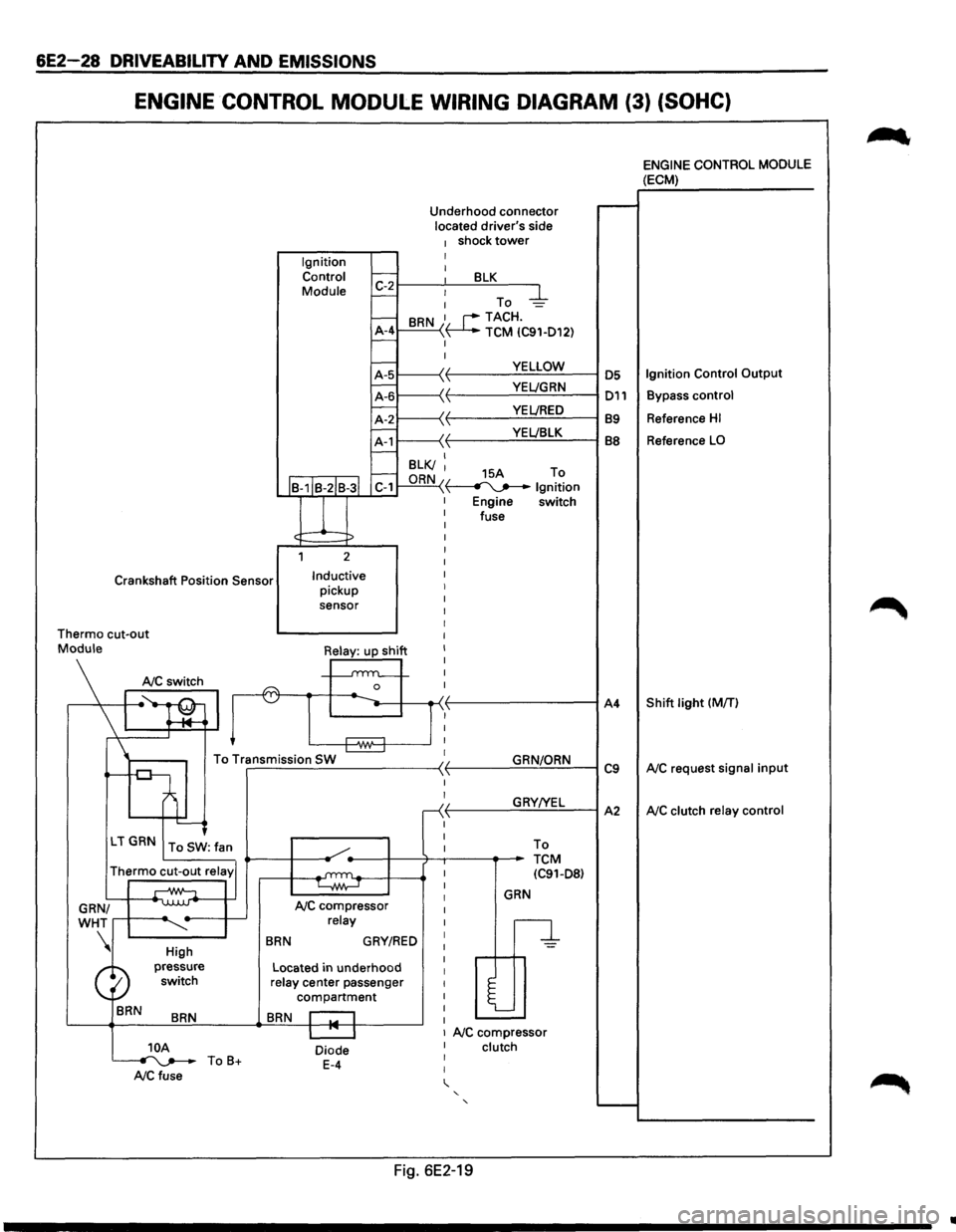
6E2-28 DRIVEABILITV AND EMISSIONS
ENGINE CONTROL MODULE WIRING DIAGRAM (3) (SOHC)
Ignition Control
Module Underhood
connector
located driver's side
1 shock tower I I 1:-2~--~~--~B~L~K~--~
- : To -4-
-BRN 1. r--TACH.
A-4 ~ TCM IC91-D12) -I
I
YELLOW
·~ YEL!GRN \ VEL/RED YEL!BLK
I--B-1IB-2IB-3l C-1
l
1 2
Crankshaft Position Sensor Inductive pickup
sensor I
I
I
I
Thermo cut-out I
I
I
I
I
n I
Mo\\I•Silj ~~
To Transmission SW ~ r-------------------~ -
'---<
LT GRN To SW: fan
Thermo cut-out relay'
GRN/
WHT
....--+-----~
BRN
High
pressure switch
BRN
NC compressor relay
BRN GRY/RED
Located in underhood relay center passenger
compartment
BRN r::-1
I
I
r
I
I
I
I
I
I
I
I
I
I
I
I
I
I
GRN/ORN
GRY!YEL To
TCM IC91-D8)
GRN
n
l
I I 1 NC compressor 10A ~ToB+ NCfuse
Diode E-4
I clutch I
I
' ' '
Fig. 6E2-19
A4
C9
A2
~
ENGINE CONTROL MODULE (ECM)
Reference HI
Reference LO
Shift light (MfT)
NC request signal input
NC clutch relay control
..
Page 725 of 1928
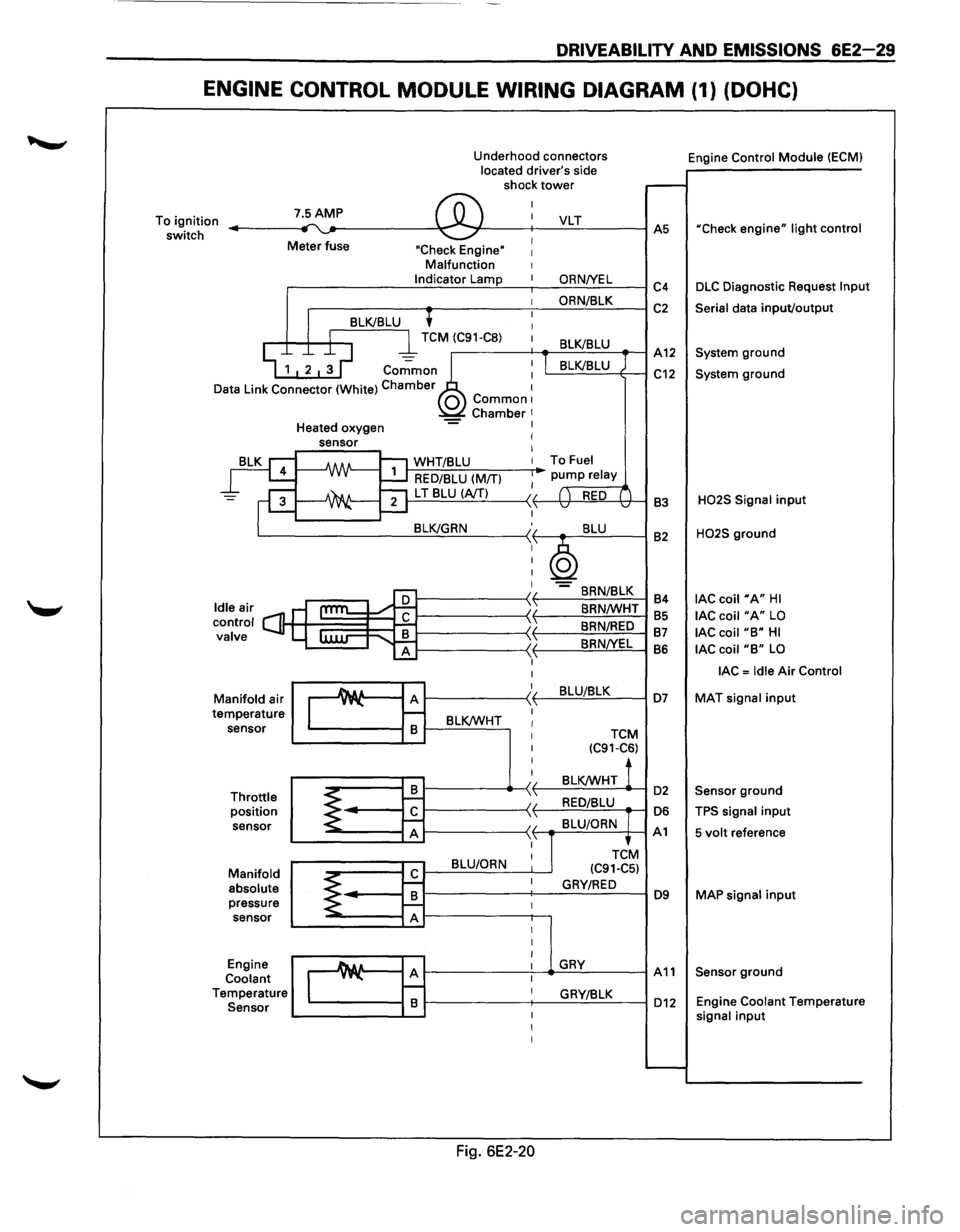
DRIVEABILITY AND EMISSIONS 6E2-29
ENGINE CONTROL MODULE WIRING DIAGRAM (1) (DOHC)
Underhood connectors
located driver's side
shock
tower
To ignition
switch 7.5AMP ,.... ~ ®
I
I
Meter fuse I "Check Engine" I Malfunction I Indicator Lamp I
I
'
I 8LK/8LU I
D
I l TCM (C91-C8) 1
~ 1 2 ~ ~ co.;;mo~~ : ata Link Connector (White) Chamber 1 0 Common1 Chamber 1 Heated oxygen -= I
rg
=F
leair s ontrol C] alve
ld c v
M
te anifold
air
mperature sensor
Throttle position sensor
Manifold absolute pressure sensor
Engine
Coolant
T emperature
Sensor
sensor I
I
-A/IN-1:'1 WHT/8LU I
~ RED/8LU (M/TI I
~ ""21 L T 8LU (A/TI II ....::....1 ,1,
8LK/GRN :,
I
I
I
I
cam l:
I
I
Au A )I y"-\1 r--
8 8LK/WHT I I
I
I
I
8 ~ 1--II
~ r£ \ 'I A ,1,
8LU/ORN I
r£ ~ I
8 ~ f--I A I
I
I
_A& a A I y"-I r--I 8 I
I
I
Fig. 6E2-20
VLT
ORNNEL
ORN/8LK
8LK/8LU
I 8LK/8LU
To Fuel
pump relay
( ) RED ( v v
8LU
~ -8RN/8LK
8RN/WHT
8RN/RED
8RNNEL
8LU/8LK
TCM (C91-C6)
8LK/WHT !
RED/8LU
8LU/ORN
TCtM
(C91-C5)
GRY/RED
GRY
GRY/8LK Engine
Control
Module (ECMI
.-----
AS "Check engine" light control
C4 DLC Diagnostic Request lnpu
C2 Serial data input/output
A12 System ground
C12 System ground
83
H02S Signal input
82 H02S ground
84
lAC coil "A" HI
85 lAC coil "A" LO
87 lAC coil "8" HI
86 lAC coil "8" LO
lAC = Idle Air Control
D7 MAT signal input
D2 Sensor ground
D6 TPS signal input
A1 5 volt reference
D9 MAP signal input
A11 Sensor ground
D12 Engine Coolant Temperatur e signal input
......__