stop start ISUZU TROOPER 1995 Manual PDF
[x] Cancel search | Manufacturer: ISUZU, Model Year: 1995, Model line: TROOPER, Model: ISUZU TROOPER 1995Pages: 1928
Page 1432 of 1928
8-242 CHASSIS ELECTRICAL
STARTER SWITCH
Refer to "START AND CHARGING" of this section.
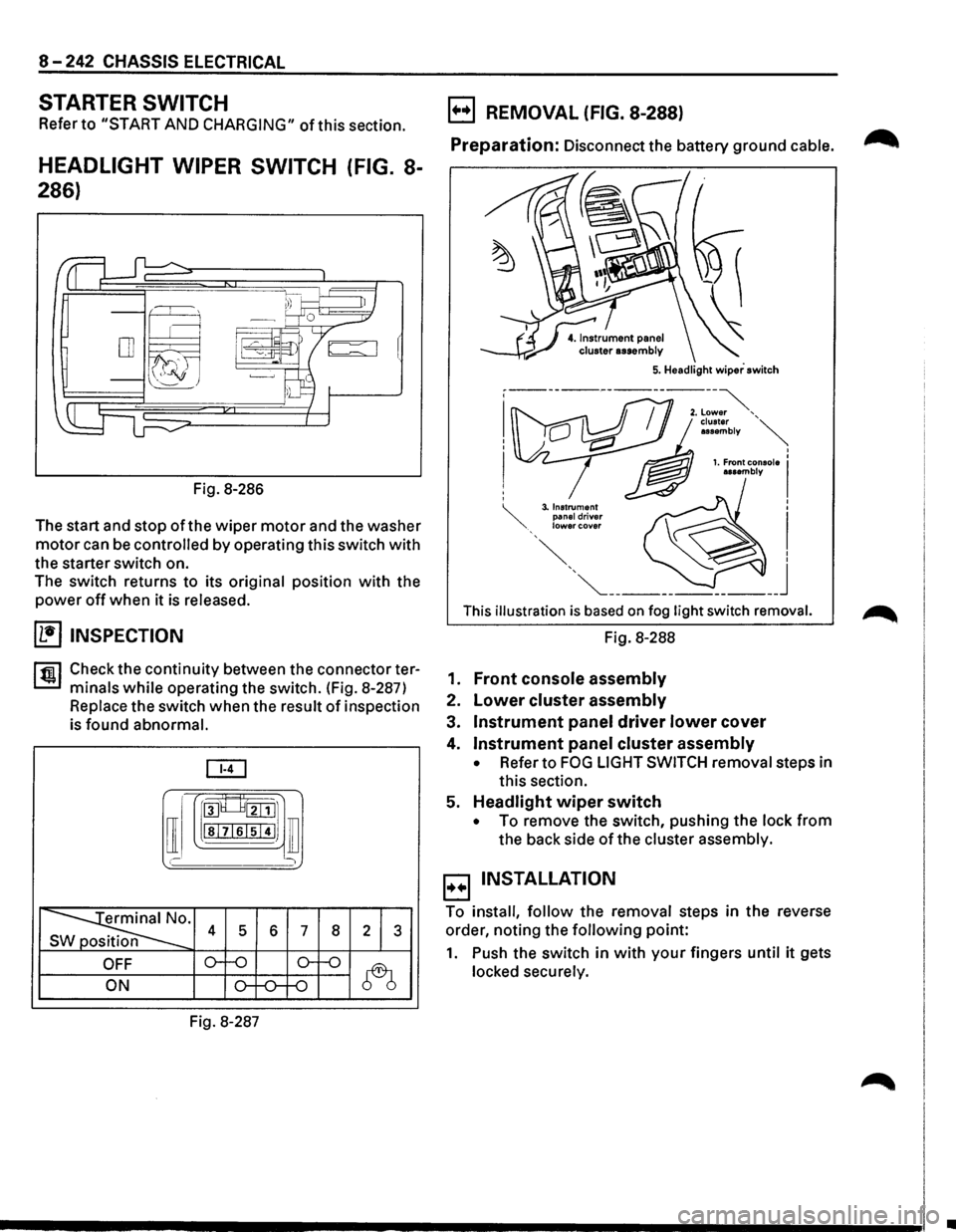
HEADLIGHT WIPER SWITCH (FIG. 8-
286)
Fig. 8-286
The start and stop
of the wiper motor and the washer
motor can be controlled by operating this switch with
the starter switch on.
The switch returns to its
original position with the
power off when it is released.
(1!] INSPECTION
rfiil Check the continuity between the connector ter
L:::.I minals while operating the switch. (Fig. 8-287)
Replace the switch when the result of inspection
is
found abnormal.
[ill
[I
roo8___8tillJ1
lsl7lslsi4IJ ill
' )
~· s 4 5 6 7 8 2 1 3
OFF o--o o-f-o
~ ON o-f-0--f-0
Fig. 8-287
B REMOVAL (FIG. 8-288)
Preparation: Disconnect the battery ground cable. ~
This illustration is based on fog light switch removal.
Fig. 8-288
1.
Front console assembly
2. Lower cluster assembly
3. Instrument panel driver lower cover
4. Instrument panel cluster assembly
• Refer to FOG LIGHT SWITCH removal steps in
this section.
5.
Headlight wiper switch
• To remove the switch, pushing the lock from
the back side of the cluster assembly.
B INSTALLATION
To install, follow the removal steps in the reverse
order, noting the
following point:
1. Push the switch in with your fingers until it gets
locked securely.
•
Page 1466 of 1928
8-276 CHASSIS ELECTRICAL
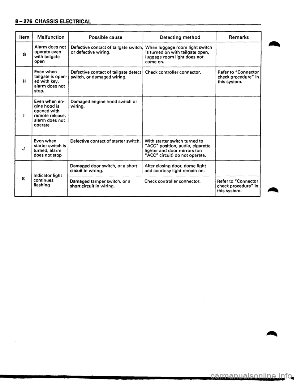
Item Malfunction
Possible cause
Detecting method Remarks
Alarm
does not
Defective contact of tailgate switch When luggage room light switch
G operate even or defective wiring. is turned on with tailgate open, with tailgate
luggage room light does not open
come on.
Even when
Defective contact
of tailgate detect Check controller connector. Refer to "Connector tailgate is open-
switch, or damaged wiring.
check procedure" in H ed with key, this system.
alarm does not
stop.
Even when en-
Damaged engine hood switch or gine hood is wiring.
opened with
I remote release,
alarm does not
operate
Even when
Defective contact
of starter switch. With starter switch turned to
J starter switch is II ACC" position, audio, cigarette
turned, alarm
lighter and door mirrors (on
does not stop
II ACC" circuit) do not operate.
Damaged
door switch, or a short After closing door, dome light
circuit in wiring. and courtesy light remain on.
K Indicator light
continues Damaged tamper switch, or a
Check controller connector. Refer to "Connector flashing
short circuit in wiring. check
procedure" in
this system.
..
Page 1467 of 1928
------------- -
CHASSIS ELECTRICAL 8-279
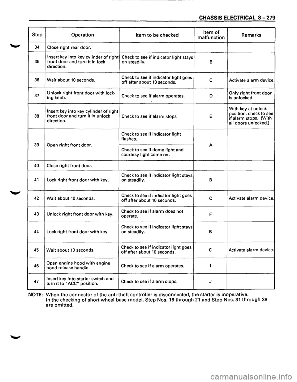
Step Operation Item to be checked Item of Remarks
malfunction
34 Close right rear door.
Insert key into key cylinder of right
Check to see if indicator light stays 35 front door and turn it in lock on steadily. B direction.
36 Wait about 10 seconds. Check
to see if indicator light goes c Activate alarm device. off after about 10 seconds.
37 Unlock right front door with lock-Check to see if alarm operates. D Only right front door ing knob.
is unlocked.
Insert
key into key cylinder of right With
key at unlock
position, check to see 38 front door and turn it in unlock Check to see if alarm stops E if alarm stops. (With
direction.
all doors unlocked.)
Check to see if indicator light flashes.
39 Open right front door.
A
Check to
see if dome light and
courtesy light come on.
40 Close right front door.
Check to
see if indicator light stays 41 Lock right front door with key.
on steadily. B
42 Wait about 10 seconds. Check
to see if indicator light goes c Activate alarm device. off after about 10 seconds.
43 Unlock right front door with key. Check
to see if alarm does not F operate.
Check to
see if indicator light stays 44 Lock right front door with key.
on steadily. B
45 Wait about 10 seconds. Check
to see if indicator light goes c Activate alarm device. off after about 10 seconds.
46 Open engine hood with engine
Check to see if alarm operates. I hood release handle.
47 Insert key into starter switch and
Check to see if alarm stops. J turn it to "ACC" position.
NOTE: When the connector of the anti-theft controller is disconnected, the starter is inoperative.
In the checking of short wheel base model, Step Nos. 16 through 21 and Step Nos. 31 through 36
are omitted.
Page 1469 of 1928
CHASSIS ELECTRICAL 8 ~ 277
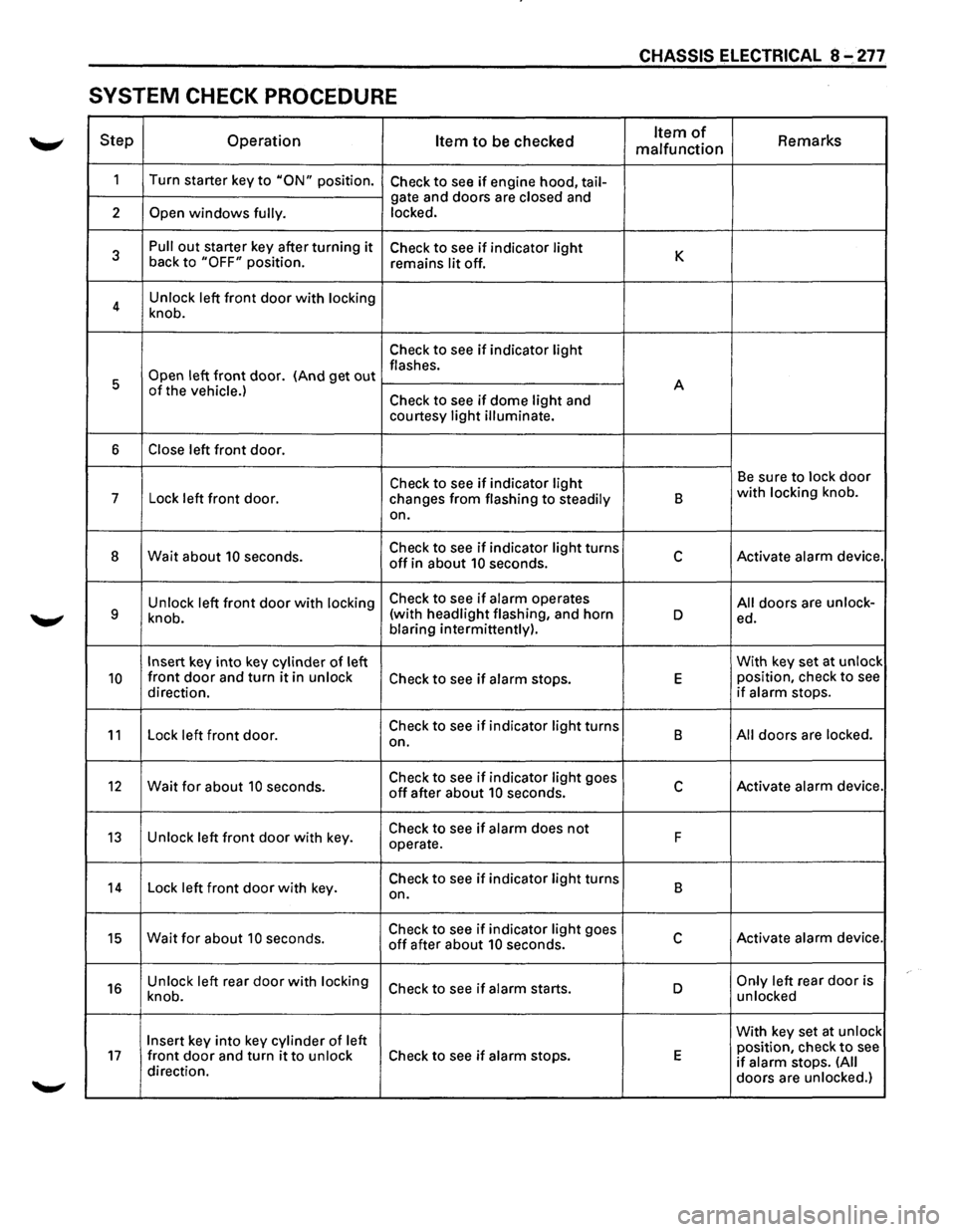
SYSTEM CHECK PROCEDURE
Step Operation Item to be checked Item of Remarks malfunction
1
Turn starter key to "ON" position. Check to see if engine hood, tail-
gate and doors are closed and
2
Open windows fully. locked.
3
Pull out starter key after turning it Check to see if indicator light K back to "OFF" position.
remains lit off.
4 Unlock
left
front door with locking
knob.
Check to see if indicator light
Open left front door. (And get out flashes.
5 A
of the vehicle.) Check to see if dome light and
courtesy light illuminate.
6 Close left front door.
Check to see if indicator light Be sure to lock door
7
Lock left front door.
changes from flashing to steadily B with locking knob.
on.
8 Wait about 10 seconds. Check to see if indicator light turns c Activate alarm device. off in about 10 seconds.
Unlock left
front door with locking Check to see if alarm operates All doors are unlock-9 knob. (with
headlight flashing, and horn D ed.
blaring intermittently).
Insert key into key cylinder of left With
key set at unlock
10 front door and turn it in unlock Check to see if alarm stops. E position, check to see
direction. if alarm stops.
11 Lock left front door. Check to see if indicator light turns
B All doors are locked.
on.
12 Wait for about 10 seconds. Check to see if indicator light goes c Activate alarm device. off after about 10 seconds.
13 Unlock left front door with key. Check to see if alarm does not F
operate.
14 Lock left front door with key. Check to see if indicator light turns
B
on.
15 Wait for about 10 seconds. Check to see if indicator light goes c Activate alarm device. off after about 10 seconds.
16 Unlock left rear door with locking Check to see if alarm starts. D Only left rear door is
knob. unlocked
Insert key
into key cylinder of left With
key set at unlock
position, check to see 17 front door and turn it to unlock Check to see if alarm stops. E if alarm stops. (All direction.
doors are unlocked.)
Page 1532 of 1928
8-340 CHASSIS ELECTRICAL
HEATER AND AIR CONDITIONING
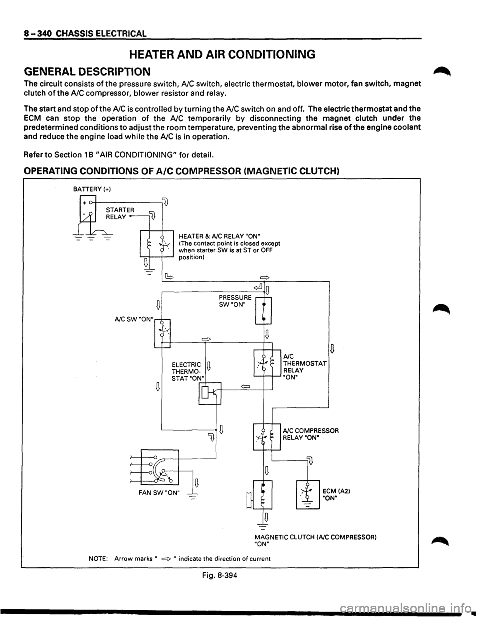
GENERAL DESCRIPTION
The circuit consists of the pressure switch, NC switch, electric thermostat, blower motor, fan switch, magnet
clutch of the NC compressor, blower resistor and relay.
The start and stop of the NC is controlled by turning the NC switch on and off. The electric thermostat and the
ECM can stop the operation of the NC temporarily by disconnecting the magnet clutch under the
predetermined conditions
to adjust the room temperature, preventing the abnormal rise of the engine coolant
and reduce the engine load while the NC is in operation.
Refer
to Section 18 "AIR CONDITIONING" for detail.
OPERATING CONDITIONS OF A/C COMPRESSOR (MAGNETIC CLUTCH)
BATIERY(+)
--
~
A/C SW "ON"
~
HEATER & A/C RELAY "ON"
(The contact point is closed except
when starter SW is at ST or OFF position)
(S =:>
¢:!]
PRESSURE D
SW"ON"
¢:::l
~ FAN SW"ON"
u A/C THERMOSTAT
RELAY
"ON"
A/C COMPRESSOR
RELAY"ON"
ECM IA2l "ON"
MAGNETIC
CLUTCH lAIC COMPRESSOR)
"ON"
NOTE:
Arrow marks" =:> " indicate the direction of current
Fig. 8-394
~
1111
Page 1536 of 1928
8-346 CHASSIS ELECTRICAL
SUN ROOF
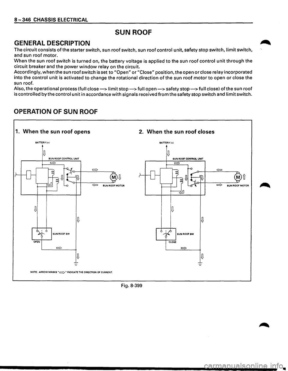
GENERAL DESCRIPTION
The circuit consists of the starter switch, sun roof switch, sun roof control unit, safety stop switch, limit switch,
and sun roof motor.
When the sun
roof switch is turned on, the battery voltage is applied to the sun roof control unit through the
circuit breaker and the power
window relay on the circuit.
Accordingly,
when the sun roof switch is set to "Open" or "Close" position, the open or close relay incorporated
into the control
unit is activated to change the rotational direction of the sun roof motor to open or close the
sun roof.
Also, the operational process (full close-> limit stop-> full open-> safety stop-> full close) ofthe sun roof
is
controlled by the control unit in accordance with signals received from the safety stop switch and limit switch.
OPERATION OF SUN ROOF
1. When the sun roof opens 2. When the sun roof closes
BATTERY(+!
BATTERY(+)
D D SUN ROOF CONTROL UNIT SUN ROO!' CONTIIOI. UNIT
D D
D
D
SUNROOF SW SUNROOFSW
D D
NOTE: ARROW MARKS • =:> • INDICATE THE DIRECTlON 01' CURRENT.
Fig. 8-399
Ill
Page 1752 of 1928
9J-128 Supplemental Restraint System
12. Remove steering column cover.
13. Disconnect the wiring harness connectors ~
located base of steering column.
14. Remove the combination switch assembly with
SRScoil.
NOTE: SRS
coil is a part of combination switch
assembly, which
cannot be replaced individually.
Therefore, be sure not to remove the
SRS coil from the
combination switch assembly.
INSTALLATION
1. Install the combination switch assembly with
SRScoil.
2. Connect the wiring harness connector located In
base of steering column.
3. Turn the SRS coil clockwise to full, return about
3 turns and align the neutral mark.
CAUTION: WHEN TURNING THE SRS COIL
CLOCKWISE TO FULL, STOP TURNING IF
RESISTANCE IS FELT. FORCED FURTHER
TURNING MAY CAUSE DAMAGE TO THE CABLE IN
THE SRS COIL.
4. Install steering column cover.
CAUTION: WHEN INSTALLING THE STEERING
COLUMN COVER, BE SURE TO WIRE (THROUGH ~
EACH HARNESS) AS ILLUSTRATED SO THAT THE
HARNESSES OF STARTER SWITCH,COMBINATION
SWITCH
AND SRS COIL MAY NOT CATCH WIRING.
5. Install the steering wheel and align the setting
marks.
6. Tighten the steering fixing nut to the specified
torque.
Torque : 34N·m(25 lb·ft.).
7. Connect horn lead connector.
8. Connect inflator module to 2-way yellow wiring
harness connector.
9. Install inflator module into steering wheel and
torque fasteners.
NOTE: Always replace inflator module {Air Bag)
fasteners with new fasteners. Never reuse old fasteners.
Torque: 8N·m(69 lb·ln.)
10. Install the steering lower cover and engine hood
opening lever.
11. Install front console assembly and connect the
wiring harness connector.
12. Install the transmission knob{for M/T) and
transfer control knob. ~
13. Enable the SRS (Refer to "Enabling the SRS" in
this section.).
•
Page 1755 of 1928
1 o. Connect the wiring harness connector located
base of steering column.
11. Turn the SRS coil clockwise to full, return about
3 turns and align the neutral mark.
CAUTION: WHEN TURNING THE SRS COIL
CLOCKWISE TO FULL, STOP TURNING IF
RESISTANCE IS FELT. FORCED FURTHER
TURNING MAY CAUSE DAMAGE TO THE CABLE IN
THE SRS COIL.
12. Install steering column cover.
CAUTION: WHEN INSTALLING THE STEERING
COLUMN COVER,
BE SURE TO WIRE {THROUGH
EACH HARNESS) AS ILLUSTRATED SO THAT THE
HARNESSES OF STARTER SWITCH,COMBINATION
SWITCH
AND SRS COIL MAY NOT CATCH WIRING.
13. Install the steering wheel and align the setting
marks.
14. Tighten the steering fixing nut to the specified
torque.
Torque: 34N·m(25 lb·ft.).
15. Connect horn lead connecor.
16. Connect inflator module to
2-way yellow wiring
harness connector.
17.
Install inflator module into steering wheel and
torque fasteners.
Torque: 8N·m(69 lb-in.)
18. Install the steering lower cover and engine hood
opening lever.
19.
Install front console assembly and connect the
wiring harness connector.
20.
Install the transmission knob(for M/T) and
transfer control knob.
21. Enable the
SRS (Refer to "Enabling the SRS" in
this section.).
Supplemental Restraint System 9J-131