stop start ISUZU TROOPER 1995 Repair Manual
[x] Cancel search | Manufacturer: ISUZU, Model Year: 1995, Model line: TROOPER, Model: ISUZU TROOPER 1995Pages: 1928
Page 1377 of 1928
::!! (Q 00 I ....., w ..,..
(
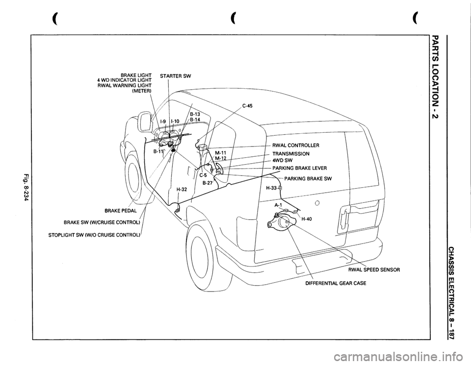
BRAKE
LIGHT
STARTER
SW
4 WD
INDICATOR
LIGHT
RWAL
WARNING
LIGHT (METER)
BRAKE
SW
(W/CRUISE
CONTROL)
STOPLIGHT
SW
(W/0
CRUISE
CONTROL)
(
C-45
JfJI:
/
I
RWAL
CONTROLLER
TRANSMISSION
4WDSW
PARKING
BRAKE
SW
(
;g ::JJ -1 en .... 0 0 ~ -0 2 N
n :I: l> en en c;; m rm n -t :a g reo I ~ co .....
Page 1390 of 1928
8 -200 CHASSIS ELECTRIC'Al
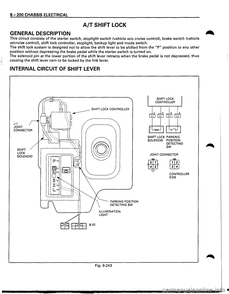
A/T SHIFT LOCK
GENERAL DESCRIPTION
This circuit consists of the starter switch, stoplight switch (vehicle w/o cruise control), brake switch (vehicle
w/cruise control),
shift lock controller, stoplight, backup light and mode switch.
The shift lock system is designed not
to allow the shift lever to be shifted from the "P" position to any other
position
without depressing the brake pedal while the starter switch is turned on.
The solenoid pin at the
lower portion of the shift lever retracts when the brake pedal is not depressed, thus
causing the shift lever cam
to be locked by the link lever.
INTERNAL CIRCUIT OF SHIFT LEVER
J-1 JOINT CONNECTOR
SHIFT
LOCK
SOLENOID
B-32
PARKING POSITION
DETECTING SW
ILLUMINATION LIGHT
Fig. 8-243
SHIFT LOCK PARKING
SOLENOID POSITION
DETECTING
sw
JOINT CONNECTOR
CONTROLLER
SIDE
•
Page 1391 of 1928

"T1 ce· 00 I N ~ ~
(
BRAKE
SW
(W/CRUISE
CONTROL)
STOPLIGHT
SW
(W/0
CRUISE CONTROL)
SHIFT
LEVER
" ""'
SHIFT
LOCK
CONTROLLER
""''
RELAY
& FUSE
BOX
(FL-1,
FL-2)
(
STARTERSW
BRAKE
PEDAL
STOP
LIGHT
(LH)
\R-7 "-TRAILER
HARNESS
CONNECTOR
(H-44)
(
;g ~ r-0 0 ~ 5 z
0 :J: ~ en u; m rm ~ :a g reo I N 0 ....
Page 1394 of 1928
·;.
8 -204 CHASSIS ELECTRICAL
STARTER SWITCH
Refer to "START AND CHARGING" in this section.
STOPLIGHT
STOPLIGHT SWITCH
BRAKE SWITCH
Refer to "STOPLIGHT AND REAR DEFOGGER" in
,c, this section.
SHIFT LOCK CONTROLLER
Refer to the shift lock controller in Section 7 A
"AUTOMATIC TRANSMISSION."
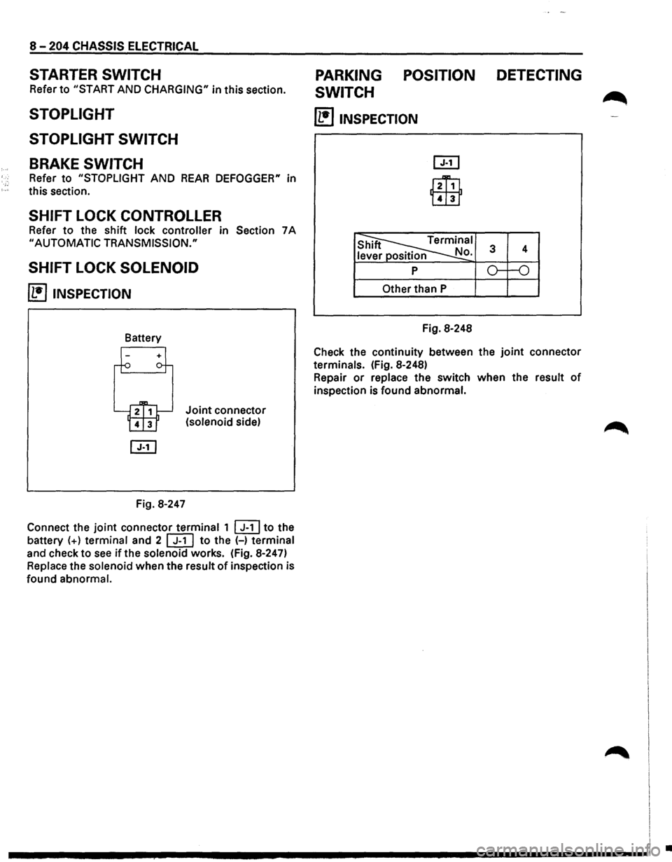
SHIFT LOCK SOLENOID
~ INSPECTION
Fig. 8-247
Joint connector
(solenoid side)
Connect the
joint connector terminal 1 ~to the
battery
(+) terminal and 2 [ill to the (-) terminal
and check to
see if the solenoid works. (Fig. 8-247)
Replace the solenoid when the result
of inspection is
found abnormal.
PARKING POSITION DETECTING
SWITCH
~
(1!]1NSPECTION
l2Ti1
Lill1
Other than P
Fig. 8-248
Check the continuity between the
joint connector
terminals. (Fig. 8-248)
Repair
or replace the switch when the result of
inspection is found abnormal.
I
I I
.............. ~ ................................ -----------------1 .
Page 1395 of 1928
CHASSIS ELECTR1CAL 8-205
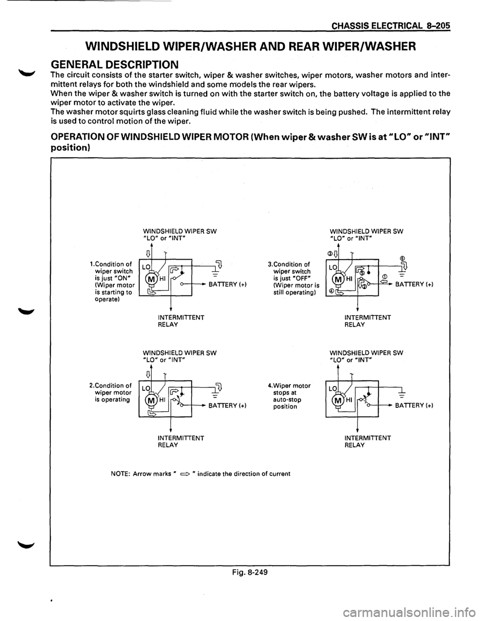
WINDSHIELD WIPER/WASHER AND REAR WIPER/WASHER
GENERAL DESCRIPTION
~ The circuit consists of the starter switch, wiper & washer switches, wiper motors, washer motors and inter
mittent relays for both the windshield and some models the rear wipers.
When the
wiper & washer switch is turned on with the starter switch on, the battery voltage is applied to the
wiper motor to activate the wiper.
The washer
motor squirts glass cleaning fluid while the washer switch is being pushed. The intermittent relay
is used
to control motion of the wiper.
OPERATION OF WINDSHIELD WIPER MOTOR (When wiper & washer SW is at "LO" or ''I NT"
position)
1.Condition of wiper switch is just "ON" (Wiper motor is starting to operate)
2.Condition
of wiper motor is operating
WINDSHIELD WIPER SW "LO" or "INT"
o--+--BATTERY(+)
INTERMITTENT RELAY
WINDSHIELD WIPER SW "LO" or "INT"
INTERMITTENT RELAY
3.Condition of
wiper switch
is just "OFF" (Wiper motor is still operating)
4.Wiper
motor stops at auto-stop position
NOTE: Arrow marks " =:> " indicate the direction of current
Fig. 8-249
WINDSHIELD WIPER SW "LO" or "INT"
INTERMITTENT RELAY
WINDSHIELD WIPER SW "LO" or "INT"
o--+--BATTERY(+)
INTERMITTENT RELAY
Page 1405 of 1928
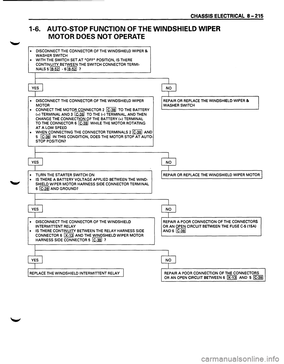
CHASSIS ELECTRICAL 8-215
1-6. AUTO-STOP FUNCTION OF THE WINDSHIELD WIPER
MOTOR DOES NOT
OPERATE
• DISCONNECT THE CONNECTOR OF THE WINDSHIELD WIPER & WASHER SWITCH
• WITH THE SWITCH SET AT HOFFH POSITION, IS THERE
CONTINUITY BETWEEN THE SWITCH CONNECTOR TERMI-
NALS5~ -6~ 7
I
I I
YES I NO I
I I
• DISCONNECT THE CONNECTOR OF THE WINDSHIELD WIPER REPAIR OR REPLACE THE WINDSHIELD WIPER & MOTOR WASHER SWITCH
• CONNECT THE MOTOR CONNECTOR 2 I C-381 TO THE BATTERY (+) TERMINAL AND 3 ~ TO THE H TERMINAL, AND THEN CHANGE THE CONNECTION OF THE BATTERY(+) TERMINAL TO THE CONNECTOR 6 I C-381 WHILE THE MOTOR ROTATING AT A LOW SPEED
• WHEN CONNECTING THE CONNECTOR TERMINALS 2IC-38I AND
5
~ IN THIS CONDITION, DOES THE MOTOR STOP AT AUTO-STOP POSITION?
l
I I
YES I NO I
I I
• TURN THE STARTER SWITCH ON REPAIR OR REPLACE THE WINDSHIELD WIPER MOTOR
• IS THERE A BATTERY VOLTAGE APPLIED BETWEEN THE WIND-SHIELD WIPER MOTOR HARNESS SIDE CONNECTOR TERMINAL
6 ~AND GROUND?
l
I I
YES I NO I
I I
• DISCONNECT THE CONNECTOR OF THE WINDSHIELD REPAIR A POOR CONNECTION OF THE CONNECTORS INTERMITTENT RELAY OR AN OPEN CIRCUIT BETWEEN THE FUSE C-5 (15A)
• IS THERE CONTINUITY BETWEEN THE RELAY HARNESS SIDE AND 6 IC-381 CONNECTOR 6 I X-131 AND THE WINDSHIELD WIPER MOTOR
HARNESS SIDE CONNECTOR 5 ~ 7
l
I I
YES I NO I
I I
REPLACE THE WINDSHIELD INTERMITTENT RELAY I REPAIR A POOR CONNECTION OF THE CONNECTORS I OR AN OPEN CIRCUIT BETWEEN 6 IX-131 AND 5 IC-381
Page 1409 of 1928
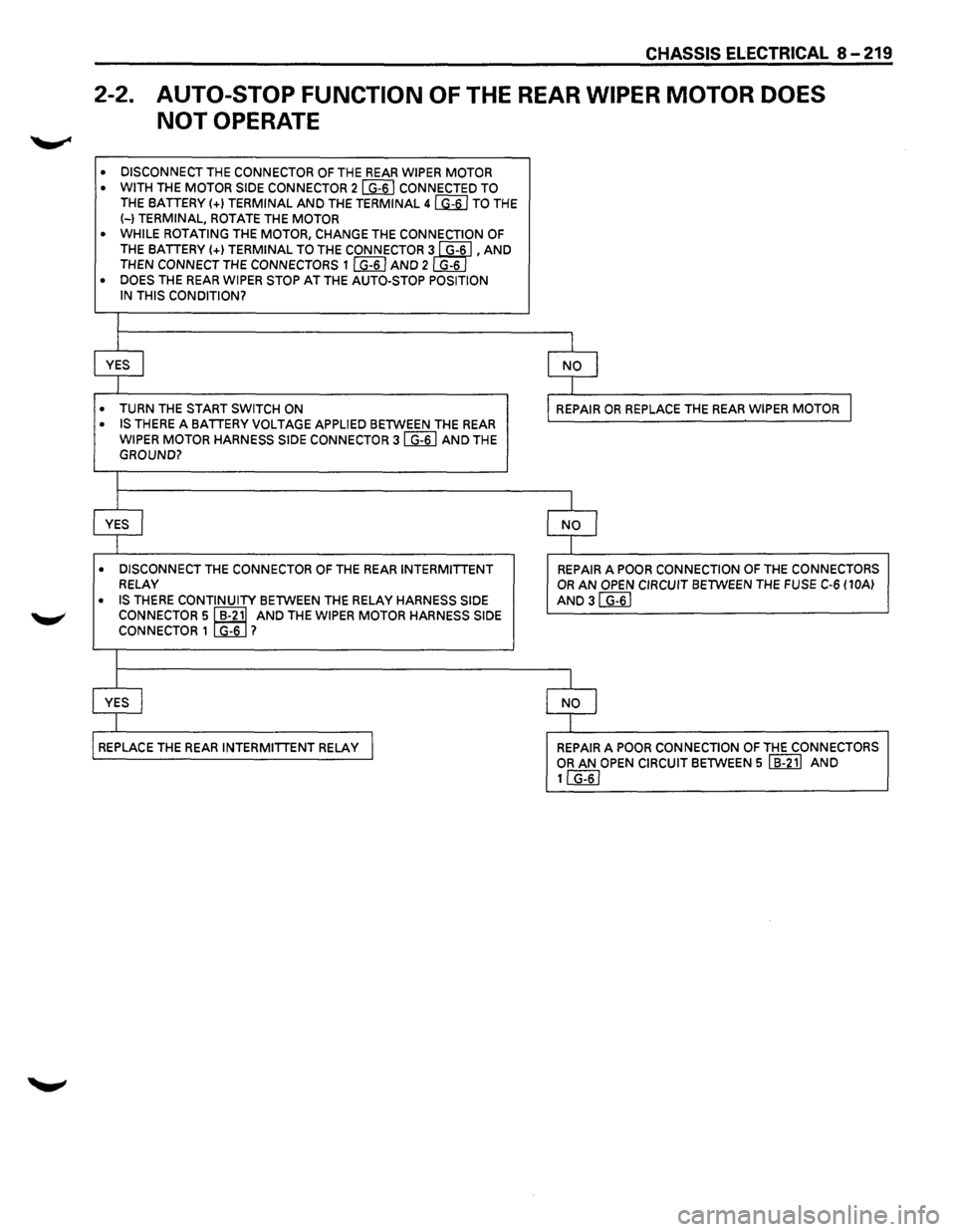
CHASSIS ELECTRICAL 8-219
2-2. AUTO-STOP FUNCTION OF THE REAR WIPER MOTOR DOES
NOT OPERATE
• DISCONNECT THE CONNECTOR OF THE REAR WIPER MOTOR
• WITH THE MOTOR SIDE CONNECTOR 2 ~ CONNECTED TO THE BATTERY(+) TERMINAL AND THE TERMINAL 4 ~TO THE (-)TERMINAL, ROTATE THE MOTOR
• WHILE ROTATING THE MOTOR, CHANGE THE CONNECTION OF
THE BATTERY(+) TERMINAL TO THE CONNECTOR 3~ , AND THEN CONNECT THE CONNECTORS 1 I G-6 I AND 2 G-6
• DOES THE REAR WIPER STOP AT THE AUTO-STOP POSITION
IN THIS CONDITION?
I
I I
YES J NO I
l I
• TURN THE START SWITCH ON
REPAIR OR REPLACE THE REAR WIPER MOTOR I
• IS THERE A BATTERY VOLTAGE APPLIED BETWEEN THE REAR
WIPER MOTOR HARNESS SIDE CONNECTOR 31 G-61 AND THE
GROUND?
I
I
I
YES I NO I
I I
• DISCONNECT THE CONNECTOR OF THE REAR INTERMITTENT REPAIR A POOR CONNECTION OF THE CONNECTORS RELAY OR AN OPEN CIRCUIT BETWEEN THE FUSE C-6 (10Al
• IS THERE CONTINUITY BETWEEN THE RELAY HARNESS SIDE AND 31 G-61 CONNECTOR 51B-211 AND THE WIPER MOTOR HARNESS SIDE
CONNECTOR 1 G-6 7
I
I
I
YES
I NO I
I I
REPLACE THE REAR INTERMITTENT RELAY I REPAIR A POOR CONNECTION OF THE CONNECTORS
OR AN OPEN CIRCUIT BETWEEN 5 IB-211 AND
11 G-61
Page 1416 of 1928
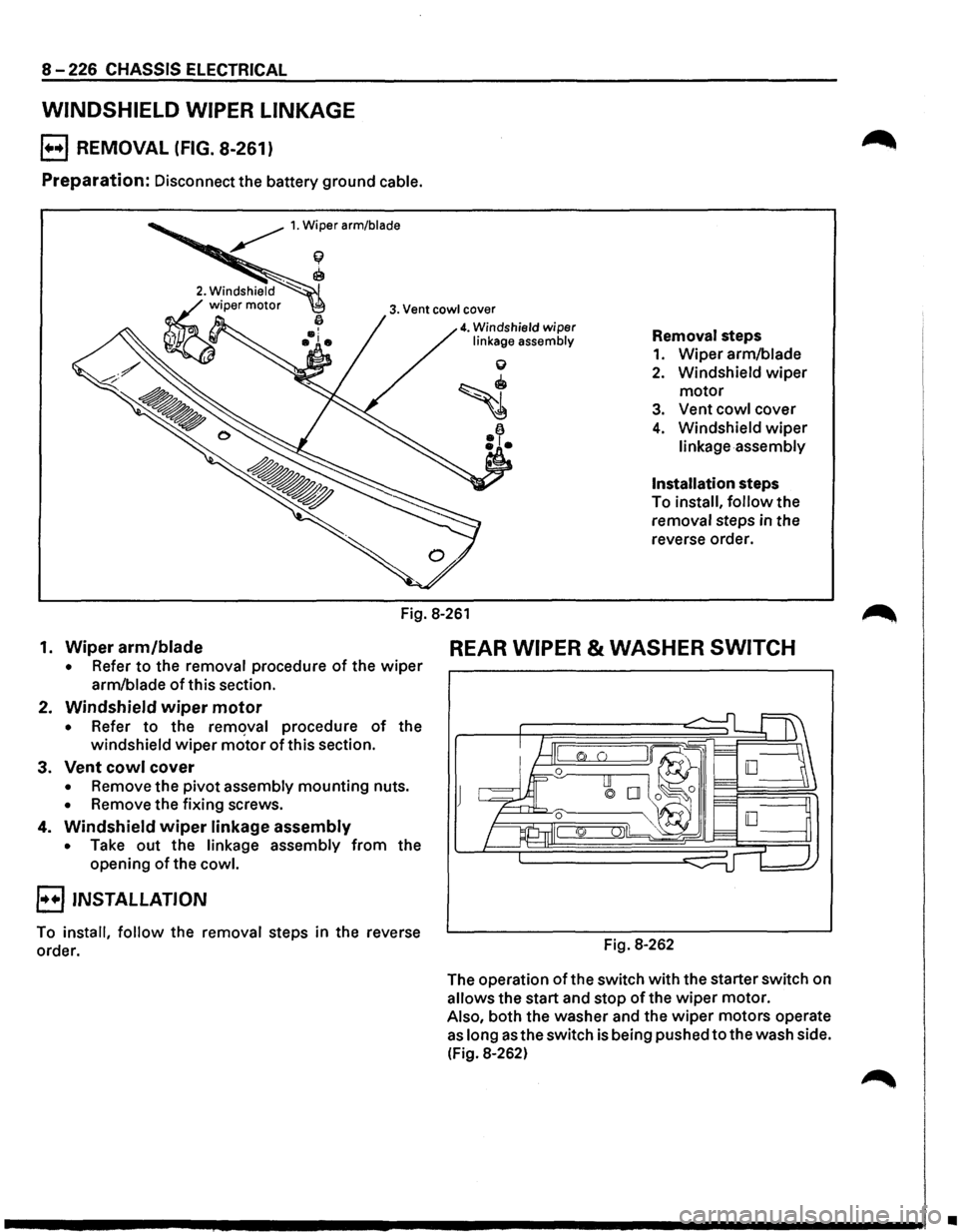
8-226 CHASSIS ELECTRICAL
WINDSHIELD WIPER LINKAGE
B REMOVAL (FIG. 8-261)
Preparation: Disconnect the battery ground cable.
~ 1. Wiper arm/blade
f(
~
3. Vent cowl cover
4. Windshield wiper linkage assembly Removal steps
1. Wiper arm/blade
2. Windshield wiper
motor
3. Vent cowl cover
4. Windshield wiper
linkage assembly
Installation steps
To install,
follow the
removal steps in the
reverse order.
Fig.
8-261
1. Wiper arm/blade REAR WIPER & WASHER SWITCH
• Refer to the removal procedure of the wiper
arm/blade ofthis section.
2. Windshield wiper motor
• Refer to the remqval procedure of the
windshield
wiper motor of this section.
3. Vent cowl cover
• Remove the pivot assembly mounting nuts.
• Remove the fixing screws.
4. Windshield wiper linkage assembly
• Take out the linkage assembly from the
opening
of the cowl.
B INSTALLATION
To install, follow the removal steps in the reverse
order. Fig. 8-262
The
operation of the switch with the starter switch on
allows the start and stop
of the wiper motor.
Also, both the washer and the
wiper motors operate
as long as the switch is being pushed to the wash side.
(Fig.
8-262)
•
Page 1422 of 1928
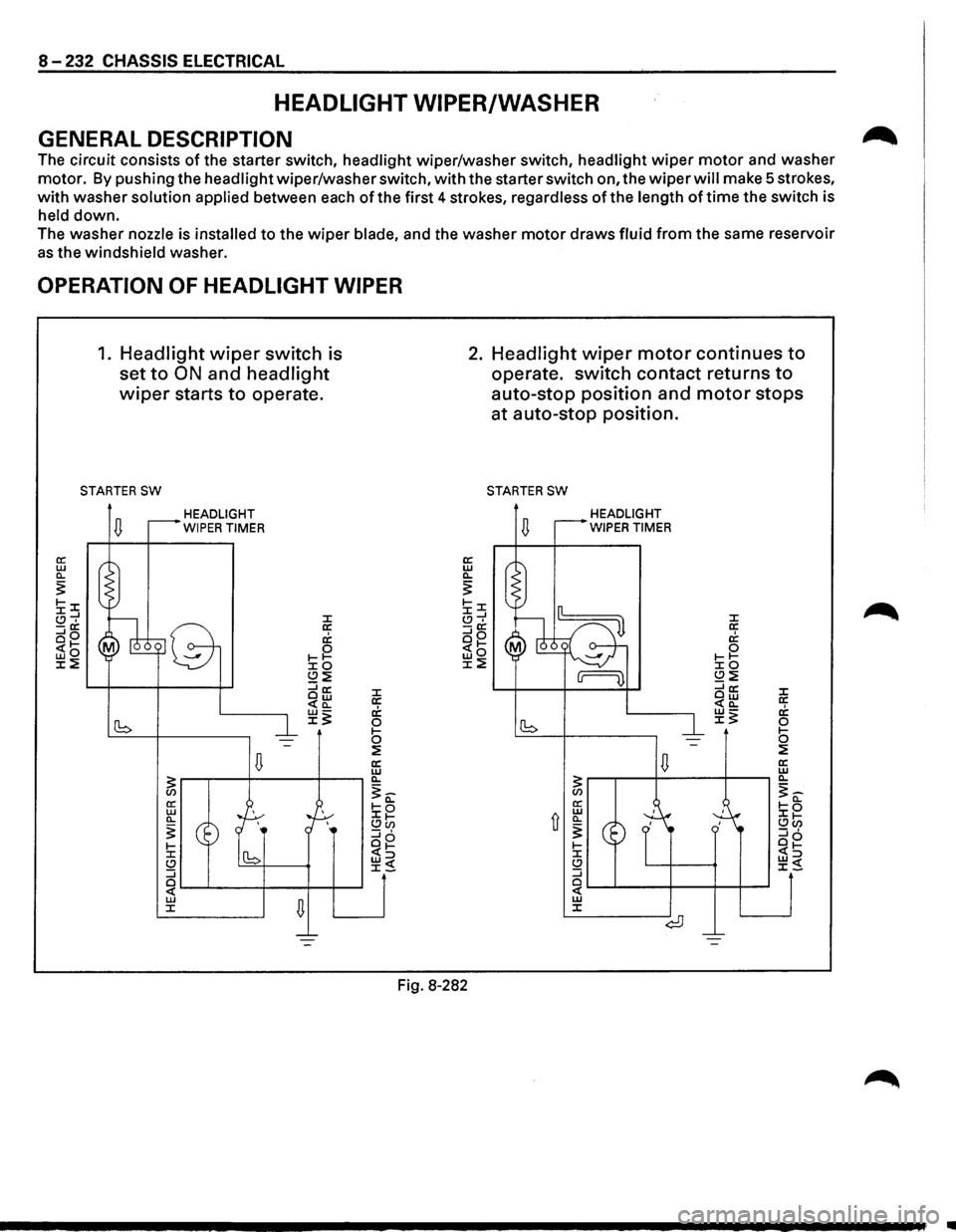
8 -232 CHASSIS ELECTRICAL
HEADLIGHT WIPER/WASHER
GENERAL DESCRIPTION
The circuit consists of the starter switch, headlight wiper/washer switch, headlight wiper motor and washer
motor. By pushing the headlight wiper/washer switch, with the starter switch on, the wiper will make 5 strokes,
with washer solution applied between each of the first 4 strokes, regardless of the length of time the switch is
held down.
The washer nozzle is installed to the wiper blade, and the washer motor draws fluid from the same reservoir
as the windshield washer.
OPERATION OF HEADLIGHT WIPER
1. Headlight wiper switch is
set
to ON and headlight
wiper starts to operate.
STARTER SW
HEADLIGHT
WIPER TIMER
J: a: c1; 0 1-1-J:O (.!)~ ::::ia: Ow <(a_
~~
Fig. 8-282
2. Headlight wiper motor continues to
operate. switch contact returns to
auto-stop position and motor stops
at auto-stop position.
STARTER SW
HEADLIGHT
WIPER TIMER
..
Page 1430 of 1928
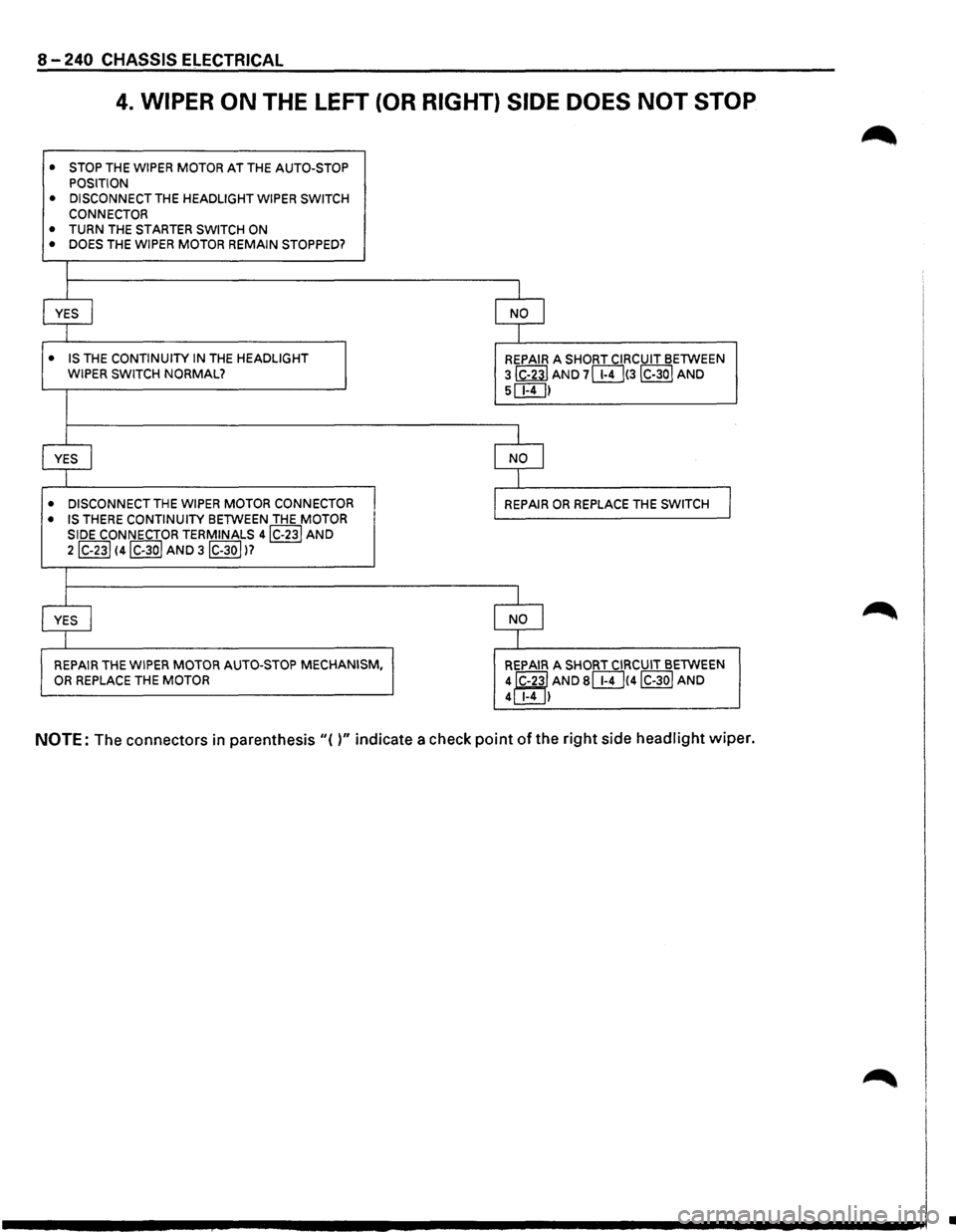
8-240 CHASSIS ELECTRICAL
4. WIPER ON THE LEFT (OR RIGHT) SIDE DOES NOT STOP
•
STOP THE WIPER MOTOR AT THE AUTO-STOP
POSITION
• DISCONNECT THE HEADLIGHT WIPER SWITCH
CONNECTOR
• TURN THE STARTER SWITCH ON
• DOES THE WIPER MOTOR REMAIN STOPPED?
I
YES
I NO I
I
• IS THE CONTINUITY IN THE HEADLIGHT
REPAIR A SHORT CIRCUIT BETWEEN WIPER SWITCH NORMAL? 3 ~AND 7lli]!3IC-30I AND
5c:E!]I
I
YES I NO I
I
• DISCONNECT THE WIPER MOTOR CONNECTOR
REPAIR OR REPLACE THE SWITCH I • IS THERE CONTINUITY BETWEEN THE MOTOR
SIDE CONNECTOR TERMINALS 4IC-23J AND
2lc-23l 14IC-3ol AND 3IC-30JI?
I
YES I NO I
I
REPAIR
THE WIPER MOTOR AUTO-STOP MECHANISM,
REPAIR A SHORT CIRCUIT BETWEEN OR REPLACE THE MOTOR
4J'C-23l AND slli]!4JC-30J AND 4 1-4 I
NOTE: The connectors in parenthesis "( )" indicate a check point of the right side headlight wiper.
•