air bleeding ISUZU TROOPER 1995 Workshop Manual
[x] Cancel search | Manufacturer: ISUZU, Model Year: 1995, Model line: TROOPER, Model: ISUZU TROOPER 1995Pages: 1928
Page 139 of 1928
POWER STEERING GEAR AND PUMP 381 -1
SECTION 381
POWER STEERING GEAR AND PUMP
w CAUTION:
When fasteners are removed, always reinstall them at the same location from which they were removed.
If a fastener needs to be replaced, use the correct part number fastener for that application. If the correct
part
number fastener is not available, a fastener of equal size and strength (or stronger) may be used.
Fasteners
that are not reused, and those requiring thread locking compound, will be called out. The correct
torque value must be used when installing fasteners that require it. If the above conditions are not
followed, parts or system damage could result.
CONTENTS
General Description ............................ 3B1- 1
Steering Wheel Free Play Adjustment .... 3B1-5
Power Steering
Gear........................ 3B1-1
Steering Gear ................................ 3B1-6
Hydraulic Pump .............................. 3B1- 1
Power Steering Pump ...................... 3B1-8
Pressure Switch
............................. 3B1-1
Unit Repair ...................................... 3B1- 9
Power Steering System Test
................. 3B1-3
Steering Gear ................................ 3B1-9
On-Vehicle Service ............................. 3B1- 4
Power Steering Pump ...................... 3B1-14
Maintenance
................................. 3B1- 4
Main Data and Specifications ................ 3B1-17
Fluid Level .................................... 3B1- 4 General Specifications ...................... 3B1-17
Bleeding The Power Steering System .... 3B1-4
Torque Specifications ....................... 3B1-17
Bleeding Procedure ......................... 3B1-4 Special Tools.................................... 3B1-18
Flushing The Power Steering System .... 3B1-4
GENERAL DESCRIPTION
The hydraulic power steering system consists of a
pump, an oil reservoir, a steering gear, a pressure
hose and a return hose.
POWER STEERING GEAR
The power steering gear has a recirculating ball
system which acts as a rolling thread between the
worm shaft and the rack piston. When the worm shaft
is
turned right, the rack piston moves up in gear.
Turning the worm shaft left moves the rack piston
down in gear. The rack piston teeth mesh with the
sector, which is part ofthe sector shaft.
Turning the worm shaft turns the sector shaft, which
turns the wheels through the steering linkage.
The control valve in the steering gear directs the
power steering fluid to either side of the rack piston.
The rack
piston converts the hydraulic pressure into
a mechanical force. If the steering system becomes
damaged and loses hydraulic pressure, the vehicle
can be controlled manually (Fig. 381-1).
HYDRAULIC PUMP
The hydraulic pump is vane-type design. The
submerged pump has housing and internal parts that
are inside the reservoir and operate submerged in oil.
There are two bore openings at the rear of the pump
housing. The larger opening contains the cam ring,
pressure
plate, thrust plate, rotor and vane assembly,
and end plate. The smaller opening contains the
pressure
line union, flow control valve and spring
(Fig. 381-2).
PRESSURE SWITCH
When hydraulic pressure reaches 3920 ± 690 kPa
(570 ± 100 psi), the pressure switch closes causing
Engine
Control Module (ECM) to actuate the idle air
control valve to prevent the overload-induced engine
speed down. The switch opens
when hydraulic
pressure drops to 2970 ± 560 kPa (430 ± 80 psi).
Page 141 of 1928
POWER STEERING SYSTEM TEST
TEST PROCEDURE
Test of fluid pressure in the power steering system is
performed to determine whether
or not the oil pump
and
power steering unit are functioning normally.
The power steering system test is method used to
identify and
isolate hydraulic circuit difficulties. Prior
to performing this test, the following inspections and
corrections,
if necessary, must be made.
[!) INSPECT
• Pump reservoir for proper fluid level.
•
Pump belt for proper tension.
• Pump driver pulley condition.
1. Place a container under the pump to catch the
fluid when disconnecting or connecting the
hoses.
2. With the engine NOT running, disconnect the
pressure hose
at the power steering pump and
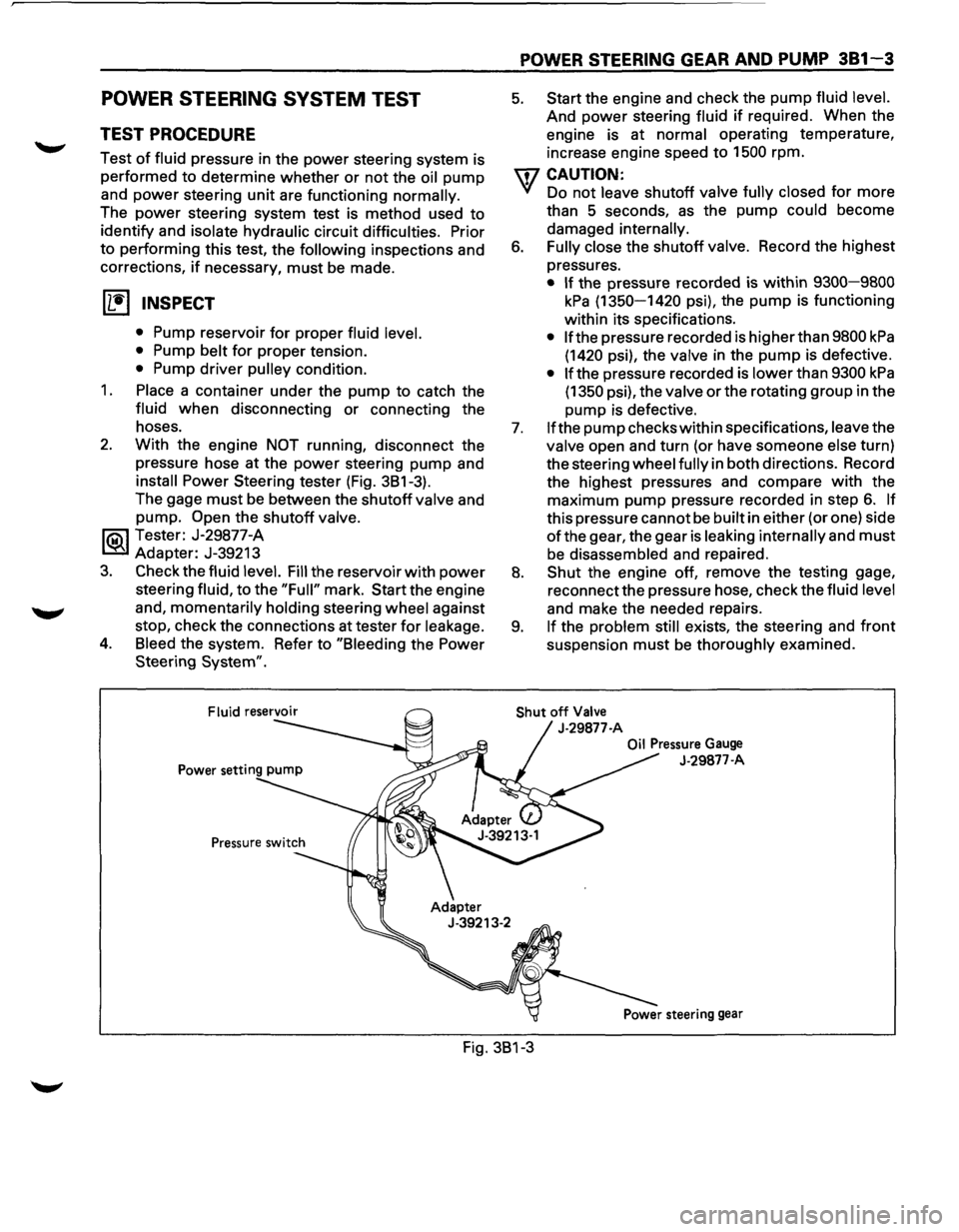
install Power Steering tester (Fig. 3B1-3).
The gage
must be between the shutoff valve and
pump.
Open the shutoff valve.
li5\l Tester: J-29877-A
~ Adapter: J-39213
3. Check the fluid level. Fill the reservoir with power
steering fluid, to the "Full" mark. Start the engine
and,
momentarily holding steering wheel against
stop, check the connections at tester
for leakage.
4. Bleed the system. Refer to "Bleeding the Power
Steering
System".
POWER STEERING GEAR AND PUMP 381-3
5. Start the engine and check the pump fluid level.
And power steering fluid if required. When the
engine is at
normal operating temperature,
increase engine speed to 1500 rpm.
U7 CAUTION:
VI Do not leave shutoff valve fully closed for more
than 5 seconds,
as the pump could become
damaged
internally.
6. Fully close the shutoff valve. Record the highest
pressures.
• If the pressure recorded is within 9300-9800
kPa (1350-1420 psi), the pump is functioning
within its specifications.
• If the pressure recorded is higher than 9800 kPa
(1420 psi), the valve in the pump is defective.
• If the pressure recorded is lower than 9300 kPa
(1350 psi), the valve or the rotating group in the
pump is defective.
7. If the pump checks within specifications, leave the
valve open and turn (or have someone else turn)
the steering
wheel fully in both directions. Record
the highest pressures and compare
with the
maximum pump pressure recorded in step
6. If
this pressure cannot be built in either (or one) side
ofthe gear, the gear is leaking internally and must
be disassembled and repaired.
8. Shut the engine off, remove the testing gage,
reconnect the pressure hose, check the
fluid level
and make the needed repairs.
9. If the problem still exists, the steering and front
suspension must be thoroughly examined.
Shut off Valve
J-29877-A
Oil Pressure Gauge
J-29877-A
Fig. 3B1-3
Page 142 of 1928
381 - 4 POWER STEERING GEAR AND PUMP
ON-VEHICLE SERVICE
MAINTENANCE
The hydraulic system should be kept clean and fluid
level in the reservoir should be checked at regular
intervals
and fluid added when required. Refer to
"MAINTENANCE AND LUBRICATION" in section OB
ofthe manual for type offluid to be used and intervals
for filling.
If the system contains some dirt, flush it as detailed
later
in this section. If it is exceptionally dirty, both the
pump and the gear must be completely disassembled
before further usage.
All tubes, hoses, and fittings should be inspected for
leakage at regular intervals. Fittings must be tight.
Make sure the clips, clamps and supporting tubes and
hoses are in
place and properly secured.
Power steering hoses and lines must not be twisted,
kinked or tightly bent. Air in the system will cause
spongy action and noisy operation. When a hose is
disconnected
or when fluid is lost, for any reason, the
system must be bled after refilling. Refer to "Bleeding
the Power Steering System" in this section.
FLUID LEVEL
1. Run the engine until the power steering fluid
reaches normal operating temperature, about
55°C (130°F), then shut the engine off.
2. Check the level of fluid in the reservoir.
3. If the fluid level is low, add power steering fluid
as specified in "MAINTENANCE AND LUBRI
CATION" in Section OB to the proper level and
install the receiver cap.
4. When checking the fluid level after the steering
system has been serviced,
air must be bled from
the system. Refer to "Bleeding the Power
Steering
System" in this section.
BLEEDING THE POWER STEERING
SYSTEM
When a power steering pump or gear has been
installed, or an oil line has been disconnected, the air
that has entered the system must be bled out before
the vehicle is operated. If air is allowed to remain in
the power steering fluid system, noisy and
unsatisfactory operation of the system may result.
BLEEDING PROCEDURE
When bleeding the system, and any time fluid is
added
to the power steering system, be sure to use
only power steering fluid as specified in
"MAINTENANCE AND LUBRICATION" in section OB.
1. Fill the pump fluid reservoir to the proper level
and let the fluid settle for at least two minutes.
2. Start the engine and let it run for a few seconds.
Do
not turn the steering wheel. Then turn the
engine off.
3. Add fluid if necessary.
4. Repeat the above procedure until the fluid level
remains constant after running the engine.
5. Raise the front end of the vehicle so that the
wheels are off the ground.
6. Start the engine. Slowly turn the steering wheel
right and left, lightly contacting the wheel stops.
7. Add power steering fluid if necessary.
8. Lower the vehicle and turn the steering wheel
slowly from lock to lock.
9. Stop the engine. Check the fluid level and refill
as required.
10.
If the fluid is extremely foamy, allow the vehicle
to stand a few minutes and repeat the above
procedure.
~ INSPECT
• Belt for tightness.
• Pulley for looseness or damage. The pulley
should not wobble with the engine running.
• Hoses so they are not touching any other parts
of the vehicle.
• Fluid level
and fill to the proper level.
FLUSHING THE POWER STEERING
SYSTEM
1. Raise the front end of the vehicle off the ground
until the wheels are free to turn.
2. Remove the fluid return line at the pump inlet
connector and plug the connector port on the
pump.
Position the line toward a large container to
catch the draining fluid.
3. While running the engine at idle, fill the reservoir
with new power steering fluid. Turn the steering
wheel in both directions. DO NOT contact wheel
stops or hold the wheel in a corner, or fluid will
stop and the pump will be in pressure relief mode.
A sudden
overflow from the reservoir may
develop if the wheel is held at a stop.
4. Install all the lines and hoses. Fill the system with
new power steering fluid and bleed the system
as described in "Bleeding The Power Steering
System". Operate the engine for about 15
minutes.
Remove the
pump return line at the pump inlet
and plug the connection on the pump. While
refilling the reservoir, check the draining fluid for
contamination. If foreign material is still evident,
replace all lines, disassemble and clean or replace
the power steering system components. Do not
re-use any drained power steering fluid.
~
~
Page 321 of 1928
HYDRAULIC BRAKES SA-1
BRAKES
w CAUTION:
• All
brake attaching fasteners are an important attaching part in that they could affect performance of vital
parts and systems, and/or could result in major repair expense. They must be replaced with one of the same
part
number or with an equivalent part if replacement becomes necessary. Do not use replacement parts of
lesser quality or substitute design. Torque values must be used as specified during reassembly to assure
proper retention
of these parts.
CONTENTS
Hydraulic Brakes . . . . . . . . . . . . . . . . . . . . . . . . . . . . . . . . . . . . . . . . . . . . . . . . . . . . . . . . . . . . . . Section SA
Brake Booster System ........................................................ Section 5A1
Disc Brakes . . . . . . . . . . . . . . . . . . . . . . . . . . . . . . . . . . . . . . . . . . . . . . . . . . . . . . . . . . . . . . . . . . Section 5A2
Rear
Wheel Antilock Brake System (RWAL) .................................... Section 5A3
4-Wheel Antilock Brake System (ABS) ......................................... Section 5A4
Parking Brakes . . . . . . . . . . . . . . . . . . . . . . . . . . . . . . . . . . . . . . . . . . . . . . . . . . . . . . . . . . . . . . . .
Section 5C
SECTION 5A
HYDRAULIC BRAKES
CONTENTS
Brake System Diagnosis ................ SA-2
Road
Testing the Brakes . . . . . . . . . . . . . . SA-2
Brake
Fluid Leaks . . . . . . . . . . . . . . . . . . . . SA-2
Warning Light Operation . . . . . . . . . . . . . SA-2
Antilock Brake System (RWAL or ABS) . SA- 2
Diagnosis of Brake System . . . . . . . . . . . . . . SA-3
On-Vehicle Service .................... SA- S
Filling Master Cylinder Reservoir . . . . . . . SA-S
Deterioration of Brake Fluid . . . . . . . . . . . SA-S
Leakage
of Brake Fluid . . . . . . . . . . . . . . . SA-S
Bleeding Brake Hydraulic System . . . . . . SA-S
Flushing Brake Hydraulic System . . . . . . SA-6
Brake Pipes
and Hoses . . . . . . . . . . . . . . . SA-6
Brake Hose
Inspection . . . . . . . . . . . . . . . SA-6
Brake Hose
Replacement . . . . . . . . . . . . . SA-7
Brake Pipe
Replacement . . . . . . . . . . . . . . SA-8
Combination Valve/P & B Valve . . . . . . . SA-9
Valve Replacement . . . . . . . . . . . . . . . . . . SA-1 0
Inspection of Brake Pad Lining . . . . . . . . SA-11
Inspection of Brake Rotors . . . . . . . . . . . . SA-11
Brake Pedal Assembly .................. SA-13 •
Checking Pedal Height ................ SA-13
Checking Pedal Travel ................ SA-13
Brake
Pedal Replacement ............. SA-14
Stoplight Switch Replacement ......... SA-1S
Master Cylinder Assembly ............... SA-16
General Description .................. SA-16
On-Vehicle Service ................... SA-17
Unit Repair .......................... SA-19
Main Data and Specifications ............ SA-21
General Specifications ................ SA-21
Torque Specifications ................ SA-21
Special Tools .......................... SA-22
Page 325 of 1928
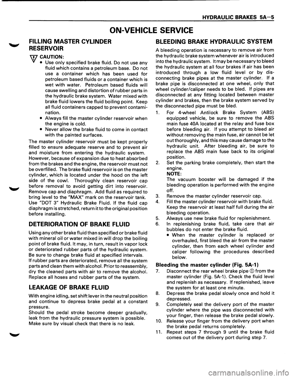
HYDRAULIC BRAKES 5A-5
ON-VEHICLE SERVICE
FILLING MASTER CYLINDER
RESERVOIR
'\fl CAUTION:
'VI • Use only specified brake fluid. Do not use any
fluid which contains a petroleum base. Do not
use a container which has been used for
petroleum based fluids or a container which is
wet with water. Petroleum based fluids will
cause swelling and distortion of rubber parts in
the
hydraulic brake system. Water mixed with
brake fluid lowers the fluid boiling point. Keep
all fluid containers capped to prevent contami
nation.
• Always fill the master cylinder reservoir when
the engine is
cold.
•
Never allow the brake fluid to come in contact
with the painted surfaces.
The master
cylinder reservoir must be kept properly
filled
to ensure adequate reserve and to prevent air
and moisture
from entering the hydraulic system.
However, because
of expansion due to heat absorbed
from the brakes and the engine, the reservoir must not
be overfilled. The brake fluid reservoir is on the master
cylinder, which is located under the hood on the
left
side of the cowl. Thoroughly clean reservoir cap
before
removal to avoid getting dirt into reservoir.
Remove cap and diaphragm.
Add fluid as required to
bring level to the "MAX" mark on the reservoir tank.
Use
"DOT 3" Hydraulic Brake Fluid. If the fluid cap
diaphragm is stretched, return
it to the original position
before
installing.
DETERIORATION OF BRAKE FLUID
Using any other brake fluid than specified or brake fluid
with mineral oil or water mixed in will drop the boiling
point of brake fluid. It may, in turn, result in vapor lock
or deteriorated rubber parts of the hydraulic system.
Be sure to change brake fluid at specified intervals.
If rubber parts are deteriorated, remove all the system
parts and
clean them with alcohol. Prior to reassembly,
dry the cleaned parts with air to remove the alcohol.
Replace all
hoses and rubber parts of the system.
LEAKAGE OF BRAKE FLUID
With engine idling, set shift lever in the neutral position
and continue to depress brake
pedal at a constant
pressure.
Should the pedal stroke become deeper gradually,
leak from the hydraulic pressure system is possible.
Make sure
by visual check that there is no leak.
BLEEDING BRAKE HYDRAULIC SYSTEM
A bleeding operation is necessary to remove air from
the hydraulic brake system whenever air is introduced
into the hydraulic system.
It may be necessary to bleed
the hydraulic system at all four brakes if air has been
introduced through a
low fluid level or by dis
connecting brake pipes at the master cylinder. If a
brake pipe is disconnected at one
wheel, only that
wheel cylinder/caliper needs to be bled. If pipes are
disconnected at any fitting
located between master
cylinder and brakes, then the brake system served by
the disconnected pipe must
be bled.
1. For 4-wheel Antilock Brake System (ABS)
equipped
vehicle, be sure to remove the ABS
main fuse
40A located at the relay and fuse box
before
bleeding air. If you attempt to bleed air
without removing the main fuse, air cannot be let
out thoroughly, and this may cause damage to the
hydraulic unit.
After bleeding air, be sure to
replace the ABS main fuse back to its original
position.
2. Set the parking brake completely, then start the
engine.
NOTE:
The vacuum booster will be damaged if the
bleeding operation is performed with the engine
off.
3. Remove the master cylinder reservoir cap.
4. Fill the master cylinder reservoir with brake fluid.
Keep the reservoir at least half full during the air
bleeding operation.
5. Always use new brake fluid for replenishment.
6. In replenishing brake fluid, take care that air
bubbles do not enter the brake fluid.
•
When the master cylinder is replaced or
overhauled, first bleed the air from the master
cylinder, then from each
wheel cylinder and
caliper following the procedures described
below.
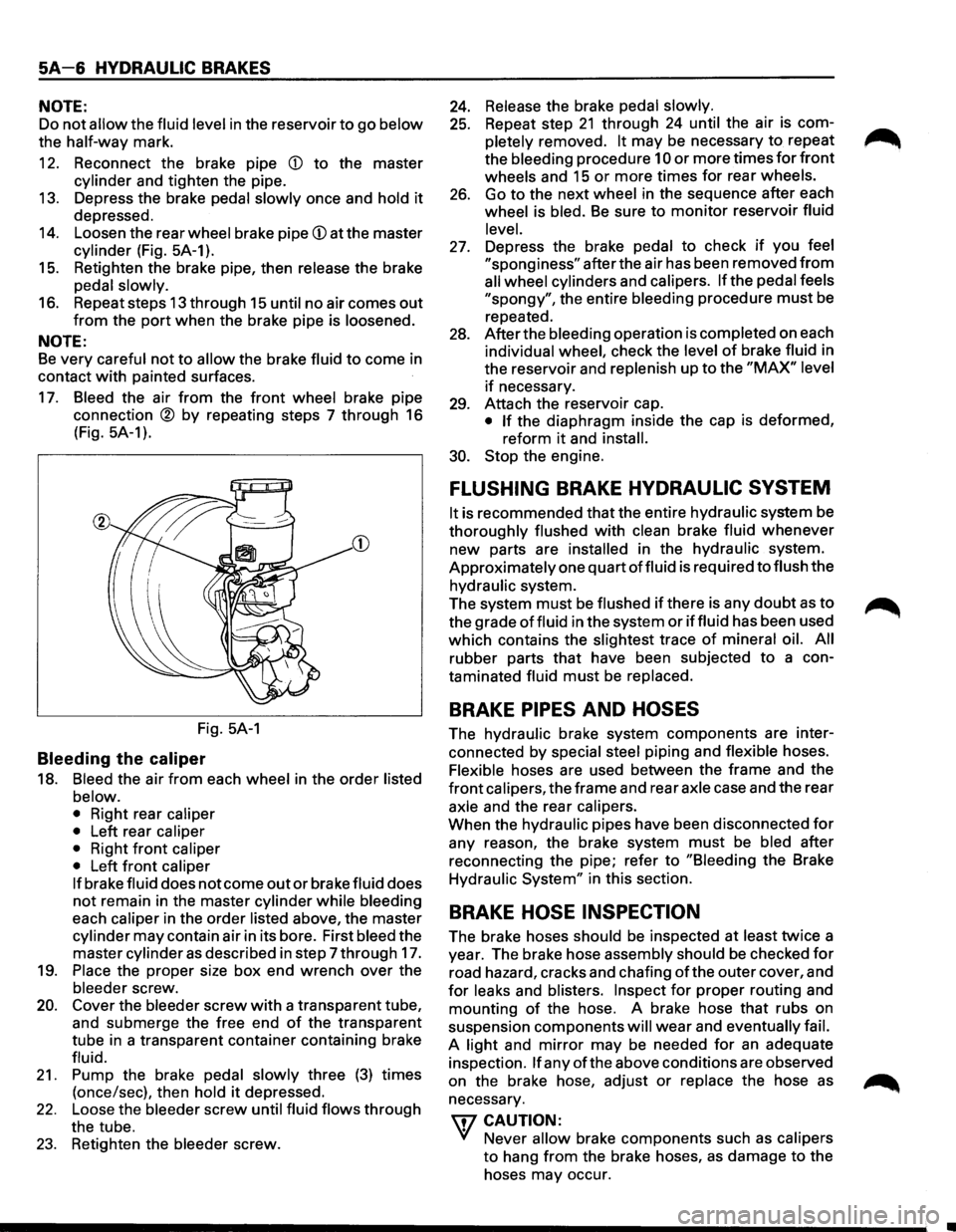
Bleeding the master cylinder (Fig. 5A-1}
7. Disconnect the rear wheel brake pipe
cylinder (Fig. 5A-1 ). Check the fluid level
and replenish as necessary. If replenished, leave
the system for at least one minute.
8. Depress the brake pedal slowly once and hold it
depressed.
9. Completely seal the delivery port of the master
cylinder where the pipe was disconnected with
your finger, then release the brake pedal slowly.
10. Release your finger from the delivery port when
the brake
pedal returns completely.
11. Repeat steps 7 through 9 until the brake fluid
comes out of the delivery port during step 7.
Page 326 of 1928
5A-6 HYDRAULIC BRAKES
NOTE:
Do not allow the fluid level in the reservoir to go below
the half-way mark.
12. Reconnect the brake pipe
(j) to the master
cylinder and tighten the pipe.
13. Depress the brake pedal
slowly once and hold it
depressed.
14. Loosen the rear wheel brake pipe (j) at the master
cylinder (Fig. 5A-1).
15. Retighten the brake pipe, then release the brake
pedal
slowly.
16. Repeat steps 13 through 15 until no air comes out
from the port when the brake pipe is loosened.
NOTE:
Be very careful not to allow the brake fluid to come in
contact
with painted surfaces.
17. Bleed the air from the front wheel brake pipe
connection
® by repeating steps 7 through 16
(Fig.
5A-1 ).
Fig. 5A-1
Bleeding the caliper
18. Bleed the air from each wheel in the order listed
below.
• Right rear caliper
• Left rear caliper
• Right front caliper
• Left front caliper
If brake fluid does not come out or brake fluid does
not remain in the master cylinder while bleeding
each
caliper in the order listed above, the master
cylinder may contain air in its bore. First bleed the
master cylinder
as described in step 7 through 17.
19.
Place the proper size box end wrench over the
bleeder screw.
20. Cover the bleeder screw with a transparent tube,
and submerge the free end
of the transparent
tube in a transparent container containing brake
fluid.
21. Pump the brake pedal slowly three (3) times
(once/sec), then
hold it depressed.
22. Loose the bleeder screw until fluid flows through
the tube.
23. Retighten the bleeder screw.
24. Release the brake pedal slowly.
25. Repeat step 21 through 24 until the air is com
pletely removed.
It may be necessary to repeat
the bleeding procedure
10 or more times for front
wheels and 15 or more times for rear wheels.
26. Go to the next wheel in the sequence after each
wheel is bled.
Be sure to monitor reservoir fluid
level.
27. Depress the brake pedal to check if you feel
"sponginess" after the air has been removed from
all wheel cylinders and calipers. If the pedal feels
"spongy", the entire bleeding procedure must be
repeated.
28. After the bleeding operation is completed on each
individual wheel, check the level
of brake fluid in
the reservoir and replenish up to the
"MAX" level
if necessary.
29. Attach the reservoir cap.
• If the diaphragm inside the cap is deformed,
reform
it and install.
30. Stop the engine.
FLUSHING BRAKE HYDRAULIC SYSTEM
It is recommended that the entire hydraulic system be
thoroughly flushed with clean brake fluid whenever
new parts are
installed in the hydraulic system.
Approximately one quart
of fluid is required to flush the
hydraulic system.
The system
must be flushed if there is any doubt as to
the grade
of fluid in the system or iffluid has been used
which contains the
slightest trace of mineral oil. All
rubber parts that have been subjected to a con
taminated fluid
must be replaced.
BRAKE PIPES AND HOSES
The hydraulic brake system components are inter
connected
by special steel piping and flexible hoses.
Flexible hoses are used between the frame and the
front calipers, the frame and rear axle case and the rear
axle and the rear calipers.
When the hydraulic pipes have been disconnected
for
any reason, the brake system must be bled after
reconnecting the pipe; refer to
"Bleeding the Brake
Hydraulic
System" in this section.
BRAKE HOSE INSPECTION
The brake hoses should be inspected at least twice a
year. The brake hose assembly should
be checked for
road hazard, cracks and chafing ofthe outer cover, and
for leaks and blisters. Inspect for proper routing and
mounting
of the hose. A brake hose that rubs on
suspension components
will wear and eventually fail.
A light and mirror may be needed for an adequate
inspection.
If any of the above conditions are observed
on the brake hose, adjust
or replace the hose as
necessary.
\fl CAUTION:
'V Never allow brake components such as calipers
to hang from the brake hoses, as damage to the
hoses may occur.
Page 333 of 1928
HYDRAULIC BRAKES SA-13
BRAKE PEDAL ASSEMBL V
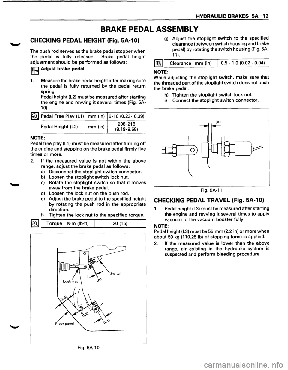
CHECKING PEDAL HEIGHT (Fig. SA-1 0)
The push rod serves as the brake pedal stopper when
the pedal is fully released. Brake pedal height
adjustment
should be performed as follows:
I~FI Adjust brake pedal
1. Measure the brake pedal height after making sure
the pedal is
fully returned by the pedal return
spring. Pedal height
(L2) must be measured after starting
the engine and revving
it several times (Fig. 5A-
10).
1~1 Pedal Free Play (L 1) mm (in) 6-10 (0.23- 0.39)
Pedal Height (L2)
NOTE:
mm (in) 208-218
(8.19-8.58)
Pedal free play (L 1) must be measured after turning off
the engine and stepping on the brake pedal firmly five
times
or more.
2. If the measured value is not within the above
range, adjust the brake
pedal as follows:
a) Disconnect the stoplight switch connector.
b) Loosen the stoplight switch lock nut.
c) Rotate the stoplight switch so that it moves
away
from the brake pedal.
d) Loosen the lock nut on the push rod.
e) Adjust the brake pedal to the specified height
by rotating the push rod in the appropriate
direction.
f) Tighten the lock nut to the specified torque.
~~~ Torque N·m (lb·ft) 20 (15) --------~----~---
Fig. 5A-10
g) Adjust the stoplight switch to the specified
clearance (between switch housing and brake
pedal)
by rotating the switch housing (Fig. 5A-
11 ).
1@1 Clearance mm (in) I 0.5-1.0 (0.02-0.04)
NOTE:
While adjusting the stoplight switch, make sure that
the threaded part of the stoplight switch does not push
the brake
pedal.
h) Tighten the stoplight switch lock nut.
i) Connect the stoplight switch connector.
Fig.
5A-11
CHECKING PEDAL TRAVEL (Fig. SA-1 0)
1. Pedal height (L3) must be measured after starting
the engine and revving
it several times to apply
vacuum
to the vacuum booster fully.
NOTE:
Pedal height (L3) must be 55 mm (2.2 in) or more when
about 50 kg (11 0.25 I b) of stepping force is applied.
2. If the measured value is lower than the above
range, air existing in the hydraulic system is
suspected and perform bleeding procedure.
Page 515 of 1928
ENGINE DIAGNOSIS 6-17
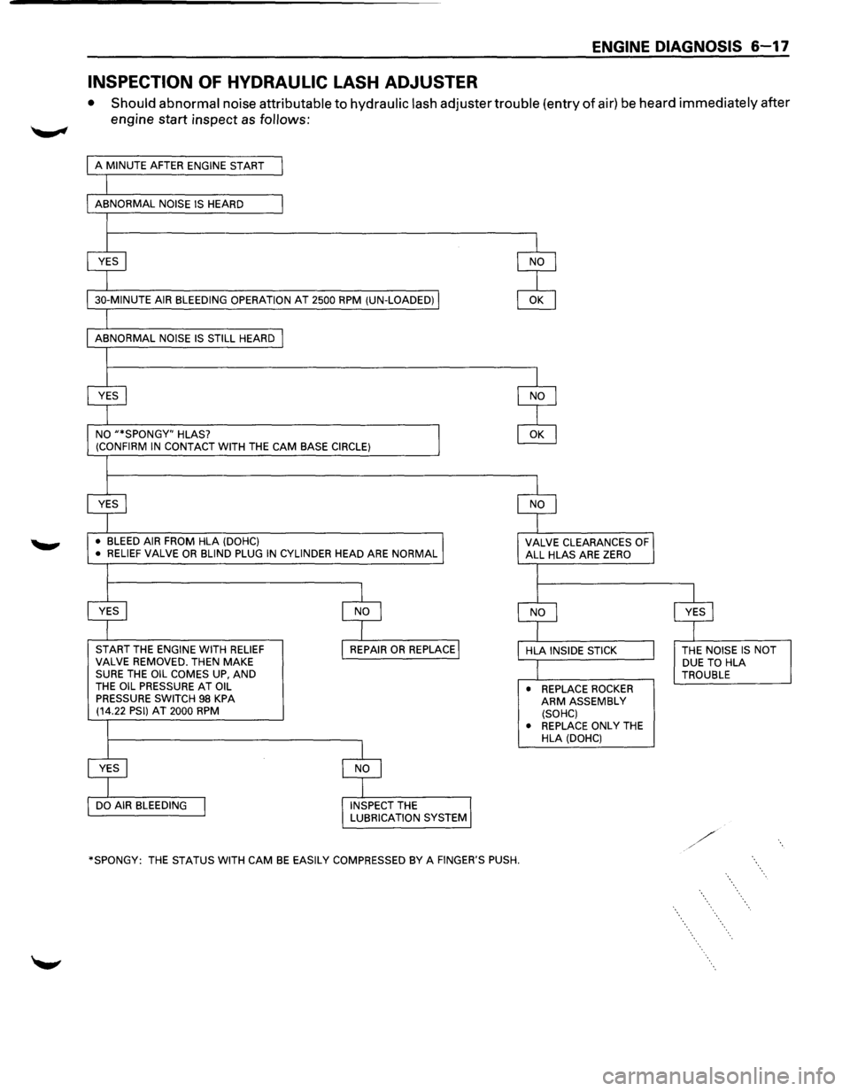
INSPECTION OF HYDRAULIC LASH ADJUSTER
• Should abnormal noise attributable to hydraulic lash adjuster trouble (entry of air) be heard immediately after
engine start inspect
as follows:
30-MINUTE AIR BLEEDING OPERATION AT 2500 RPM (UN-LOADED)
NO
"*SPONGY" HLAS?
(CONFIRM IN CONTACT WITH THE CAM BASE CIRCLE)
•
BLEED AIR FROM HLA (DOHC)
• RELIEF VALVE OR BLIND PLUG IN CYLINDER HEAD ARE NORMAL
START THE ENGINE WITH RELIEF VALVE REMOVED. THEN MAKE SURE THE OIL COMES UP, AND
THE OIL PRESSURE AT OIL
PRESSURE SWITCH 98 KPA (14.22 PSI) AT 2000 RPM
*SPONGY:
THE STATUS WITH CAM BE EASILY COMPRESSED BY A FINGER'S PUSH. •
REPLACE
ROCKER ARM ASSEMBLY
(SOHC)
• REPLACE
ONLY THE
HLA (DOHC) THE
NOISE IS NOT
DUE TO HLA
TROUBLE
Page 524 of 1928
&A-8 GENERAL ENGINE MECHANICAL
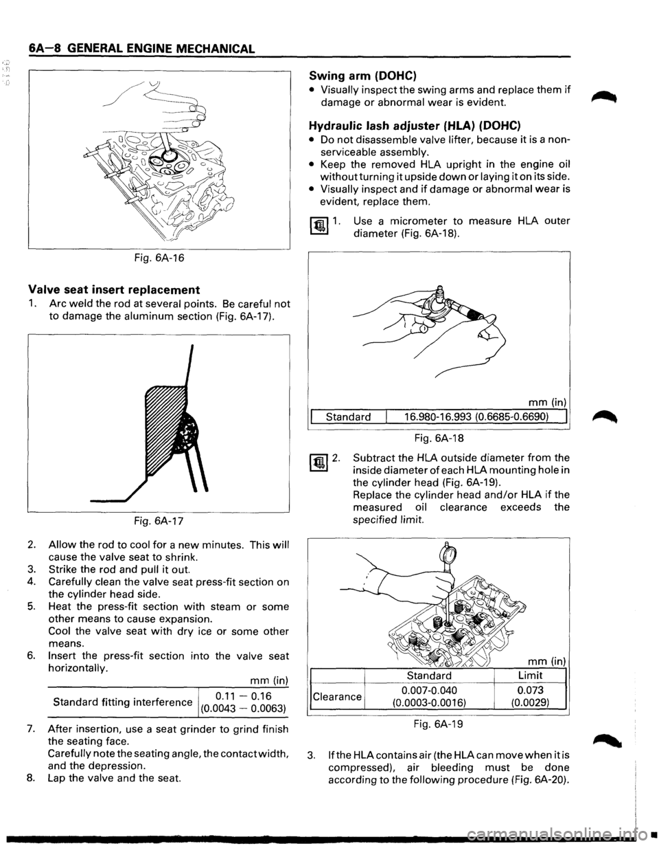
Fig. 6A-16
Valve seat insert replacement
1. Arc weld the rod at several points. Be careful not
to damage the aluminum section (Fig. 6A-17).
Fig. 6A-17
2. Allow the rod to cool for a new minutes. This will
cause the valve seat to shrink.
3. Strike the rod and pull it out.
4. Carefully clean the valve seat press-fit section on
the
cylinder head side.
5. Heat the press-fit section with steam or some
other means
to cause expansion.
Cool the valve seat with dry ice or some other
means.
6. Insert the press-fit section into the valve seat
horizontally.
mm (in)
S d df. 0 0 f 0.11-0.16 tan ar 1tt1ng 1nter erence (0.0043 _ 0_
0063 )
7. After insertion,
use a seat grinder to grind finish
the seating face.
Carefully note the seating angle, the contact width,
and the depression.
8. Lap the valve and the seat.
Swing arm (DOHC)
• Visually inspect the swing arms and replace them if
damage or abnormal wear is evident.
Hydraulic lash adjuster (HLA) (DOHC}
• Do not disassemble valve lifter, because it is a non
serviceable assembly.
•
Keep the removed HLA upright in the engine oil
withoutturning it upside down or laying it on its side.
• Visually inspect and if damage or abnormal wear is
evident,
replace them.
[§) 1. Use a micrometer to measure HLA outer
diameter (Fig. 6A-18).
mm (in)
Standard 16.980-16.993
(0.6685-0.6690) I
Fig.
6A-18
Subtract the HLA outside diameter
from the
inside diameter
of each HLA mounting hole in
the
cylinder head (Fig. 6A-19).
Replace the cylinder head and/or HLA if the
measured
oil clearance exceeds the
specified
limit.
Clearance 0.007-0.040
(0.0003-0.0016)
Fig. 6A-19
mm (in)
0.073
(0.0029)
3. lfthe HLA contains air (the HLA can move when it is
compressed). air
bleeding must be done
according
to the following procedure (Fig. 6A-20).
•
Page 1149 of 1928
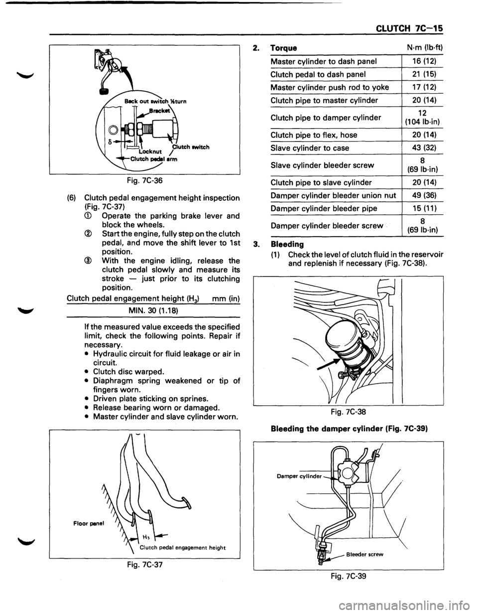
Fig. 7C-36
(6) Clutch pedal engagement height inspection
(Fig.
7C-37)
® Start the engine, fully step on the clutch
pedal,
and move the shift lever to 1st
position.
@ With the engine idling, release the
clutch pedal slowly and measure its
stroke -just prior
to its clutching
position.
Clutch pedal engagement height (H3) mm (in)
MIN. 30 (1.18)
If the
measured value exceeds the specified
limit, check the following points. Repair if
necessary.
• Hydraulic circuit for fluid leakage or air in
circuit.
• Clutch disc warped.
• Diaphragm spring weakened or tip of
fingers worn.
• Driven plate sticking on sprines.
• Release bearing worn or damaged.
• Master cylinder and slave cylinder worn.
Floor panel
Fig. 7C-37
CLUTCH 7C-15
2. Torque N·m (lb·ft)
Master cylinder to dash panel 16 (12)
Clutch pedal to dash panel 21 (15)
Master cylinder push rod to yoke 17 (12)
Clutch pipe to master cylinder 20 (14)
Clutch pipe
to damper cylinder 12
(104 lb·in)
Clutch
pipe to flex, hose 20 (14)
Slave cylinder to case 43 (32)
Slave
cylinder bleeder screw 8 (691b·in)
Clutch
pipe to slave cylinder 20 (14)
Damper cylinder bleeder union nut 49 (36)
Damper cylinder bleeder pipe 15 (11)
Damper cylinder
bleeder screw 8 (69 lb·in)
3. Bleeding
(1) Check
the level of clutch fluid in the reservoir
and
replenish if necessary (Fig. 7C-38).
Fig. 7C-38
Bleeding the damper cylinder (Fig. 7C-39)
Damper cylinder
Fig. 7C-39