display ISUZU TROOPER 1995 Service Manual
[x] Cancel search | Manufacturer: ISUZU, Model Year: 1995, Model line: TROOPER, Model: ISUZU TROOPER 1995Pages: 1928
Page 762 of 1928
6E2-66 DRIVEABILITV AND EMISSIONS
DIAGNOSTIC TROUBLE CODE (DTC) 21 8
THROTILE POSITION (TP) SENSOR CIRCUIT
(SIGNAL VOLTAGE LOW)
Circuit Description:
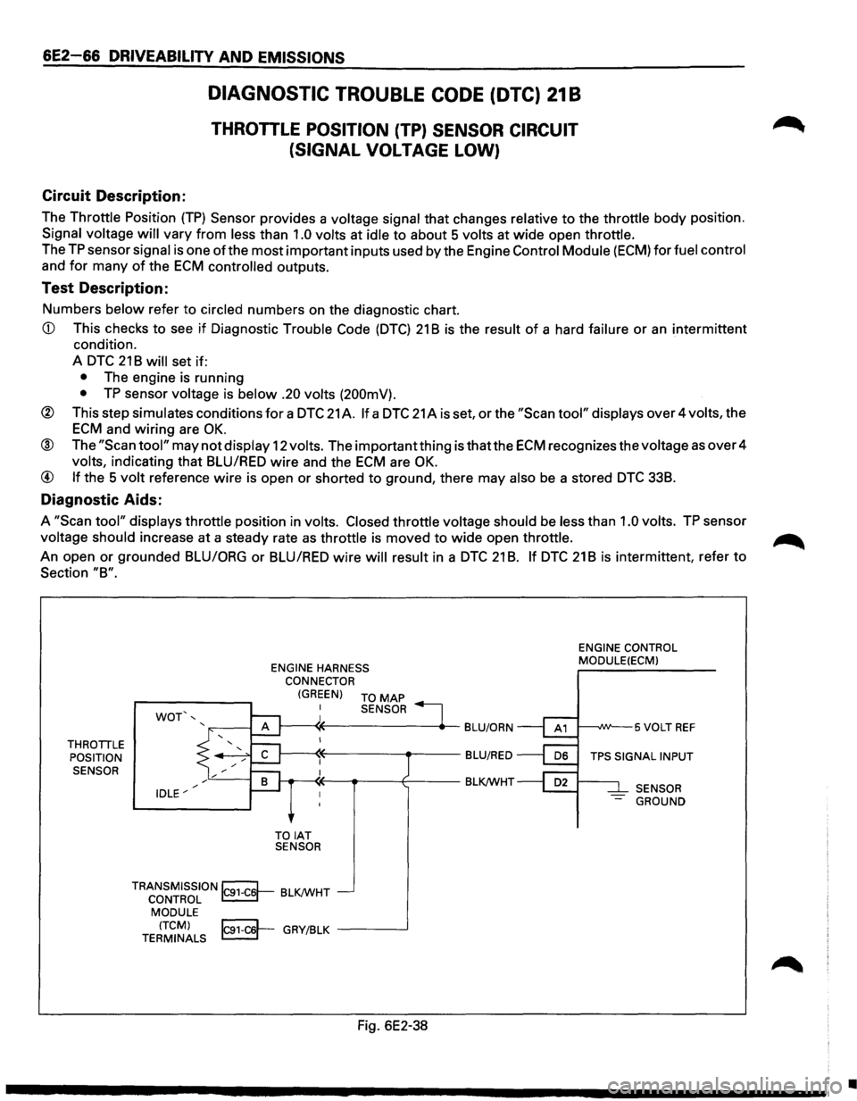
The Throttle Position (TP) Sensor provides a voltage signal that changes relative to the throttle body position.
Signal voltage will vary from less than 1.0 volts at idle to about 5 volts at wide open throttle.
The
TP sensor signal is one of the most important inputs used by the Engine Control Module (ECM) for fuel control
and
for many of the ECM controlled outputs.
Test Description:
Numbers below refer to circled numbers on the diagnostic chart.
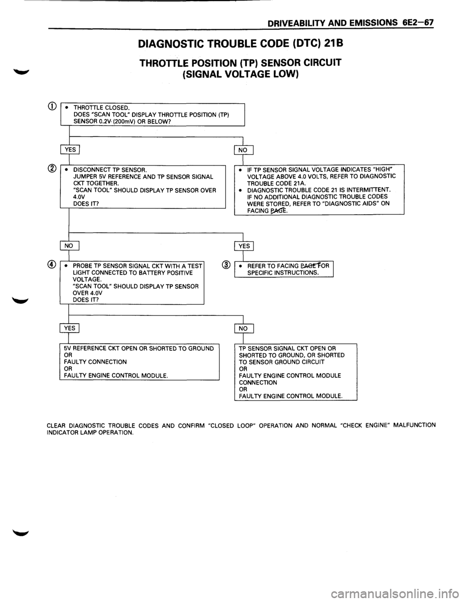
CD This checks to see if Diagnostic Trouble Code (DTC) 21 B is the result of a hard failure or an intermittent
condition.
A
DTC 21 B will set if:
• The engine is running
• TP sensor voltage is below .20 volts (200mV).
® This step simulates conditions for a DTC 21 A. If a DTC 21 A is set, or the "Scan tool" displays over 4 volts, the
ECM and wiring are OK.
® The "Scan tool" may not display 12 volts. The important thing is thatthe ECM recognizes the voltage as over 4
volts, indicating that BLU/RED wire and the ECM are OK.
@ If the 5 volt reference wire is open or shorted to ground, there may also be a stored DTC 338.
Diagnostic Aids:
A "Scan tool" displays throttle position in volts. Closed throttle voltage should be less than 1.0 volts. TP sensor
voltage should increase at
a steady rate as throttle is moved to wide open throttle. ~
An open or grounded BLU/ORG or BLUIRED wire will result in a DTC 21 B. If DTC 21 B is intermittent, refer to
Section "8".
THROTTLE POSITION
SENSOR ENGINE
HARNESS
CONNECTOR
WOT',
IDLE"'
(GREEN) TO MAP
TOIAT SENSOR SENSOR
TRANSMISSION~ BLK/WHT CONTROL ~ MODULE
(TCM) IC91-C6'-GRY/BLK -----..J TERMINALS ~ -
Fig. 6E2-38
ENGINE
CONTROL
MODULE(ECMl
1---..JW--5 VOLT REF
TPS SIGNAL INPUT
SENSOR
- GROUND
•
Page 763 of 1928
Q)
DRIVEABILITV AND EMISSIONS 6E2-67
DIAGNOSTIC TROUBLE CODE (DTC) 21 B
THROTTLE POSITION (TP) SENSOR CIRCUIT
(SIGNAL
VOLTAGE LOW)
• THROTTLE CLOSED.
DOES "SCAN TOOL" DISPLAY THROTTLE POSITION (TP) SENSOR 0.2V· (200mV) OR BELOW?
~ $
• DISCONNECT TP SENSOR. • IF TP SENSOR
SIGNAL VOLTAGE INDICATES "HIGH" JUMPER 5V REFERENCE AND TP SENSOR SIGNAL VOLTAGE
ABOVE 4.0 VOLTS, REFER TO DIAGNOSTIC CKT TOGETHER. TROUBLE CODE 21A. "SCAN TOOL" SHOULD DISPLAY TP SENSOR OVER • DIAGNOSTIC TROUBLE CODE 21 IS INTERMITTENT.
4.0V IF NO ADDITIONAL DIAGNOSTIC TROUBLE CODES
DOES IT? WERE STORED, REFER TO "DIAGNOSTIC AIDS" ON FACING~.
LfJ ~
• PROBE TP SENSOR SIGNAL CKT WITH A TEST @ • REFER To FACING EAe'E'1oR J LIGHT CONNECTED TO BATTERY POSITIVE SPECIFIC INSTRUCTIONS.
VOLTAGE.
"SCAN TOOL" SHOULD DISPLAY TP SENSOR
OVER 4.0V
DOES
IT?
~ $
5V REFERENCE CKT OPEN OR SHORTED TO GROUND TP SENSOR SIGNAL CKT OPEN OR
OR SHORTED TO GROUND, OR SHORTED FAULTY CONNECTION
TO SENSOR GROUND CIRCUIT OR
OR FAULTY ENGINE CONTROL MODULE. FAULTY ENGINE CONTROL MODULE CONNECTION OR FAULTY ENGINE CONTROL MODULE.
CLEAR
DIAGNOSTIC TROUBLE CODES AND CONFIRM "CLOSED LOOP" OPERATION AND NORMAL "CHECK ENGINE" MALFUNCTION
INDICATOR LAMP OPERATION.
Page 764 of 1928
6E2-68 DRIVEABILITV AND EMISSIONS
DIAGNOSTIC TROUBLEL CODE (DTC) 23A
INTAKE AIR TEMPERATURE {IAT) SENSOR CIRCUIT
(LOW TEMPERATURE INDICATED)
Circuit Description:
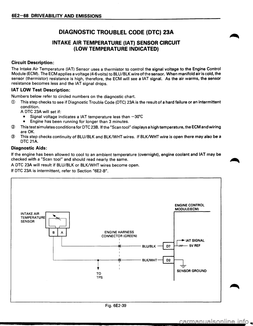
The Intake Air Temperature (IAT) Sensor uses a thermistor to control the signal voltage to the Engine Control
Module
(ECM). The ECM applies a voltage (4-6volts) to BLU/BLK wire of the sensor. When manifold air is cold, the
sensor (thermistor) resistance is high, therefore, the
ECM will see a IAT signal. As the air warms, the sensor
resistance becomes
less and the IAT signal drops.
IAT LOW Test Description:
Numbers below refer to circled numbers on the diagnostic chart.
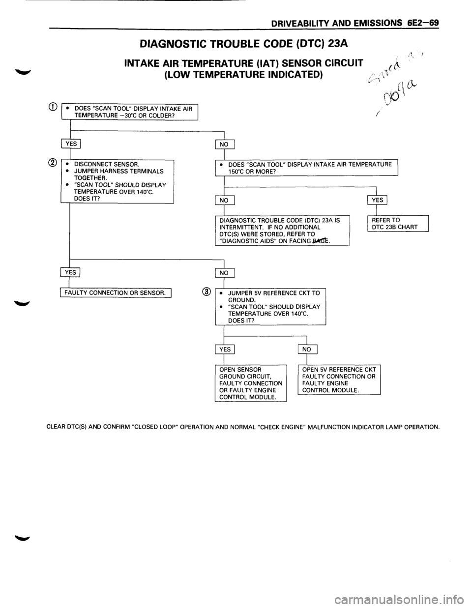
CD This step checks to see if Diagnostic Trouble Code (DTC) 23A is the result of a hard failure or an intermittent
condition.
A
DTC 23A will set if:
• Signal voltage indicates a IAT temperature less than -30"C
• Engine has been running for longer than 3 minutes.
® This test simulates conditions for DTC 238. If the "Scan tool" displays a high temperature, the ECM and wiring
are OK.
@ This step checks continuity of BLU/BLK and BLK/WHT wires. If BLK/WHT wire is open there may also be a
DTC 21A.
Diagnostic Aids:
If the engine has been allowed to cool to an ambient temperature (overnight), engine coolant and IAT may be
checked
with a "Scan tool" and should read nearly the same. ~
A DTC 23A will result if BLU/BLK or BLK/WHT wires become open.
If DTC 23A is intermittent, refer to Section "6E2-B".
INTAKE AIR TEMPERATURE SENSOR
ENGINE HARNESS
CONNECTOR
(GREEN) I
L-----------«----BLU/BLK
TO TPS
Fig. 6E2-39
ENGINE CONTROL
MODULE(ECM)
IATSIGNAL
1--'--IW'--5V REF
SENSOR GROUND
Page 765 of 1928
DRIVEABILITV AND EMISSIONS 6E2-69
DIAGNOSTIC TROUBLE CODE (DTC) 23A
INTAKE AIR TEMPERATURE (IAT) SENSOR CIRCUIT
(LOW
TEMPERATURE INDICATED)
DOES "SCAN TOOL" DISPLAY INTAKE AIR TEMPERATURE -30"C OR COLDER?
@ • DISCONNECT SENSOR.
• JUMPER HARNESS TERMINALS TOGETHER. • "SCAN TOOL" SHOULD DISPLAY TEMPERATURE OVER 140"C.
DOES IT?
FAULTY CONNECTION OR SENSOR.
I
• DOES "SCAN TOOL" DISPLAY INTAKE AIR TEMPERATURE 150"C OR MORE?
DIAGNOSTIC
TROUBLE CODE (DTC) 23A IS
INTERMITTENT. IF NO ADDITIONAL
DTC(S) WERE STORED, REFER TO
"DIAGNOSTIC AIDS" ON FACING~-
@ • JUMPER 5V REFERENCE CKT TO GROUND. • "SCAN TOOL" SHOULD DISPLAY TEMPERATURE OVER 140"C.
DOES IT?
OPEN SENSOR
GROUND CIRCUIT,
FAULTY CONNECTION OR FAULTY ENGINE
CONTROL MODULE.
OPEN 5V REFERENCE CKT FAULTY CONNECTION OR FAULTY ENGINE
CONTROL MODULE.
/~ i
CLEAR DTC(S) AND CONFIRM "CLOSED LOOP" OPERATION AND NORMAL "CHECK ENGINE" MALFUNCTION INDICATOR LAMP OPERATION.
Page 767 of 1928
DRIVEABILITV AND EMISSIONS 6E2-71
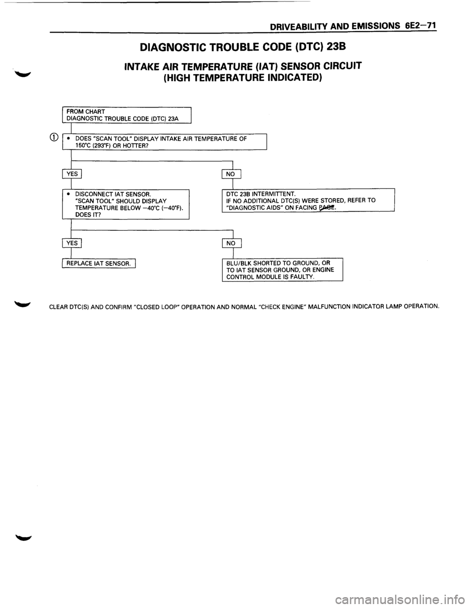
DIAGNOSTIC TROUBLE CODE (DTC) 238
INTAKE AIR TEMPERATURE (IAT) SENSOR CIRCUIT
(HIGH
TEMPERATURE INDICATED)
FROM CHART
DIAGNOSTIC TROUBLE CODE (DTC) 23A
G) • DOES "SCAN TOOL" DISPLAY INTAKE AIR TEMPERATURE OF 15o•c (293.F) OR HOTIER?
• DISCONNECT IAT SENSOR.
"SCAN TOOL" SHOULD DISPLAY
TEMPERATURE BELOW -4o·c (-40.F). DOES IT? DTC
23B INTERMITIENT. IF NO
ADDITIONAL DTC(S) WERE STORED, REFER TO
"DIAGNOSTIC AIDS" ON FACING ~-
BLU/BLK SHORTED TO GROUND, OR TO IAT SENSOR GROUND, OR ENGINE CONTROL MODULE IS FAULTY.
CLEAR DTC(S) AND CONFIRM "CLOSED LOOP" OPERATION AND NORMAL "CHECK ENGINE" MALFUNCTION INDICATOR LAMP OPERATION.
Page 769 of 1928
DRIVEABILITY AND EMISSIONS 6E2-73
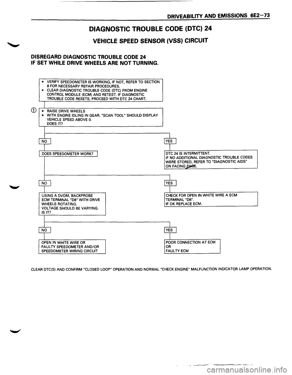
DIAGNOSTIC TROUBLE CODE (DTC) 24
VEHICLE SPEED SENSOR (VSS) CIRCUIT
DISREGARD DIAGNOSTIC TROUBLE CODE 24
IF SET WHILE DRIVE WHEELS ARE NOT TURNING.
• VERIFY SPEEDOMETER IS WORKING, IF NOT, REFER TO SECTION 8 FOR NECESSARY REPAIR PROCEDURES. • CLEAR DIAGNOSTIC TROUBLE CODE (DTC) FROM ENGINE CONTROL MODULE (ECM) AND RETEST. IF DIAGNOSTIC TROUBLE CODE RESETS, PROCEED WITH DTC 24 CHART.
CD • RAISE DRIVE WHEELS • WITH ENGINE IDLING IN GEAR, "SCAN TOOL" SHOULD DISPLAY VEHICLE SPEED ABOVE 0. DOES IT?
$ ~
DOES SPEEDOMETER WORK? I DTC 24 IS INTERMITIENT. IF NO ADDITIONAL DIAGNOSTIC TROUBLE CODES WERE STORED, REFER TO "DIAGNOSTIC AIDS" ON FACING~.
CfJ ~ USING A DVOM, BACKPROBE CHECK FOR OPEN IN WHITE WIRE A ECM
ECM TERMINAL "D8" WITH DRIVE TERMINAL "D8". WHEELS ROTATING. IF OK REPLACE ECM. VOLTAGE SHOULD BE VARYING. IS IT?
$ ~ OPEN IN WHITE WIRE OR POOR CONNECTION AT ECM FAULTY SPEEDOMETER AND/OR OR SPEEDOMETER WIRING CIRCUIT FAULTY ECM
CLEAR DTC(S) AND CONFIRM "CLOSED LOOP" OPERATION AND NORMAL "CHECK ENGINE" MALFUNCTION INDICATOR LAMP OPERATION.
-~---
Page 773 of 1928
CD
®
DRIVEABILITY AND EMISSIONS 6E2-77
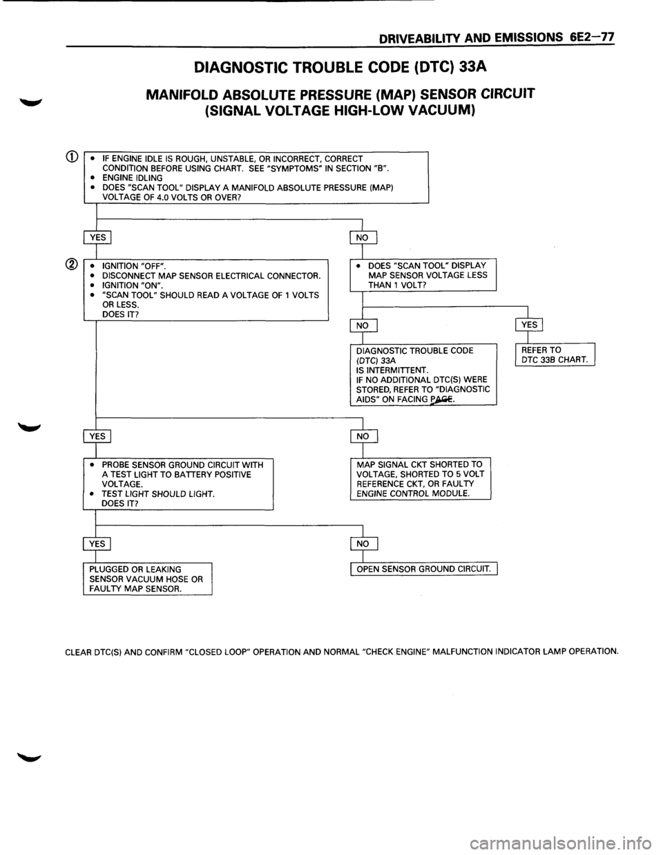
DIAGNOSTIC TROUBLE CODE (DTC) 33A
MANIFOLD ABSOLUTE PRESSURE (MAP) SENSOR CIRCUIT
(SIGNAL
VOLTAGE HIGH-LOW VACUUM)
• IF ENGINE IDLE IS ROUGH, UNSTABLE, OR INCORRECT, CORRECT CONDITION BEFORE USING CHART. SEE "SYMPTOMS" IN SECTION "B". • ENGINE IDLING
• DOES "SCAN TOOL" DISPLAY A MANIFOLD ABSOLUTE PRESSURE (MAP)
VOLTAGE OF 4.0 VOLTS OR OVER?
~ $
• IGNITION "OFF". •
DOES "SCAN TOOL" DISPLAY
• DISCONNECT MAP SENSOR ELECTRICAL CONNECTOR. MAP SENSOR VOLTAGE LESS
• IGNITION "ON". THAN 1 VOLT? • "SCAN TOOL" SHOULD READ A VOLTAGE OF 1 VOLTS I OR LESS.
DOES IT?
$ $
DIAGNOSTIC TROUBLE
CODE l REFER TO J (DTC) 33A DTC
33B CHART. IS INTERMITTENT. IF NO ADDITIONAL DTC(S) WERE STORED, REFER TO "DIAGNOSTIC AIDS" ON FACING ~-
~ $
• PROBE SENSOR GROUND CIRCUIT WITH MAP SIGNAL CKT SHORTED TO A TEST LIGHT TO BATTERY POSITIVE VOLTAGE,
SHORTED TO 5 VOLT
VOLTAGE. REFERENCE CKT, OR FAULTY • TEST LIGHT SHOULD LIGHT. ENGINE CONTROL MODULE.
DOES IT?
$ $
PLUGGED OR LEAKING OPEN SENSOR GROUND CIRCUIT.
SENSOR VACUUM HOSE OR FAULTY MAP SENSOR.
CLEAR DTC(S) AND CONFIRM "CLOSED LOOP" OPERATION AND NORMAL "CHECK ENGINE" MALFUNCTION INDICATOR LAMP OPERATION.
Page 774 of 1928
6E2-78 DRIVEABILITV AND EMISSIONS
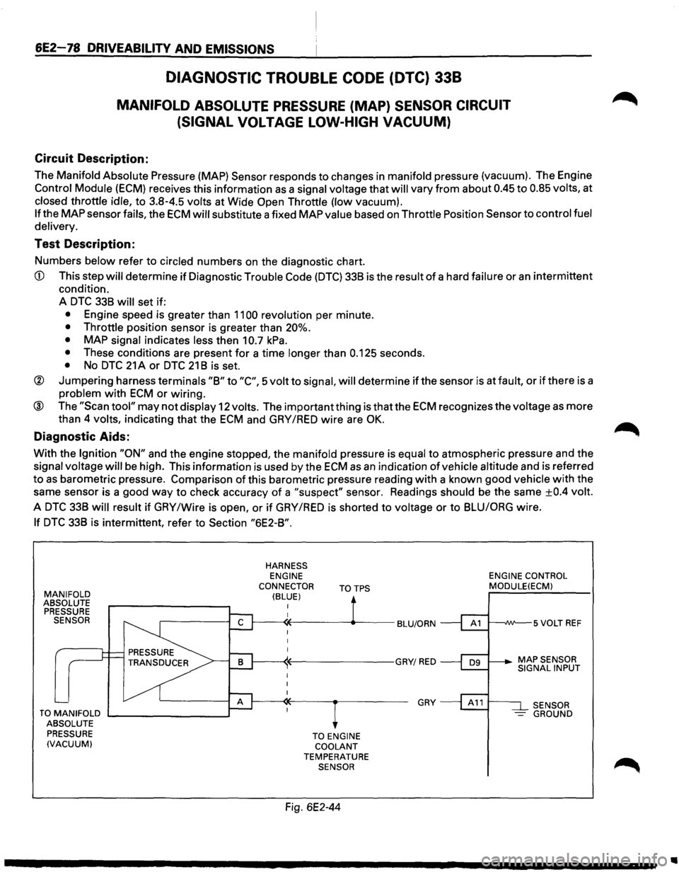
DIAGNOSTIC TROUBLE CODE (DTC) 338
MANIFOLD ABSOLUTE PRESSURE (MAP) SENSOR CIRCUIT
(SIGNAL
VOLTAGE LOW-HIGH VACUUM)
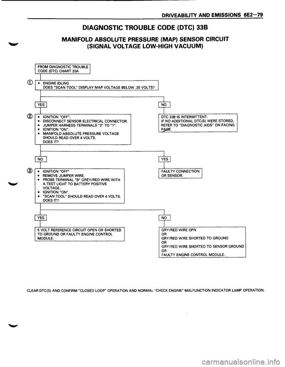
Circuit Description:
The Manifold Absolute Pressure (MAP) Sensor responds to changes in manifold pressure (vacuum). The Engine
Control Module (ECM) receives this information as a signal voltage that will vary from about 0.45 to 0.85 volts, at
closed throttle idle, to 3.8-4.5 volts at Wide Open Throttle (low vacuum).
If the MAP sensor fails, the ECM will substitute a fixed MAP value based on Throttle Position Sensor to control fuel
delivery.
Test Description:
Numbers below refer to circled numbers on the diagnostic chart.
CD This step will determine if Diagnostic Trouble Code (DTC) 338 is the result of a hard failure or an intermittent
condition.
A
DTC 338 will set if:
• Engine speed is greater than 1100 revolution per minute.
• Throttle position sensor is greater than 20%.
•
MAP signal indicates less then 10.7 kPa.
• These conditions are present for a time longer than 0.125 seconds.
• No DTC 21 A or DTC 21 8 is set.
® Jumpering harness terminals "8" to "C", 5 volt to signal, will determine if the sensor is at fault, or if there is a
problem with ECM or wiring.
® The "Scan tool" may not display 12 volts. The important thing is that the ECM recognizes the voltage as more
than 4
volts, indicating that the ECM and GAY /RED wire are OK.
Diagnostic Aids:
With the Ignition "ON" and the engine stopped, the manifold pressure is equal to atmospheric pressure and the
signal voltage will be high. This information is used by the ECM as an indication of vehicle altitude and is referred
to as barometric pressure. Comparison of this barometric pressure reading with a known good vehicle with the
same sensor is a good
way to check accuracy of a "suspect" sensor. Readings should be the same ±0.4 volt.
A DTC 338 will result if GAY /Wire is open, or if GAY /RED is shorted to voltage or to 8LUIORG wire.
If DTC 338 is intermittent, refer to Section "6E2-8".
MANIFOLD ABSOLUTE
PRESSURE SENSOR
TO MANIFOLD .._ _______ --.~
ABSOLUTE
PRESSURE
(VACUUM)
HARNESS ENGINE
CONNECTOR
(BLUE) TOTPS
TO ENGINE COOLANT TEMPERATURE SENSOR
Fig. 6E2-44
GRY
ENGINE CONTROL MODULE(ECM)
SENSOR -GROUND
..
Page 775 of 1928
DRIVEABILITY AND EMISSIONS 6E2-79
DIAGNOSTIC TROUBLE CODE (DTC) 338
MANIFOLD ABSOLUTE PRESSURE (MAP) SENSOR CIRCUIT
(SIGNAL VOLTAGE LOW-HIGH
VACUUM)
CD • ENGINE IDLING
DOES "SCAN TOOL" DISPLAY MAP VOLTAGE BELOW .25 VOLTS?
@ • IGNITION "OFF".
• DISCONNECT SENSOR ELECTRICAL CONNECTOR.
•
JUMPER HARNESS TERMINALS "2" TO "1". • IGNITION "ON". • MANIFOLD ABSOLUTE PRESSURE VOLTAGE SHOULD READ OVER 4 VOLTS.
DOES IT?
@ • IGNITION "OFF"
• REMOVE JUMPER WIRE.
• PROBE TERMINAL "B" GREY /RED WIRE WITH 'W' A TEST LIGHT TO BATTERY POSITIVE VOLTAGE. • IGNITION "ON". • "SCAN TOOL" SHOULD READ OVER 4 VOLTS.
DOES IT?
5 VOLT REFERENCE CIRCUIT OPEN OR SHORTED
TO GROUND OR FAUL TV ENGINE CONTROL MODULE.
DTC 33B IS INTERMITTENT. IF NO ADDITIONAL DTC{S) WERE STORED, REFER TO "DIAGNOSTIC AIDS" ON FACING p
GRY/RED WIRE OPN OR GRY/RED WIRE SHORTED TO GROUND OR GRY/RED WIRE SHORTED TO SENSOR GROUND OR FAUL TV ENGINE CONTROL MODULE.
CLEAR DTC{S) AND CONFIRM "CLOSED LOOP" OPERATION AND NORMAL "CHECK ENGINE" MALFUNCTION INDICATOR LAMP OPERATION.
Page 778 of 1928
6E2-82 DRIVEABILITY AND EMISSIONS
Circuit Description:
DIAGNOSTIC TROUBLE CODE (DTC) 43
KNOCK SENSOR (KS) CIRCUIT
(DOHC)
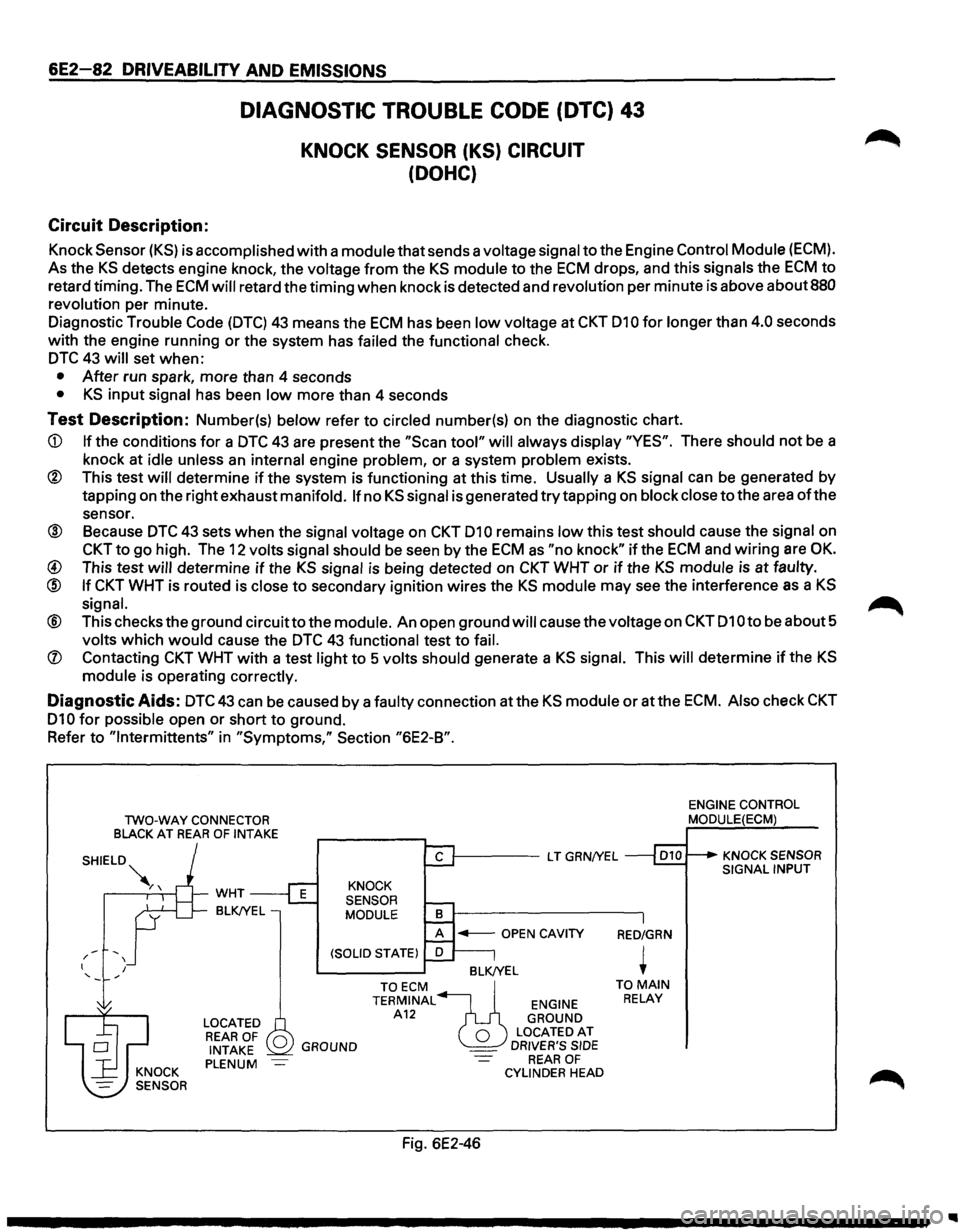
Knock Sensor (KS) is accomplished with a module that sends a voltage signal to the Engine Control Module (ECM).
As the KS detects engine knock, the voltage from the KS module to the ECM drops, and this signals the ECM to
retard timing. The ECM will retard the timing when knock is detected and revolution per minute is above about 880
revolution
per minute.
Diagnostic
Trouble Code (DTC) 43 means the ECM has been low voltage at CKT 010 for longer than 4.0 seconds
with the engine running or the system has
failed the functional check.
DTC 43 will set when:
• After run spark, more than 4 seconds
• KS input signal has been low more than 4 seconds
Test Description: Number(s) below refer to circled number(s) on the diagnostic chart.
CD If the conditions for a DTC 43 are present the "Scan tool" will always display "YES". There should not be a
knock at
idle unless an internal engine problem, or a system problem exists.
® This test will determine if the system is functioning at this time. Usually a KS signal can be generated by
tapping on the right exhaust
manifold. If no KS signal is generated try tapping on block close to the area of the
sensor.
® Because DTC 43 sets when the signal voltage on CKT 010 remains low this test should cause the signal on
CKT to go high. The 12 volts signal should be seen by the ECM as "no knock" if the ECM and wiring are OK.
@ This test will determine if the KS signal is being detected on CKT WHT or if the KS module is at faulty.
@ If CKT WHT is routed is close to secondary ignition wires the KS module may see the interference as a KS
signal. ~
® This checks the ground circuitto the module. An open ground will cause the voltage on CKT 010 to be about 5
volts which would cause the DTC 43 functional test to fail.
(J) Contacting CKT WHT with a test light to 5 volts should generate a KS signal. This will determine if the KS
module is operating correctly.
Diagnostic Aids: DTC43 can be caused by a faulty connection atthe KS module or atthe ECM. Also check CKT
010 for possible open or short to ground.
Refer
to "lntermittents" in "Symptoms," Section "6E2-B".
TWO-WAY CONNECTOR
BLACK AT REAR OF INTAKE
-' / I I
WHT
BLK!YEL
LOCATED REAR OF 0 INTAKE PLENUM
1-----L T GRN/YEL
KNOCK
SENSOR
MODULE
BLK/YEL
GROUND
TOECM ~ TERMINAL ENGINE A12 GROUND
0 LOCATEDAT _ DRIVER'S SIDE REAR OF CYLINDER HEAD
Fig. 6E2-46
RED/GRN
+ TO MAIN RELAY
ENGINE CONTROL MODULE(ECM)
KNOCK SENSOR SIGNAL INPUT