ECO mode ISUZU TROOPER 1995 Workshop Manual
[x] Cancel search | Manufacturer: ISUZU, Model Year: 1995, Model line: TROOPER, Model: ISUZU TROOPER 1995Pages: 1928
Page 14 of 1928
OA-10 GENERAL INFORMATION
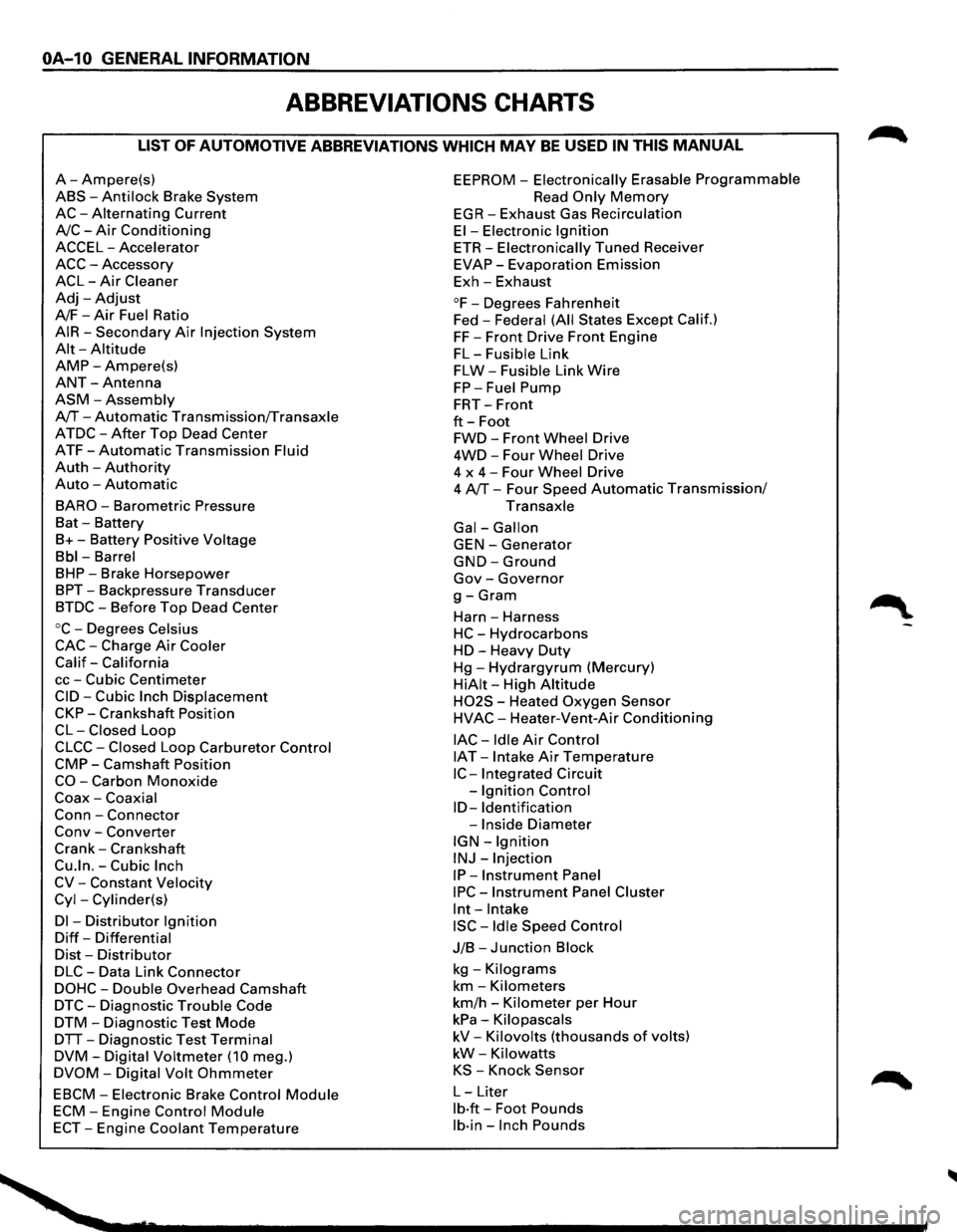
ABBREVIATIONS CHARTS
LIST OF AUTOMOTIVE ABBREVIATIONS WHICH MAY BE USED IN THIS MANUAL
A-Ampere(s)
ABS-Anti lock Brake System
AC-Alternating Current
A/C-Air Conditioning
ACCEL-Accelerator
ACC-Accessory
ACL-Air Cleaner
Adj-Adjust
A/F-Air Fuel Ratio
AIR-Secondary Air Injection System
Alt-Altitude
AMP-Ampere(s)
ANT-Antenna
ASM-Assembly
A/T-Automatic Transmission/Transaxle
ATDC-After Top Dead Center
ATF-Automatic Transmission Fluid
Auth -Authority
Auto -Automatic
BARO-Barometric Pressure
Bat -Battery
B+-Battery Positive Voltage
Bbl-Barrel
BHP-Brake Horsepower
BPT-Backpressure Transducer
BTDC-Before Top Dead Center
oc-Degrees Celsius
CAC-Charge Air Cooler
Calif-California
cc-Cubic Centimeter
CID-Cubic Inch Displacement
CKP-Crankshaft Position
CL-Closed Loop
CLCC-Closed Loop Carburetor Control
CMP-Camshaft Position
CO-Carbon Monoxide
Coax-Coaxial
Conn-Connector
Conv -Converter
Crank-Crankshaft
Cu.ln.-Cubic Inch
CV-Constant Velocity
Cyl-Cylinder(s)
Dl -Distributor Ignition
Diff-Differential
Dist-Distributor
DLC-Data Link Connector
DOHC-Double Overhead Camshaft
DTC-Diagnostic Trouble Code
DTM-Diagnostic Test Mode
DTT-Diagnostic Test Terminal
DVM-Digital Voltmeter (10 meg.)
DVOM-Digital Volt Ohmmeter
EBCM-Electronic Brake Control Module
ECM-Engine Control Module
ECT-Engine Coolant Temperature
EEPROM -Electronically Erasable Programmable
Read Only Memory
EGR-Exhaust Gas Recirculation
El-Electronic Ignition
ETR-Electronically Tuned Receiver
EVAP-Evaporation Emission
Exh-Exhaust
°F-Degrees Fahrenheit
Fed -
Federal (All States Except Calif.)
FF-Front Drive Front Engine
FL-Fusible Link
FLW-Fusible Link Wire
FP-Fuel Pump
FRT-Front
ft-Foot
FWD-Front Wheel Drive
4WD-Four Wheel Drive
4 x
4-Four Wheel Drive
4 A/T-Four Speed Automatic Transmission/
Transaxle
Gal-Gallon
GEN-Generator
GND-Ground
Gov-Governor
g-Gram
Harn -Harness
HC-Hydrocarbons
HD-Heavy Duty
Hg-Hydrargyrum (Mercury)
HiAit-High Altitude
H02S - Heated Oxygen Sensor
HVAC-Heater-Vent-Air Conditioning
lAC-Idle Air Control
IAT -Intake Air Temperature
IC-Integrated Circuit
-
Ignition Control
ID-Identification
-Inside Diameter
IGN-Ignition
INJ-Injection
IP-Instrument Panel
IPC-Instrument Panel Cluster
lnt-Intake
ISC-Idle Speed Control
J/B-Junction Block
kg -Kilograms
km-Kilometers
km/h -Kilometer per Hour
kPa-Kilopascals
kV-Kilovolts (thousands of volts)
kW-Kilowatts
KS -Knock Sensor
L-Liter
lb·ft-Foot Pounds
lb·in-Inch Pounds
Page 73 of 1928
AIR CONDITIONING 1 B -19
ON-VEHICLE SERVICE
GENERAL REPAIR PROCEDURE
Precautions for Replacement or Repair of Air
Conditioning Parts
There are certain procedures, practices and pre
cautions
that should be followed when servicing air
conditioning systems:
• Keep your work area clean.
•
Always wear safety goggle and protective gloves
when working on refrigerant systems.
• Beware of the danger of carbon monoxide fumes
caused by running the engine.
• Beware of discharged refrigerant in enclosed or
improperly ventilated garages.
• Always disconnect the negative battery cable and
discharge and recover the refrigerant
whenever
repairing the air conditioning system.
• When discharging and recovering the refrigerant,
do not allow refrigerant to discharge too fast; it
will draw compressor oil out of the system.
• Keep moisture and contaminants out of the sys
tem.
When disconnecting or removing any lines
or parts, use plugs or caps to close the fittings
immediately.
Never remove the caps or plugs until the lines or
parts are reconnected or installed.
•
When disconnecting or reconnecting the lines,
use
two wrenches to support the line fitting, to
prevent from twisting or other damage.
• Always install new 0-rings whenever a connec
tion is disassembled.
• Before connecting any hoses or lines, apply new
specified compressor oil to the 0-rings.
• When removing and replacing any parts which
require discharging the refrigerant circuit, the
operations described in
this section must be per
formed in the following sequence:
1. Use the J-39500 (ACR4
: HFC-134a Refrigerant
Recovery/Recycling/Recharging/System)
or
equivalent to thoroughly discharge and re
cover
the refrigerant.
2. Remove and replace the defective part.
3.
After evacuation, charge the air conditioning
system and check for leaks.
Repair of Refrigerant Leaks
Refrigerant Line Connections
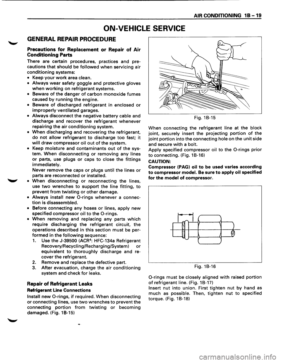
Install new 0-rings, if required. When disconnecting
or connecting lines, use two wrenches to prevent the
connecting
portion from twisting or becoming
damaged. (Fig. 1 B-15) Fig.
18-15
When connecting the refrigerant
line at the block
joint, securely insert the projecting portion of the
joint portion into the connecting hole on the unit side
and secure
with a bolt.
Apply specified compressor oil to the 0-rings prior
to connecting. (Fig. 18-16)
CAUTION:
Compressor (PAGI oil to be used varies according
to compressor model. Be sure to apply oil specified
for the model of compressor.
~1;1_ ~ ' .. J '--......
Fig. 18-16
0-rings must be closely aligned with raised portion
of refrigerant line. (Fig. 18-17)
Insert nut into union. First tighten nut by hand as
much as possible. Then, tighten nut to specified
torque. (Fig. 1 8-18)
Page 89 of 1928
COMPRESSOR OVERHAUL 1 D - 1
SECTION 10
COMPRESSOR OVERHAUL
CONTENTS
General Description . . . . . . . . . . . . . . . . . . . . . 1 D-1
Diagnosis . . . . . . . . . . . . . . . . . . . . . . . . . . . . . 1
D-2
General Information . . . . . . . . . . . . . . . . . . . . 1 D-3
Compressor Oil . . . . . . . . . . . . . . . . . . . . . . 1 D-3
Service Procedures . . . . . . . . . . . . . . . . . . . . . 1D-5
Magnetic Clutch Assembly . . . . . . . . . . . . . 1 D-5
Main Data and Specifications . . . . . . . . . . . . . 1 D-8
General Specifications . . . . . . . . . . . . . . . . . 1 D-8
Torque Specifications . . . . . . . . . . . . . . . . . 1 D-8
Special Tools . . . . . . . . . . . . . . . . . . . . . . . . . . 1D-9
GENERAL DESCRIPTION
When servicing the compressor, keep dirt or foreign
material from getting on or into the compressor
parts and system. Clean tools and a clean work area
are
important for proper service. The compressor
connections and the outside of the compressor
should be cleaned before any "On-Vehicle" repair,
or before removal of the compressor. The parts must
be kept clean at all times and any parts to be
reassembled
should be cleaned with Trichloro
ethane, naphtha, kerosene, or equivalent solvent,
and
dried with dry air. Use only lint free cloths to
wipe parts.
The
operations described below are based on bench
overhaul
with compressor removed from the
vehicle, except as noted. They have been prepared
in
order of accessibility of the components. When
the compressor is removed from the vehicle for
servicing, the oil remaining in the compressor
should be discarded and new compressor oil added
to the compressor.
Magnetic clutch assembly repair procedures require
that the system be discharged of refrigerant. (Refer
to Section 1 B for "REFRIGERANT RECOVERY".)
Compressor malfunction will appear in one of four
ways: noise, seizure, leakage or low discharge
pressure. Resonant
compressor noises are not
cause for alarm; however, irregular noise or rattles
may indicate broken parts or excessive clearances
due to wear. To check seizure, de-energize the
magnetic clutch and check to see if the drive plate
can be rotated.
If rotation is impossible, the com
pressor is seized. Low discharge pressure may be
due to a faulty internal seal of the compressor, or a
restriction in the compressor.
Low discharge pres
sure
may also be due to an insufficient refrigerant
charge
or a restriction elsewhere in the system.
These possibilities
should be checked prior to
servicing the compressor. If the compressor is
inoperative,
but is not seized, check to see if current
is being supplied to the magnetic clutch coil
terminals.
This vehicle is equipped with five-vane rotary com
pressor.
The
compressor has vanes built into a rotor which is
mounted on a shaft.
When the shaft rotates, the vanes built into the
cylinder block assembly are opened by centrifugal
force.
This changes the volume of the space formed by the
rotor and cylinder, resulting in the intake and
compression of the refrigerant gas. The discharge
valve and the
valve stopper, which protects the
discharge valve, are
built into the cylinder block
assembly. There is no suction valve but a shaft seal
is
installed between the shaft and head; a trigger
valve, which applies back pressure to the vanes, is
installed in the cylinder block and a refrigerant gas
temperature sensor is installed in the front head.
The specified
quantity of compressor oil is contained
in
the compressor to lubricate the various parts
using
the refrigerant gas discharge pressure.
The thermo sensor is installed to the front head of
the compressor to protect it by stopping its
operation when the refrigerant gas is insufficient or
when the temperature get abnormally high.
•OFF ..... 160 ±soc (320.0 ± 9.0°F)
•ON ..... 135 ±soc (275.0 ± 9.0°F)
The oil used in the HFC-134a system compressor
differs from that used in R-12 systems.
Also, compressor
oil to be used varies according to
the compressor model. Be sure to avoid mixing two
or more different types of oil.
If the wrong oil is used, lubrication will be poor and
the compressor will seize or malfunction.
The specified
amount of the compressor oil is
150cc (5.0 fl.oz.).
Page 91 of 1928
COMPRESSOR OVERHAUL 10-3
GENERAL INFORMATION
COMPRESSOR OIL
OIL SPECIFICATION
• The HFC-134a system requires a synthetic
(PAG) compressor oil whereas the R-12 system
requires a
mineral compressor oil. The two oils
must never be mixed.
• Compressor (PAG) oil varies according to com
pressor model. Be sure to use oil specified for
the model of compressor.
• Always use HFC-134a Vane Rotary Type Com
pressor Oil
(AIPDN Part No. 2-90188-301-0)
HANDLING OF OIL
• The oil should be free from moisture, dust,
metal powder, etc.
• Do not mix with other oil.
•
The water content in the oil increases when
exposed to the air. After use, seal oil from air
immediately.
(HFC-134a Vane Rotary Compressor Oil absorbs
moisture very easily.)
•
The compressor oil must be stored in steel
containers, not in plastic containers.
COMPRESSOR OIL CHECK
The oil used to lubricate the compressor is circul
ating with the refrigerant.
Whenever replacing any component of the system
or a large amount of gas leakage occurs, add oil to
maintain the original amount of oil.
Oil Capacity.
Capacity
total in system 150cc (5.0 fl.oz.)
Compressor (Service
parts)
charging amount 15 0cc (5
·0
fl.oz.)
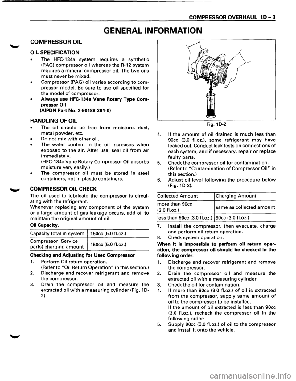
Checking and Adjusting for Used Compressor
1. Perform Oil return operation.
(Refer to "Oil Return Operation" in this section.)
2. Discharge and recover refrigerant and remove
the compressor.
3. Drain the compressor oil and measure the
extracted oil with a measuring cylinder (Fig. 1 D-
2).
Fig. 1D-2
4. If the amount of oil drained is much less than
90cc (3.0 fl.oz.), some refrigerant may have
leaked out. Conduct leak tests on connections of
each system, and if necessary, repair or replace
faulty parts.
5. Check the compressor oil for contamination.
(Refer to "Contamination of Compressor Oil" in
this section.)
6. Adjust oil level following the procedure below
(Fig. 1 D-3).
Collected Amount
more than 90cc
(3.0 fl.oz.)
Charging Amount
same as collected amount
less than 90cc (3.0 fl.oz.) 90cc (3.0 fl.oz.)
7. Install the compressor, then evacuate, charge
and
perform oil return operation.
8. Check system operation.
When it is impossible to perform oil return oper
ation, the compressor oil should be checked in the
following order:
1. Discharge and recover refrigerant and remove
the compressor.
2. Drain the compressor oil and measure the
extracted oil with a measuring cylinder.
3. Check the oil for contamination.
4. If more than 90cc (3.0 fl.oz.) of oil is extracted
from the compressor, supply same amount of
oil to the compressor to be installed.
If
the amount of oil extracted is less than 90cc
(3.0 fl.oz.),
recheck the compressor oil in the
following order:
5. Supply 90cc (3.0 fl.oz.) of oil to the compressor
and install it onto the vehicle.
Page 142 of 1928
381 - 4 POWER STEERING GEAR AND PUMP
ON-VEHICLE SERVICE
MAINTENANCE
The hydraulic system should be kept clean and fluid
level in the reservoir should be checked at regular
intervals
and fluid added when required. Refer to
"MAINTENANCE AND LUBRICATION" in section OB
ofthe manual for type offluid to be used and intervals
for filling.
If the system contains some dirt, flush it as detailed
later
in this section. If it is exceptionally dirty, both the
pump and the gear must be completely disassembled
before further usage.
All tubes, hoses, and fittings should be inspected for
leakage at regular intervals. Fittings must be tight.
Make sure the clips, clamps and supporting tubes and
hoses are in
place and properly secured.
Power steering hoses and lines must not be twisted,
kinked or tightly bent. Air in the system will cause
spongy action and noisy operation. When a hose is
disconnected
or when fluid is lost, for any reason, the
system must be bled after refilling. Refer to "Bleeding
the Power Steering System" in this section.
FLUID LEVEL
1. Run the engine until the power steering fluid
reaches normal operating temperature, about
55°C (130°F), then shut the engine off.
2. Check the level of fluid in the reservoir.
3. If the fluid level is low, add power steering fluid
as specified in "MAINTENANCE AND LUBRI
CATION" in Section OB to the proper level and
install the receiver cap.
4. When checking the fluid level after the steering
system has been serviced,
air must be bled from
the system. Refer to "Bleeding the Power
Steering
System" in this section.
BLEEDING THE POWER STEERING
SYSTEM
When a power steering pump or gear has been
installed, or an oil line has been disconnected, the air
that has entered the system must be bled out before
the vehicle is operated. If air is allowed to remain in
the power steering fluid system, noisy and
unsatisfactory operation of the system may result.
BLEEDING PROCEDURE
When bleeding the system, and any time fluid is
added
to the power steering system, be sure to use
only power steering fluid as specified in
"MAINTENANCE AND LUBRICATION" in section OB.
1. Fill the pump fluid reservoir to the proper level
and let the fluid settle for at least two minutes.
2. Start the engine and let it run for a few seconds.
Do
not turn the steering wheel. Then turn the
engine off.
3. Add fluid if necessary.
4. Repeat the above procedure until the fluid level
remains constant after running the engine.
5. Raise the front end of the vehicle so that the
wheels are off the ground.
6. Start the engine. Slowly turn the steering wheel
right and left, lightly contacting the wheel stops.
7. Add power steering fluid if necessary.
8. Lower the vehicle and turn the steering wheel
slowly from lock to lock.
9. Stop the engine. Check the fluid level and refill
as required.
10.
If the fluid is extremely foamy, allow the vehicle
to stand a few minutes and repeat the above
procedure.
~ INSPECT
• Belt for tightness.
• Pulley for looseness or damage. The pulley
should not wobble with the engine running.
• Hoses so they are not touching any other parts
of the vehicle.
• Fluid level
and fill to the proper level.
FLUSHING THE POWER STEERING
SYSTEM
1. Raise the front end of the vehicle off the ground
until the wheels are free to turn.
2. Remove the fluid return line at the pump inlet
connector and plug the connector port on the
pump.
Position the line toward a large container to
catch the draining fluid.
3. While running the engine at idle, fill the reservoir
with new power steering fluid. Turn the steering
wheel in both directions. DO NOT contact wheel
stops or hold the wheel in a corner, or fluid will
stop and the pump will be in pressure relief mode.
A sudden
overflow from the reservoir may
develop if the wheel is held at a stop.
4. Install all the lines and hoses. Fill the system with
new power steering fluid and bleed the system
as described in "Bleeding The Power Steering
System". Operate the engine for about 15
minutes.
Remove the
pump return line at the pump inlet
and plug the connection on the pump. While
refilling the reservoir, check the draining fluid for
contamination. If foreign material is still evident,
replace all lines, disassemble and clean or replace
the power steering system components. Do not
re-use any drained power steering fluid.
~
~
Page 329 of 1928
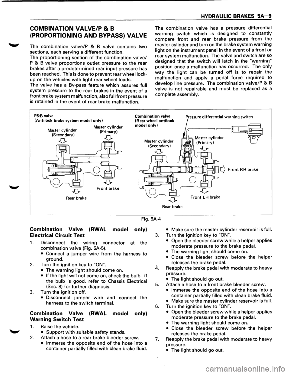
COMBINATION VALVE/P & B
(PROPORTIONING AND BYPASS) VALVE
The combination valve/P & B valve contains two
sections, each serving a different function.
The proportioning section
of the combination valve/
P & B valve proportions outlet pressure to the rear
brakes after a predetermined rear
input pressure has
been reached. This is done to prevent rear
wheel lock
up on the vehicles with light rear wheel loads.
The valve has a By-pass feature which assures full
system pressure to the rear brakes in the event of a
front brake system malfunction, also full front pressure
is retained in the event
of rear brake malfunction.
HYDRAULIC BRAKES 5A 9
The combination valve has a pressure differential
warning switch which is designed to constantly
compare front and rear brake pressure
from the
master
cylinder and turn on the brake system warning
light on the instrument panel in the event of a front or
rear system malfunction. The valve and switch are so
designed that the switch
will latch in the "warning"
position once a malfunction has occurred. The only
way the light can be turned off is to repair the
malfunction and
apply a pedal force required to
develop line pressure. The combination valve/P & B
valve is not repairable and must be replaced as a
complete assembly.
P&B valve
(Antilock brake system model only)
Master cylinder (Primary)
Combination valve (Rear wheel antilock model only)
Pressure differential warning switch
Master
cylinder (Secondary)
..(> ..(> Master cylinder (Secondary) Master
cylinder
(Primary)
..(> ..(>
Front brake
Rear brake
Combination Valve
Electrical Circuit Test (RWAL
model
Fig. 5A-4
only)
1.
2.
3.
Disconnect the wmng connector at the
combination
valve (Fig. 5A-5).
• Connect a jumper wire from the harness to
ground.
Turn the ignition key to
"ON".
•
The warning light should come on.
• If the light will not come on, check the bulb. If
the bulb is good, refer to Chassis Electrical
(Sec.
8) for further diagnosis.
Turn the ignition off.
• Disconnect jumper wire and connect the
harness to the switch
terminal.
Combination Valve (RWAL model only)
Warning
Switch Test
1. Raise the vehicle.
• Support
with suitable safety stands.
2. Attach a hose to a rear brake bleeder screw.
• Immerse the opposite end of the hose into a
container
partially filled with clean brake fluid.
3.
4.
5.
6.
7.
¢ Front RH brake
Front LH brake
Rear brake
• Make sure the master cylinder reservoir is full.
Turn the ignition key to "ON".
• Open
the bleeder screw while a helper applies
moderate pressure to the brake pedal.
•
The warning light should come on.
• Close the bleeder screw before the helper
releases
the brake pedal.
Reapply the brake pedal with moderate to heavy
pressure.
• The light should go out.
Attach a hose
to a front brake bleeder screw.
• Immerse the opposite end of the hose into a
container
partially filled with clean brake fluid.
• Make sure the master cylinder reservoir is full.
Turn the ignition key to "ON".
• Open
the bleeder screw while a helper applies
moderate pressure to the brake pedal.
•
The warning light should come on.
• Close the bleeder screw before the helper
releases
the brake pedal.
Reapply
the brake pedal with moderate to heavy
pressure.
• The light should go out.
Page 343 of 1928
BRAKE BOOSTER SYSTEM 5A 1-1
SECTION 5A1
BRAKE BOOSTER SYSTEM
W CAUTION:
• Fasteners are an important attaching part in that they could affect performance of vital parts and systems,
and/or could result in major repair expense. They must be replaced with one of the same part number or with
an equivalent part if replacement becomes necessary. Do not use replacement parts of lesser quality or
substitute design. Torque values must be used as specified during reassembly to assure proper retention of
these parts.
CONTENTS
General Description . . . . . . . . . . . . . . . . . . . SA 1-1 Vacuum Booster .................... SA1-6
Diagnosis ..................... See Section SA Main Data and Specifications ........... SA1-6
On-Vehicle Service ................... SA1-2 General Specifications ............... SA1-6
Vacuum Booster Assembly ........... SA1-2 Torque Specifications ................ SA1-6
Exterior Components ................ SA1-4 Special Tools ......................... SA1-7
Unit Repair .......................... SA1-6
GENERAL DESCRIPTION
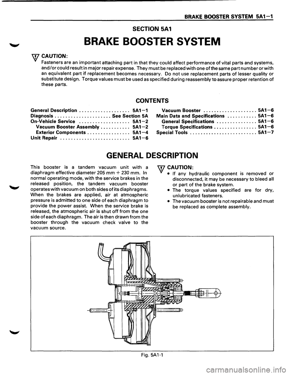
This booster is a tandem vacuum unit with a
diaphragm effective diameter
205 mm + 230 mm. In
normal operating mode, with the service brakes in the
released position, the tandem vacuum booster
operates
with vacuum on both sides of its diaphragms.
When the brakes are
applied, air at atmospheric
pressure is admitted
to one side of each diaphragm to
provide the power assist. When the service brake is
released, the atmospheric air is shut off from the one
side
of each diaphragm. The air is then drawn from the
booster through the vacuum check
valve to the
vacuum source.
W CAUTION:
• If any hydraulic component IS removed or
disconnected, it may be necessary to bleed all
or part of the brake system.
Fig.
5A1-1
• The torque values specified are for dry,
unlubricated fasteners.
• The vacuum booster is not repairable and must
be replaced as complete assembly.
Page 411 of 1928
4-WHEEL ANTILOCK BRAKE SYSTEM (ABS) 5A4-1
SECTION 5A4
'--' 4-WHEEL ANTILOCK BRAKE SYSTEM (ABS)
CAUTION
All
brake attaching fasteners are an important attaching part in that they could affect performance of
vital parts and systems, and/or could result in major repair expense. They must be replaced with one
of the same part number or with an equivalent part if replacement becomes necessary. Do not use
replacement parts
of lesser quality or substitute design. Torque values must be used as specified
during reassembly to assure proper retention of these parts.
CONTENTS
General Description .................... 5A4-3
System Components ................. 5A4-3
Electronic Brake
Control Module ·
(EBCM) .......................... 5A4-3
Hydraulic Unit ...................... 5A4-3
ABS Warning Light .................. 5A4-4
Wheel
Speed Sensor ................. 5A4-4
G-Sensor
........................... 5A4-4
Normal and Antilock Braking .......... 5A4-4
Brake Pedal Travel
................... 5A4-4
Abbreviation ........................ 5A4-4
Diagnosis
............................. 5A4-5
General
Information ................. 5A4-5
ABS
System Service Precautions ....... 5A4-5
Computer System Service
Precautions
....................... 5A4-5
General Service Precautions
........... 5A4-5
Note on lntermittents ................ 5A4-6
Test Driving ABS Complaint Vehicles ... 5A4-6
II ABS11 Warning Light ................ 5A4-6
Normal Operation ................... 5A4-6
Basic
Diagnostic Flow Chart ........... 5A4-7
Basic
Inspection Procedure ............ 5A4-8
TECH 1
TOOL. ......................... 5A4-10
1. What can be done with TECH 1 ...... 5A4-10
2. How to Use TECH 1 ................ 5A4-11
3. Explanation of Modes .............. 5A4-15
Mode FO: Data List ................... 5A4-16
Mode F2: Trouble Code ............... 5A4-18
Mode F3: Snapshot .................. 5A4-19
Mode F4: Clear Code ................. 5A4-20
Mode F5: Actuator Test ............... 5A4-21
Mode F6: Wheel Sensors ............. 5A4-31
Pin-Out Checks ........................ 5A4-33
Circuit Diagram ..................... 5A4-34
Part Location ....................... 5A4-37
Symptom Diagnosis .................... 5A4-38
CHART A-1 1) ABS Works Frequently
but Vehicle does not Decelerate ...... 5A4-39
CHART TA-1 1) ABS Works Frequently
but Vehicle does not Decelerate ...... 5A4-40
CHART A-2 2) Uneven Braking Occurs
while ABS Works .................. 5A4-41
CHART TA-2 2) Uneven Braking Occurs
while ABS Works .................. 5A4-42
CHART A-3, T A-3 3) The Wheels are
Locked
........................... 5A4-43
CHART A-4 4) Brake Pedal Feel is
Abnormal ........................ 5A4-44
CHART A-5 , T A-5 5) Braking Sound
(from Hydraulic Unit) is Heard while
not Braking ....................... 5A4-45
Diagnosis by 11 ABS11 Warning Light
Illumination Pattern .................. 5A4-46
Diagnostic Trouble Codes (DTCs) ....... 5A4-47
1. How to Display and Erase DTCs ... 5A4-47
2. Diagnostic Trouble Codes ........ 5A4-49
CHART B-1 With the Key in the ON
Position (before Starting the Engine),
Warning Light (W /L) is not
•
Actuated ........................ 5A4-50
CHART B-2 II ABSII Light Flashes
Twice with Key ON ................ 5A4-51
CHART B-3 EBCM Abnormality (Diagnostic
Trouble Code 14) .................. 5A4-52
CHART B-4 Power Voltage Drop (Diagnostic
Trouble Code 15) .................. 5A4-53
CHART B-5 G-Sensor Circuit (Diagnostic
Trouble Code 21) .................. 5A4-54
CHART B-6 Brake Switch Trouble
(Diagnostic Trouble Code 22) ........ 5A4-55
CHART B-7 Abnormal Transmission Input
(A/T Modei)(Diagnostic Trouble
Code 23) ......................... 5A4-56
CHART B-7 Abnormal Transmission Input
(M/T Modei)(Diagnostic Trouble
Code 23) ......................... 5A4-57
CHART B-8 Hydraulic Unit (HU) Pump
Motor and Motor Relay Circuit
(Diagnostic Trouble Code 32) ........ 5A4-58
CHART B-9 Solenoid Valve Abnormality
(Diagnostic Trouble Code 41, 42,
& 44) ............................ 5A4-59
CHART B-10 Valve Relay Abnormality
(Diagnostic Trouble Code 45) ........ 5A4-60
Page 441 of 1928
4-WHEEL ANTILOCK BRAKE SYSTEM (ABS) 5A4-31
MODE F6: WHEEL SENSORS
When conducting the wheel sensor test, note the following:
1) Accelerate vehicle only slightly above 20 km/h (12 mph).
2) When this speed is attained, put transmission into neutral and allow vehicle to coast to a halt. (Parking
brake may be engaged slightly.)
3) When vehicle is at a standstill, actuate either foot brake or parking brake.
When the
wheel speed sensor test is being performed, the output or speed value of all four sensors is
monitored
by TECH 1. When the output of wheel sensors becomes too low to convert into speed value, the
last known vehicle speed is displayed and the values are fixed. If wheel sensors are normal, it is at the
vehicle speed
of 5 km/h (3 mph) or less that their output is lost. Therefore, if all the fixed speed values are
less than 5 km/h (3 mph), the wheel sensors are normal. If one or more of the four speed values is more
than 5 km/h
(3 mph), it suggests that the following abnormalities have occurred to the sensor(s):
1. Excess gap between the sensor and sensor rotor.
2. Broken or damaged sensor rotor teeth.
3. Momentary open in sensor harness.
Page 457 of 1928
4-WHEEL ANTILOCK BRAKE SYSTEM (ASS) 5A4-47
DIAGNOSTIC TROUBLE CODES (DTCs)
When the warning light in the meter remains ON, the EBCM stores the fault identification and disables the
.........,.. ABS.
1. How to display and erase DTCs:
NOTE:
• If DTCs are not displayed, harness BB 14 may be disconnected. Repair the harness and try DTC
display again.
• DTCs can be displayed also by TECH 1. For further details, see "MODE F2: TROUBLE CODE" in this
section.
(1)
How to start DTC display:
• Confirm
that the vehicle has come to a complete stop (with the wheels standing still) and that the
brake pedal is not depressed. (Unless these two condition are satisfied, DTC display cannot be
started.)
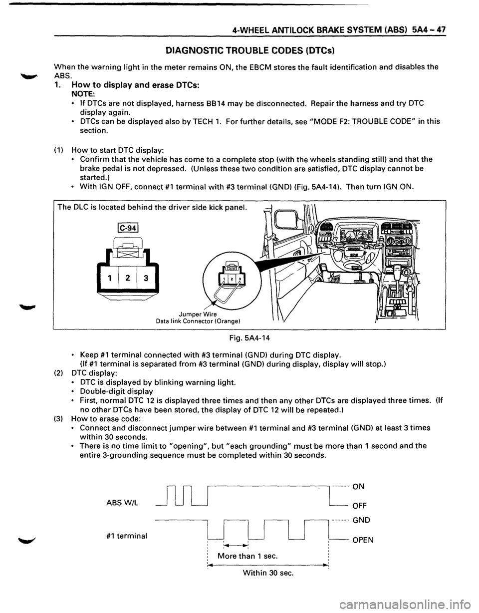
• With IGN OFF, connect #1 terminal with #3 terminal (GND) (Fig. 5A4-14). Then turn IGN ON.
The DLC is located behind the driver side kick panel.
1 2 3
Jumper Wire Data link Connector (Orange}
Fig. 5A4-14
• Keep #1 terminal connected with #3 terminal (GND) during DTC display.
(If
#1 terminal is separated from #3 terminal (GND) during display, display will stop.)
(2) DTC display:
•
DTC is displayed by blinking warning light.
•
Double-digit display
•
First, normal DTC 12 is displayed three times and then any other DTCs are displayed three times. (If
no other DTCs have been stored, the display of DTC 12 will be repeated.)
(3) How to erase code:
• Connect and disconnect jumper wire between #1 terminal and #3 terminal (GND) at least 3 times
within 30 seconds.
• There is no time limit to "opening", but "each grounding" must be more than 1 second and the
entire 3-grounding sequence must be completed within 30 seconds.
ABS W/L
#1 terminal
r---------------, ------ON
More than 1 sec.
OFF
.--------, ------ GND
OPEN
' ,._ _________ ,_:
Within 30 sec.