display ISUZU TROOPER 1995 User Guide
[x] Cancel search | Manufacturer: ISUZU, Model Year: 1995, Model line: TROOPER, Model: ISUZU TROOPER 1995Pages: 1928
Page 434 of 1928
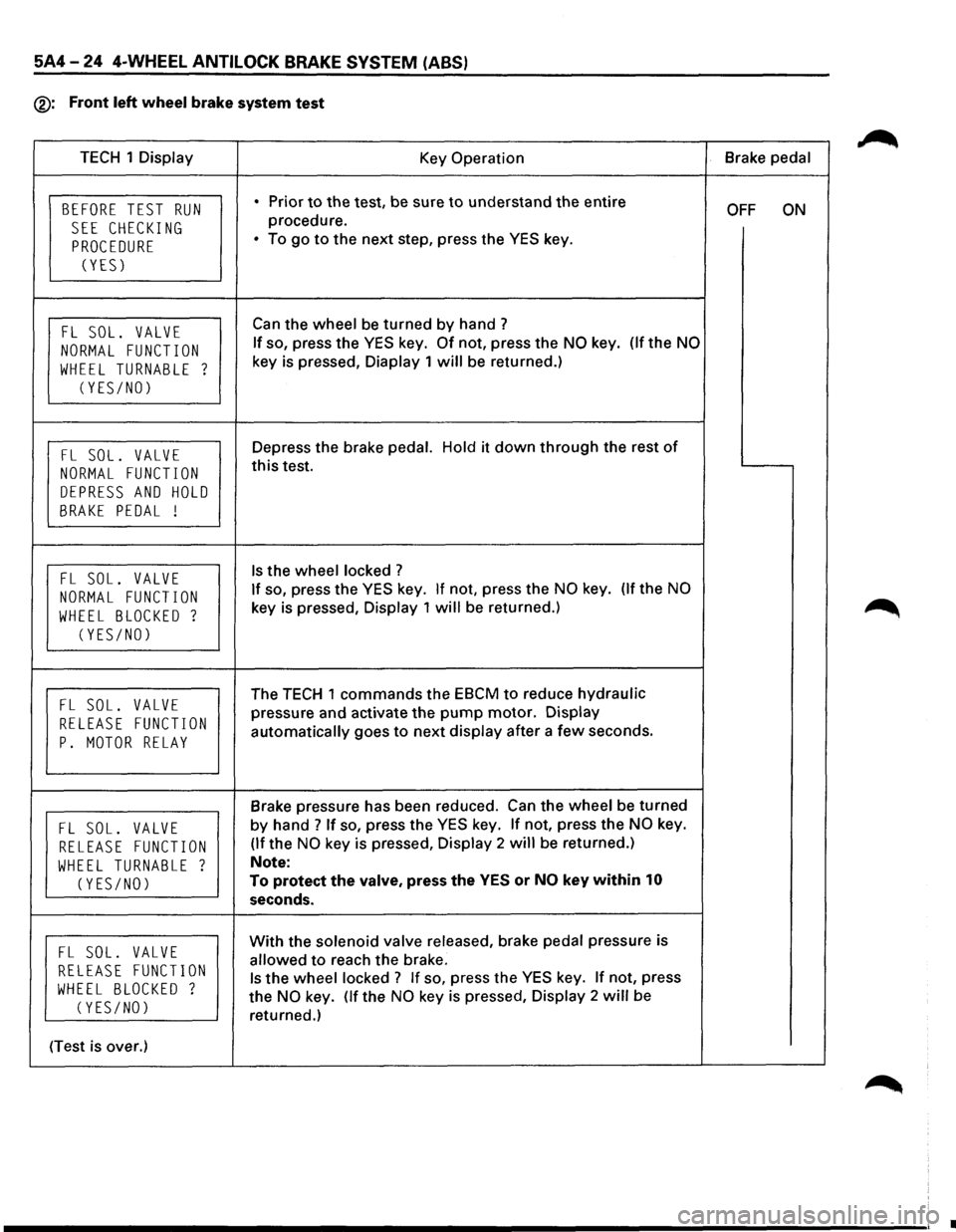
5A4-24 4-WHEEL ANTILOCK BRAKE SYSTEM (ABS)
®: Front left wheel brake system test
TECH 1 Display
Key Operation Brake
pedal
BEFORE TEST RUN • Prior to the test, be sure to understand the entire OFF ON
SEE CHECKING procedure.
PROCEDURE • To go to the next step, press the YES key.
(YES)
FL SOL. VALVE Can the wheel be turned by hand?
NORMAL FUNCTION If so, press the YES key. Of not, press the NO key. (lfthe NO
WHEEL TURNABLE ? key is pressed, Diaplay 1 will be returned.)
(YES/NO)
FL SOL. VALVE Depress the brake pedal. Hold it down through the rest of
NORMAL FUNCTION this test.
DEPRESS AND HOLD
BRAKE PEDAL !
FL SOL. VALVE Is the wheel locked ?
NORMAL FUNCTION If so, press the YES key. If not, press the NO key. (If the NO
WHEEL BLOCKED ? key is pressed, Display 1 will be returned.)
(YES/NO)
FL SOL. VALVE The TECH 1 commands the EBCM to reduce hydraulic
RELEASE FUNCTION pressure and activate the pump motor. Display
p. MOTOR RELAY automatically goes to next display after a few seconds.
Brake pressure has been reduced. Can the wheel be turned
FL SOL. VALVE by hand ? If so, press the YES key. If not, press the NO key.
RELEASE FUNCTION (If the NO key is pressed, Display 2 will be returned.)
WHEEL TURNABLE ? Note:
(YES/NO) To protect the valve, press the YES or NO key within 10
seconds.
FL SOL. VALVE With the solenoid valve released, brake pedal pressure is
RELEASE FUNCTION allowed to reach the brake.
WHEEL BLOCKED ? Is the wheel locked ? If so, press the YES key. If not, press
(YES/NO) the NO key. (If the NO key is pressed, Display 2 will be
returned.)
(Test is over.)
•
Page 435 of 1928
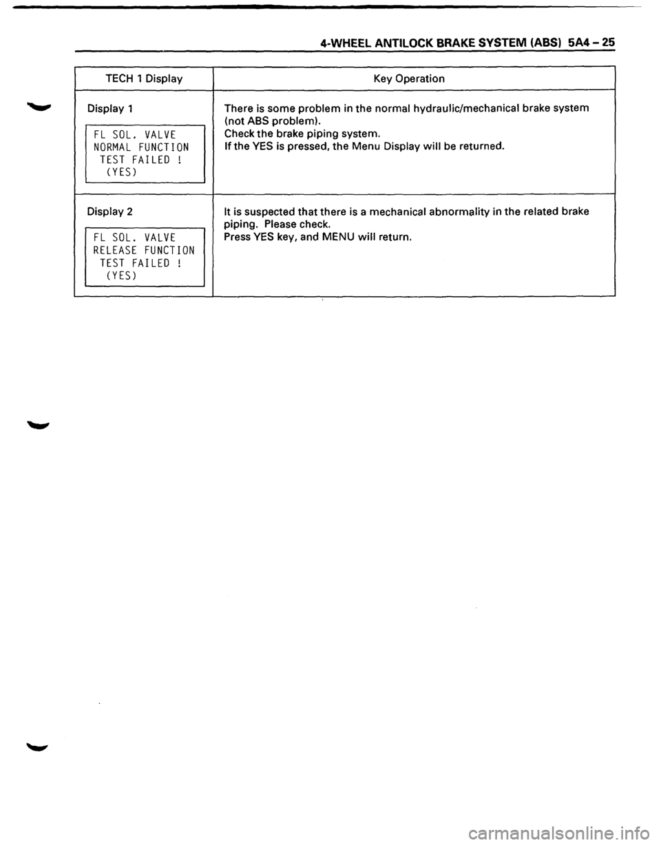
4-WHEEL ANTILOCK BRAKE SYSTEM (ABS) 5A4-25
TECH 1 Display Key Operation
Display 1 There is some problem in the normal hydraulic/mechanical brake system
(not
ABS problem).
FL SOL. VALVE Check the brake piping system.
NORMAL FUNCTION If the YES is pressed, the Menu Display will be returned.
TEST FAILED !
(YES)
Display 2 It is suspected that there is a mechanical abnormality in the related brake
piping.
Please check.
FL SOL. VALVE Press YES key, and MENU will return.
RELEASE FUNCTION
TEST FAILED !
C YES)
Page 436 of 1928
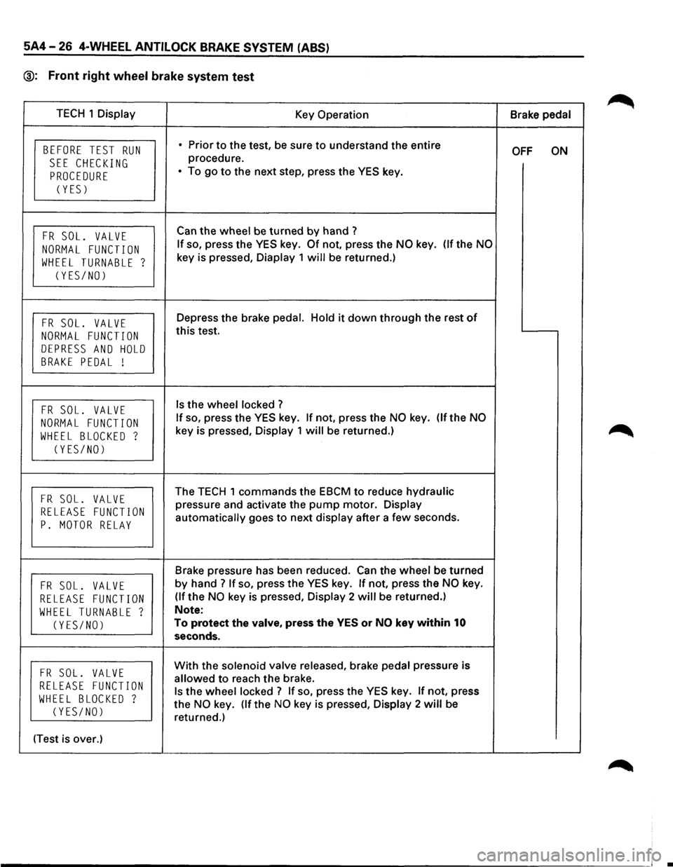
5A4-26 4-WHEEL ANTILOCK BRAKE SYSTEM (ABS)
@: Front right wheel brake system test
TECH 1 Display
Key Operation Brake pedal
BEFORE TEST RUN • Prior to the test, be sure to understand the entire OFF ON
SEE CHECKING procedure.
PROCEDURE • To go to the next step, press the YES key.
(YES)
FR SOL. VALVE Can the wheel be turned by hand ?
NORMAL FUNCTION If so, press the YES key. Of not, press the NO key. (If the NO
WHEEL TURNABLE ? key is pressed, Diaplay 1 will be returned.)
(YES/NO)
FR SOL. VALVE Depress the brake pedal. Hold it down through the rest of
NORMAL FUNCTION this test.
DEPRESS AND HOLD
BRAKE PEDAL !
FR SOL. VALVE Is the wheel locked ?
NORMAL FUNCTION If so, press the YES key. If not, press the NO key. (If the NO
WHEEL BLOCKED ? key is pressed, Display 1 will be returned.)
(YES/NO)
FR SOL. VALVE The TECH 1 commands the EBCM to reduce hydraulic
RELEASE FUNCTION pressure and activate the pump motor. Display
P. MOTOR RELAY automatically goes to next display after a few seconds.
Brake pressure has been reduced.
Can the wheel be turned
FR SOL. VALVE by hand? If so, press the YES key. If not, press the NO key.
RELEASE FUNCTION (If the NO key is pressed, Display 2 will be returned.)
WHEEL TURNABLE ? Note:
(YES/NO) To protect the valve, press the YES or NO key within 10
seconds.
FR SOL. VALVE With the solenoid valve released, brake pedal pressure is
RELEASE FUNCTION allowed to reach the brake.
WHEEL BLOCKED ? Is the wheel locked? If so, press the YES key. If not, press
(YES/NO) the NO key. (If the NO key is pressed, Display 2 will be
returned.)
(Test is over.)
•
Page 437 of 1928
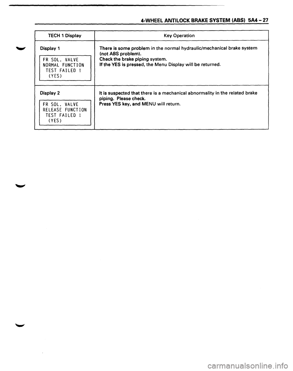
4-WHEEL ANTI LOCK BRAKE SYSTEM (ABS) 5A4-27
TECH 1 Display Key Operation
Display 1 There
is some problem in the normal hydraulic/mechanical brake system
(not
ABS problem).
FR SOL. VALVE Check the brake piping system.
NORMAL FUNCTION If the YES is pressed, the Menu Display will be returned.
TEST FAILED
!
(YES)
Display 2 It is suspected that there is a mechanical abnormality in the related brake
piping. Please check.
FR SOL. VALVE Press YES key, and MENU will return.
RELEASE FUNCTION
TEST FAILED
!
(YES)
Page 438 of 1928
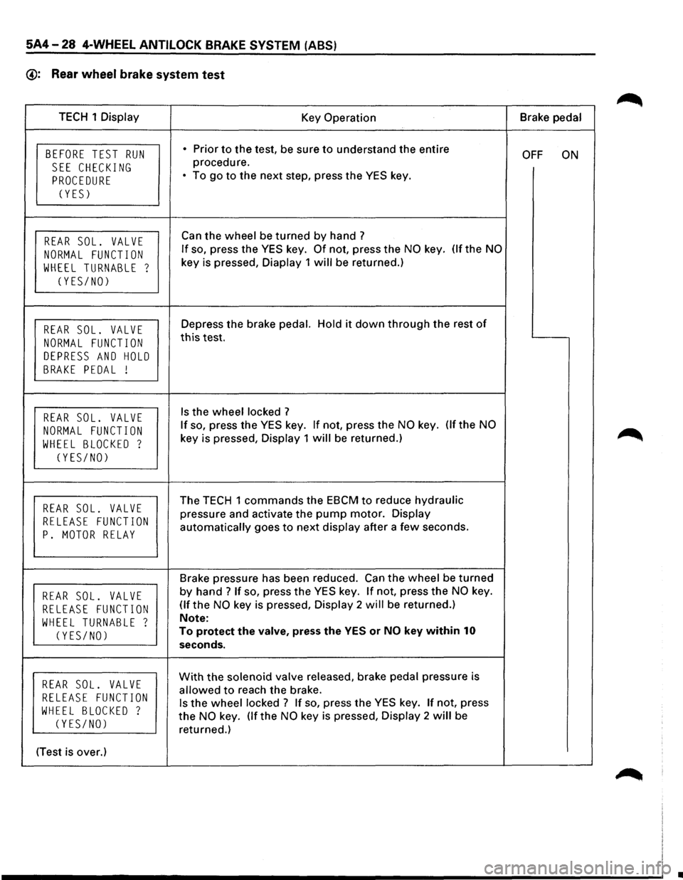
5A4-28 4-WHEEL ANTILOCK BRAKE SYSTEM (ABS)
@: Rear wheel brake system test
TECH 1 Display
Key Operation Brake
pedal
BEFORE TEST RUN • Prior to the test, be sure to understand the entire OFF ON
SEE CHECKING procedure.
PROCEDURE • To go to the next step, press the YES key.
(YES)
REAR SOL. VALVE Can the wheel be turned by hand ?
NORMAL FUNCTION If so, press the YES key. Of not, press the NO key. (If the NO
WHEEL TURNABLE ? key is pressed, Diaplay 1 will be returned.)
(YES/NO)
REAR SOL. VALVE Depress the brake pedal. Hold it down through the rest of
NORMAL FUNCTION this test.
DEPRESS AND HOLD
BRAKE PEDAL !
REAR SOL. VALVE Is the wheel locked ?
NORMAL FUNCTION If so, press the YES key. If not, press the NO key. Of the NO
WHEEL BLOCKED ? key is pressed, Display 1 will be returned.)
(YES/NO)
REAR SOL. VALVE The TECH 1 commands the EBCM to reduce hydraulic
RELEASE FUNCTION pressure and activate the pump motor. Display
P. MOTOR RELAY automatically goes to next display after a few seconds.
Brake pressure has been reduced. Can
the wheel be turned
REAR SOL. VALVE by hand ? If so, press the YES key. If not, press the NO key.
RELEASE FUNCTION (If the NO key is pressed, Display 2 will be returned.)
WHEEL TURNABLE ? Note:
(YES/NO) To protect the valve, press the YES or NO key within 10
seconds.
REAR SOL. VALVE With the solenoid valve released, brake pedal pressure is
RELEASE FUNCTION allowed to reach the brake.
WHEEL BLOCKED ? Is the wheel locked ? If so, press the YES key. If not, press
(YES/NO) the NO key. (If the NO key is pressed, Display 2 will be
returned.)
(Test is over.)
•
Page 439 of 1928
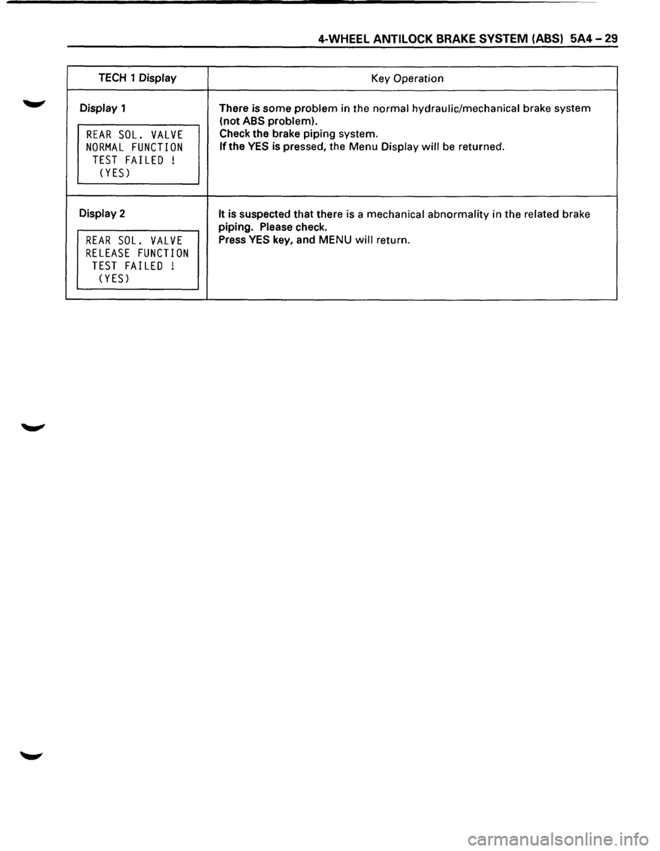
4-WHEEL ANTILOCK BRAKE SYSTEM (ABS) 5A4-29
TECH 1 Display
Key Operation
Display 1
There is some
problem in the normal hydraulic/mechanical brake system
(not
ABS problem).
REAR SOL. VALVE Check the brake piping system.
NORMAL FUNCTION lfthe YES is pressed, the Menu Display will be returned.
TEST FAILED !
(YES)
Display 2 It is suspected that there is a mechanical abnormality in the related brake
piping. Please check.
REAR SOL. VALVE Press YES key, and MENU will return.
RELEASE FUNCTION
TEST FAILED !
(YES)
Page 440 of 1928
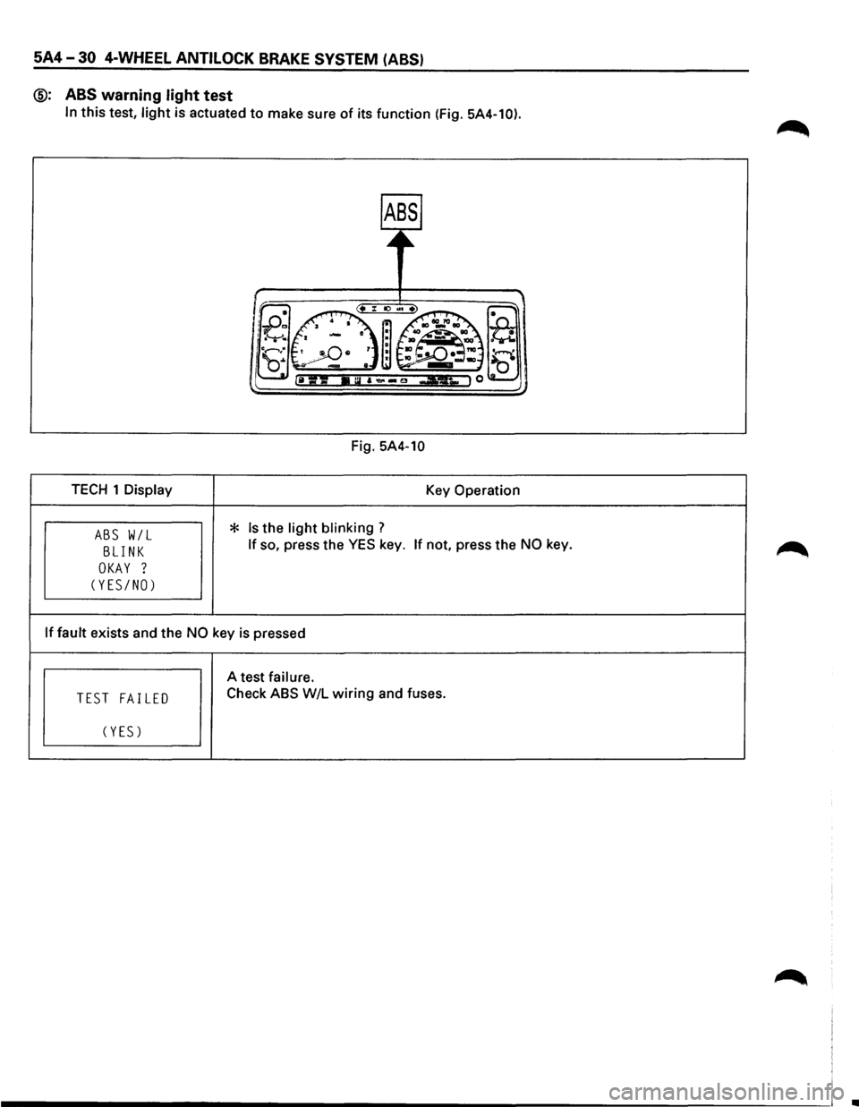
5A4-30 4-WHEEL ANTILOCK BRAKE SYSTEM (ABS)
@: ABS
warning light test
In this test, light is actuated to make sure of its function (Fig. 5A4-10).
Fig. 5A4-10
TECH 1 Display
Key Operation
Is the light blinking ? ABS W/L * BLINK If so, press the YES key. If not, press the NO key.
OKAY ?
(YES/NO)
If
fault exists and the NO key is pressed
A test failure.
TEST FAILED Check ABS W/L wiring and
fuses.
(YES)
i _______________________________________________________________________ \
! •
Page 441 of 1928
4-WHEEL ANTILOCK BRAKE SYSTEM (ABS) 5A4-31
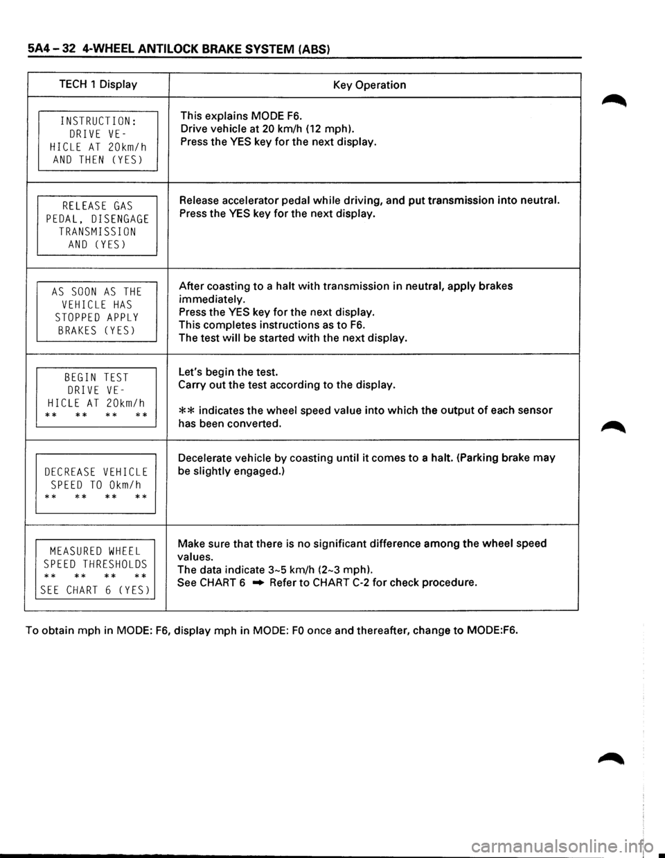
MODE F6: WHEEL SENSORS
When conducting the wheel sensor test, note the following:
1) Accelerate vehicle only slightly above 20 km/h (12 mph).
2) When this speed is attained, put transmission into neutral and allow vehicle to coast to a halt. (Parking
brake may be engaged slightly.)
3) When vehicle is at a standstill, actuate either foot brake or parking brake.
When the
wheel speed sensor test is being performed, the output or speed value of all four sensors is
monitored
by TECH 1. When the output of wheel sensors becomes too low to convert into speed value, the
last known vehicle speed is displayed and the values are fixed. If wheel sensors are normal, it is at the
vehicle speed
of 5 km/h (3 mph) or less that their output is lost. Therefore, if all the fixed speed values are
less than 5 km/h (3 mph), the wheel sensors are normal. If one or more of the four speed values is more
than 5 km/h
(3 mph), it suggests that the following abnormalities have occurred to the sensor(s):
1. Excess gap between the sensor and sensor rotor.
2. Broken or damaged sensor rotor teeth.
3. Momentary open in sensor harness.
Page 442 of 1928
5A4-32 4-WHEEL ANTI LOCK BRAKE SYSTEM (ABS)
TECH 1 Display Key Operation
INSTRUCT I ON: This explains MODE F6.
DRIVE VE-Drive vehicle at 20 km/h (12 mph).
HICLE AT 20km/h Press the YES key for the next display.
AND THEN (YES)
RELEASE GAS Release accelerator pedal while driving, and put transmission into neutral.
PEDAL, DISENGAGE Press the YES key for the next display.
TRANSMISSION
AND (YES)
AS SOON AS THE After coasting to a halt with transmission in neutral, apply brakes
VEHICLE HAS immediately.
STOPPED APPLY Press the YES key for the next display.
BRAKES (YES) This completes instructions as to F6.
The test will be started with the next display.
BEGIN TEST Let's begin the test.
DRIVE VE-Carry out the test according to the display.
HICLE AT 20km/h ** indicates the wheel speed value into which the output of each sensor ** ** ** ** has been converted.
Decelerate vehicle by coasting until it comes to a halt. (Parking brake may
DECREASE VEHICLE be slightly engaged.)
SPEED TO Okm/h
** ** ** **
MEASURED WHEEL Make sure that there is no significant difference among the wheel speed
SPEED THRESHOLDS values.
** **
** ** The
data indicate 3-5 km/h (2-3 mph).
SEE CHART 6 (YES) See CHART 6 .. Refer to CHART C-2 for check procedure.
To obtain mph in
MODE: F6, display mph in MODE: FO once and thereafter, change to MODE:F6.
Page 456 of 1928
5A4-46 4-WHEEL ANTILOCK BRAKE SYSTEM (ABS)
DIAGNOSIS BY II ABS,
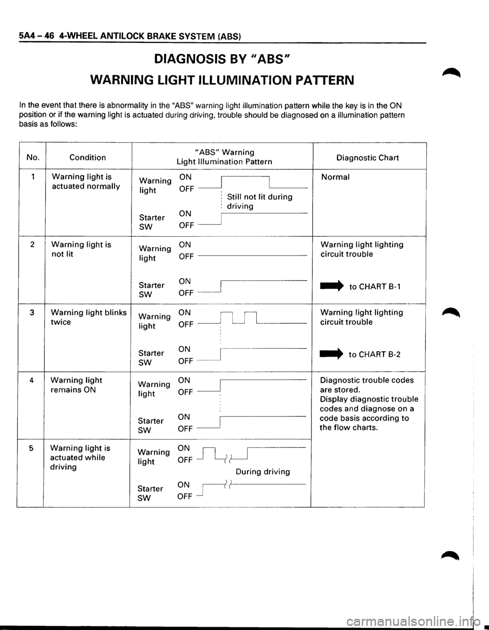
WARNING LIGHT ILLUMINATION PATTERN
In the event that there is abnormality in the "ASS" warning light illumination pattern while the key is in the ON
position or if the warning light is actuated during driving, trouble should be diagnosed on a illumination pattern
basis as
follows:
No.
Condition "ABS" Warning Diagnostic Chart
Light Illumination Pattern
1 Warning light is ON Normal Warning I I actuated normally light OFF ' , Still not lit during
Starter ON : driving
sw OFF
2 Warning light is
Warning ON Warning light lighting
not lit light OFF circuit trouble
ON .... to CHART 8-1
Starter I sw OFF
3 Warning light blinks Warning ON Warning light lighting
twice light OFF circuit trouble
:
ON ... to CHART
B-2
Starter
sw OFF
4 Warning light ON Diagnostic trouble codes Warning J remains ON light OFF are
stored.
Display diagnostic trouble ' codes and diagnose on a
Starter
ON I code basis according to
sw OFF the flow charts.
5 Warning light is ON~ Warning actuated while light OFF driving During driving
ONr(l Starter
sw OFF