display ISUZU TROOPER 1995 Owner's Guide
[x] Cancel search | Manufacturer: ISUZU, Model Year: 1995, Model line: TROOPER, Model: ISUZU TROOPER 1995Pages: 1928
Page 714 of 1928
6E2-18 DRIVEABILITV AND EMISSIONS
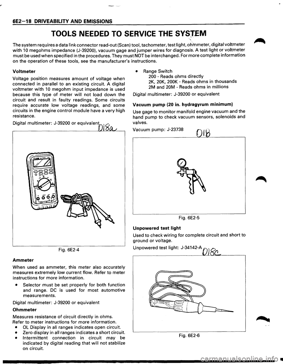
TOOLS NEEDED TO SERVICE THE SVSJEM
The system requires a data link connector read-out (Scan) tool, tachometer, test light, ohmmeter, digital voltmeter
with 10 megohms impedance (J-39200), vacuum gage and jumper wires for diagnosis. A test light or voltmeter
must be used when specified in the procedures. They must NOT be interchanged. For more complete information
on the operation
of these tools, see the manufacturer's instructions.
Voltmeter
Voltage position measures amount of voltage when
connected in
parallel to an existing circuit. A digital
voltmeter
with 10 megohm input impedance is used
because this type
of meter will not load down the
circuit and
result in faulty readings. Some circuits
require accurate
low voltage readings, and some
circuits in the engine
control module have a very high
resistance.
Digital multimeter: J-39200 or equivalent
Fig. 6E2-4
Ammeter
When used as ammeter, this meter also accurately
measures extremely low current flow. Refer to meter
instructions
for more information.
• Selector must be set properly for both function
and range.
DC is used for most automotive
measurements.
Digital multimeter: J-39200 or equivalent
Ohmmeter
Measures resistance of circuit directly in ohms.
Refer to meter instructions
for more information.
• OL Display in all ranges indicates open circuit.
• Zero display in all ranges indicates a short circuit.
• Intermittent connection in circuit may be
indicated by digital reading that will not stabilize
on circuit.
• Range Switch
200 -Reads ohms
directly
2K, 20K, 200K -Reads ohms in thousands
2M and 20M -Reads ohms in
millions
Digital multimeter:
J-39200 or equivalent
Vacuum pump (20 in. hydragyrum minimum)
Use gage to monitor manifold engine vacuum and the
hand pump to check vacuum sensors,
solenoids and
valves.
Vacuum pump: J-23738
Fig. 6E2-5
Unpowered test light
Used to check wiring for complete circuit and short to
ground
or voltage.
Unpowered test light: J-34142-A
Fig. 6E2-6
•
Page 730 of 1928
6E2-34 DRIVEABILITY AND EMISSIONS
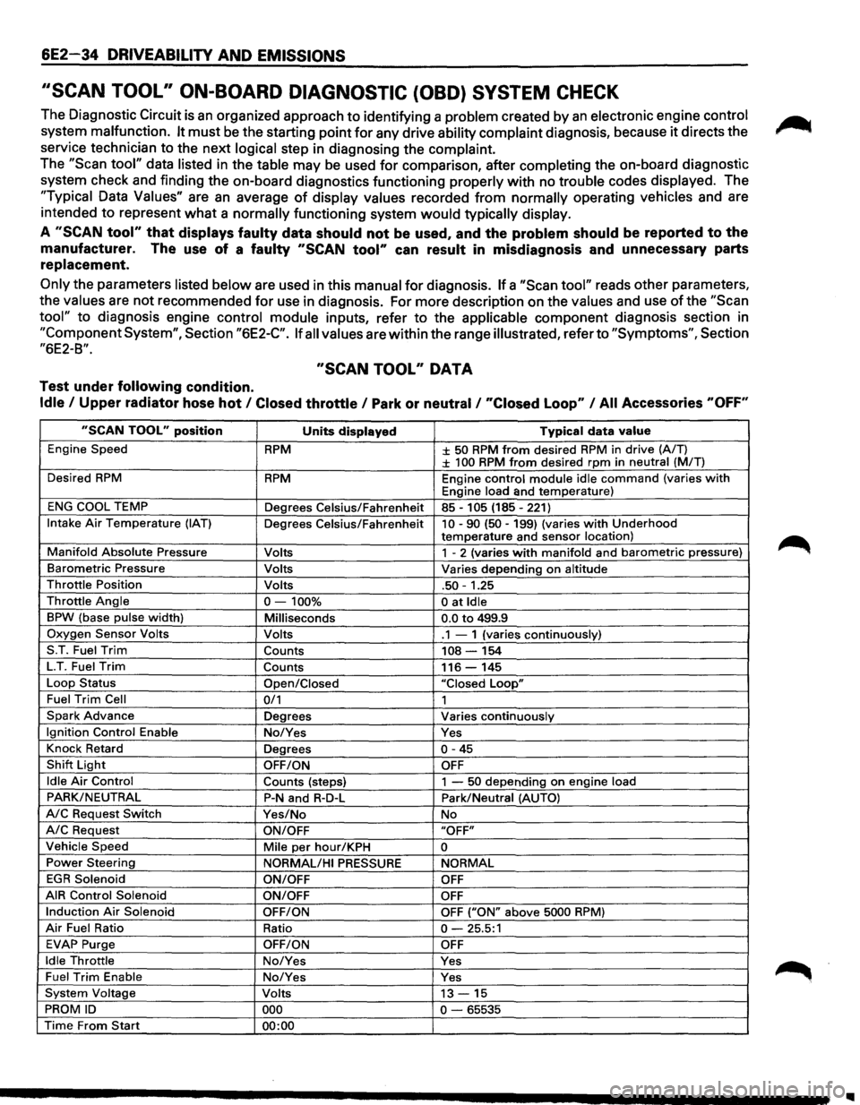
''SCAN TOOL" ON-BOARD DIAGNOSTIC (OBD) SYSTEM CHECK
The Diagnostic Circuit is an organized approach to identifying a problem created by an electronic engine control
system malfunction. It must be the starting point for any drive ability complaint diagnosis, because it directs the
service technician to the next
logical step in diagnosing the complaint.
The "Scan tool" data listed in the table may be used for comparison, after completing the on-board diagnostic
system check and finding the on-board diagnostics functioning
properly with no trouble codes displayed. The
"Typical Data Values" are an average of display values recorded from normally operating vehicles and are
intended
to represent what a normally functioning system would typically display.
A "SCAN tool" that displays faulty data should not be used, and the problem should be reported to the
manufacturer. The use of a faulty "SCAN tool" can result in misdiagnosis and unnecessary parts
replacement.
Only the parameters listed below are used in this manual for diagnosis. If a "Scan tool" reads other parameters,
the
values are not recommended for use in diagnosis. For more description on the values and use of the "Scan
tool" to diagnosis engine control module inputs, refer to the applicable component diagnosis section in
"Component System", Section "6E2-C". If all values are within the range illustrated, refer to "Symptoms", Section
"6E2-B".
"SCAN TOOL" DATA
Test under following condition.
Idle I Upper radiator hose hot I Closed throttle I Park or neutral I "Closed Loop" I All Accessories "OFF"
"SCAN TOOL" position Units displayed Typical data value
Engine Speed RPM ± 50 RPM from desired RPM in drive (A/T) ± 100 RPM from desired rpm in neutral (MIT)
Desired
RPM RPM Engine control module idle command (varies with Engine load and temperature)
ENG COOL TEMP
Degrees Celsius/Fahrenheit 85-105 (185-221)
Intake Air Temperature (IAT) Degrees Celsius/Fahrenheit 10-90 (50-199) (varies with Underhood
temperature and sensor location)
Manifold Absolute Pressure Volts 1 - 2 (varies with manifold and barometric pressure)
Barometric Pressure Volts Varies depending on altitude
Throttle Position Volts .50-1.25
Throttle Angle 0-100% 0 at Idle
BPW (base pulse width) Milliseconds 0.0 to 499.9
Oxygen Sensor Volts Volts .1 - 1 (varies continuously)
S.T. Fuel
Trim Counts 108-154
LT. Fuel Trim Counts 116-145
Loop Status
Open/Closed "Closed Loop"
Fuel Trim Cell 0/1 1
Spark Advance Degrees Varies continuously
Ignition Control Enable No/Yes Yes
Knock Retard
Degrees
0-45
Shift Light OFF/ON OFF
Idle Air Control
Counts (steps) 1 -50 depending on engine load
PARK/NEUTRAL P-N and R-D-L Park/Neutral (AUTO)
A/C Request Switch Yes/No No
A/C Request ON/OFF "OFF"
Vehicle Speed
Mile per hour/KPH 0
Power Steering
NORMAL/HI PRESSURE NORMAL
EGR Solenoid
ON/OFF OFF
AIR Control Solenoid
ON/OFF OFF
Induction Air Solenoid OFF/ON OFF ("ON" above 5000 RPM)
Air Fuel Ratio Ratio 0-25.5:1
EVAP Purge OFF/ON OFF
Idle Throttle No/Yes Yes
Fuel Trim Enable No/Yes Yes
System Voltage Volts 13-15
PROM ID 000 0-65535
Time From Start 00:00
Page 733 of 1928
DRIVEABILITY AND EMISSIONS 6E2-37
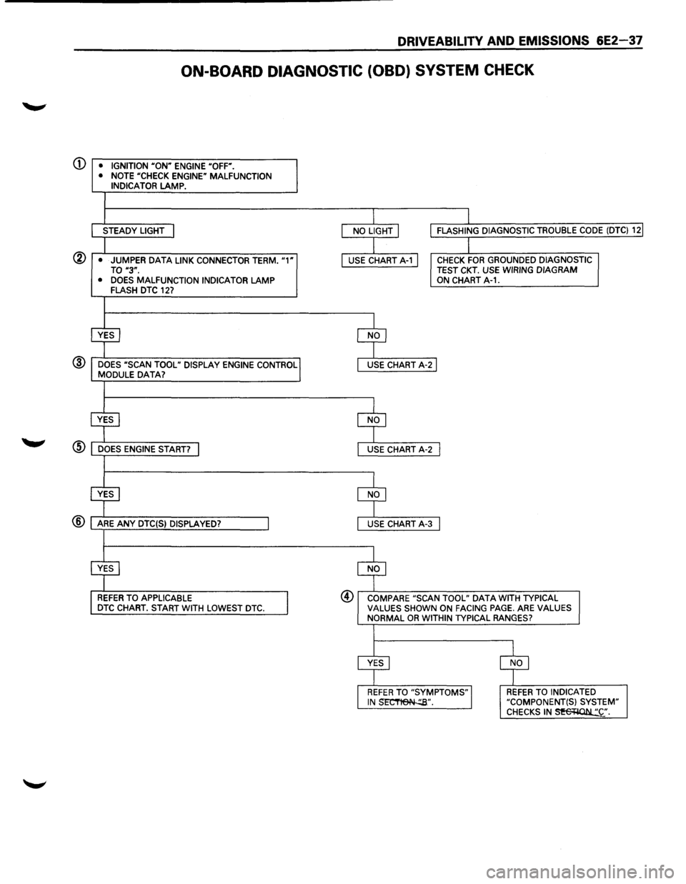
ON-BOARD DIAGNOSTIC (OBD) SYSTEM CHECK
(j) • IGNITION "ON" ENGINE "OFF".
• NOTE "CHECK ENGINE" MALFUNCTION INDICATOR LAMP.
STEADY LIGHT
@ • JUMPER DATA LINK CONNECTOR TERM. "1" TO "3".
• DOES MALFUNCTION INDICATOR LAMP FLASH DTC 127
@ DOES "SCAN TOOL" DISPLAY ENGINE CONTROL MODULE DATA?
REFER TO APPLICABLE DTC CHART. START WITH LOWEST DTC.
CHECK FOR GROUNDED DIAGNOSTIC TEST CKT. USE WIRING DIAGRAM ON CHART A-1.
@ COMPARE "SCAN TOOL" DATA WITH TYPICAL VALUES SHOWN ON FACING PAGE. ARE VALUES NORMAL OR WITHIN TYPICAL RANGES?
REFER TO INDICATED "COMPONENT(S) SYSTEM" CHECKS IN~·.
Page 755 of 1928
Q)
®
DRIVEABILITV AND EMISSIONS 6E2-59
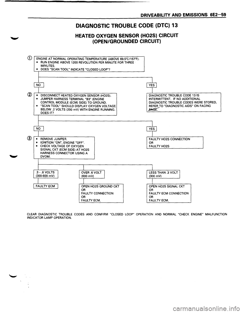
DIAGNOSTIC TROUBLE CODE {DTC) 13
HEATED OXYGEN SENSOR (H02S) CIRCUIT
(OPEN/GROUNDED CIRCUIT)
ENGINE AT NORMAL OPERATING TEMPERATURE (ABOVE 69SC/157'F). • RUN ENGINE ABOVE 1200 REVOLUTION PER MINUTE FOR THREE MINUTES.
• DOES "SCAN TOOL" INDICATE "CLOSED LOOP"?
~ cvf
• DISCONNECT HEATED OXYGEN SENSOR (H02S). DIAGNOSTIC
TROUBLE CODE 13 IS
• JUMPER HARNESS TERMINAL "B3" (ENGINE INTERMITIENT. IF NO
ADDITIONAL
CONTROL MODULE (ECM) SIDE) TO GROUND. DIAGNOSTIC TROUBLE CODES WERE STORED,
• "SCAN TOOL" SHOULD DISPLAY OXYGEN VOLTAGE REFER TO "DIAGNOSTIC AIDS" ON FACING
BELOW .2 VOLTS (200 mV) WITH ENGINE RUNNING. ~ DOES IT?
~ cvf
• REMOVE JUMPER.
FAULTY H02S CONNECTION
• IGNITION "ON", ENGINE "OFF". OR • CHECK VOLTAGE OF OXYGEN FAULTY H02S SIGNAL CKT (ECM SIDE) AT H02S HARNESS CONNECTOR USING A DVOM.
I I .3-.6 VOLTS I (300-600 mV) OVER .6 VOLT J (600 mV) LESS THAN .3 VOLT J (300 mV)
l I FAULTY ECM j OPEN H02S GROUND CKT OPEN H02S SIGNAL CKT OR OR FAULTY CONNECTION FAULTY ECM CONNECTION OR OR FAULTY ECM. FAULTY ECM.
CLEAR
DIAGNOSTIC TROUBLE CODES AND CONFIRM "CLOSED LOOP" OPERATION AND NORMAL "CHECK ENGINE" MALFUNCTION
INDICATOR LAMP OPERATION.
Page 756 of 1928
6E2-60 DRIVEABILITY AND EMISSIONS
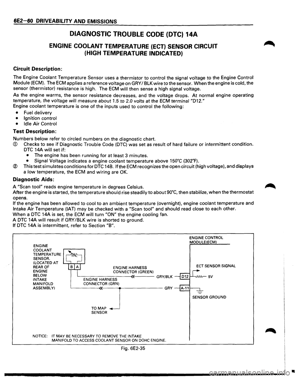
DIAGNOSTIC TROUBLE CODE (DTC) 14A
ENGINE COOLANT TEMPERATURE (ECT) SENSOR CIRCUIT
(HIGH
TEMPERATURE INDICATED)
Circuit Description:
The Engine Coolant Temperature Sensor uses a thermistor to control the signal voltage to the Engine Control
Module
(ECM). The ECM applies a reference voltage on GRY I 8LK wire to the sensor. When the engine is cold, the
sensor (thermistor) resistance is high. The
ECM will then sense a high signal voltage.
As the engine warms, the sensor resistance decreases, and the voltage drops. At normal engine operating
temperature, the
voltage will measure about 1.5 to 2.0 volts at the ECM terminal "D12."
Engine coolant temperature is one of the inputs used to control the following:
• Fuel delivery
• Ignition control
• Idle
Air Control
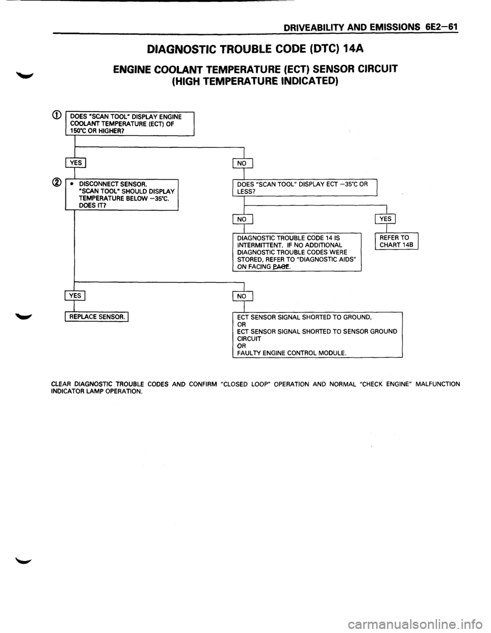
Test Description:
Numbers below refer to circled numbers on the diagnostic chart.
CD Checks to see if Diagnostic Trouble Code (DTC) was set as result of hard failure or intermittent condition.
DTC 14A will set if:
• The engine has been running for at least 3 minutes.
• Signal Voltage indicates a engine coolant temperature above 15o•c (302.F).
® This test simulates conditions for DTC 148. lfthe ECM recognizes the open circuit (high voltage), and displays
a low temperature, the ECM and wiring are OK.
Diagnostic Aids:
A "Scan tool" reads engine temperature in degrees Celsius.
After the engine is started, the temperature should rise steadily to about so·c, then stabilize, when the thermostat
opens.
If the engine has been allowed to cool to an ambient temperature (overnight), engine coolant temperature and
Intake Air Temperature (IAT) may be checked with a "Scan tool" and should read close to each other.
When a
DTC 14A is set, the ECM will turn "ON" the engine cooling fan.
A
DTC 14A will result if GRY /8LK wire is shorted to ground.
If DTC 14A is intermittent, refer to Section "8".
ENGINE
COOLANT
TEMPERATURE SENSOR. (LOCATED AT REAR OF ENGINE
BELOW
INTAKE
MANIFOLD
ASSEMBLY) ENGINE
HARNESS CONNECTOR(GREEN) L----------<~---GRY/BLK ENGINE HARNESS
CONNECTOR (GRN)
L__ ___ T_O~M(~A-P-~-~-------GRY
SENSOR
NOTICE: IT
MAY BE NECESSARY TO REMOVE THE INTAKE
MANIFOLD TO ACCESS COOLANT SENSOR ON DOHC ENGINE.
Fig. 6E2-35
ENGINE CONTROL MODULE(ECM)
ECT SENSOR SIGNAL
SENSOR GROUND
•
Page 757 of 1928
DRIVEABILITV AND EMISSIONS 6E2-61
DIAGNOSTIC TROUBLE CODE (DTC) 14A
ENGINE COOLANT TEMPERATURE (ECT) SENSOR CIRCUIT
(HIGH TEMPERATURE INDICATED)
(D DOES •scAN TOOL• DISPLAY ENGINE COOLANT TEMPERATURE (ECT) OF 150"C OR HIGHER?
@ • DISCONNECT SENSOR. ·sCAN TOOL • SHOULD DISPLAY TEMPERATURE BELOW -3s•c. DOES IT?
DIAGNOSTIC TROUBLE CODE 141S INTERMITTENT. IF NO ADDITIONAL DIAGNOSTIC TROUBLE CODES WERE STORED, REFER TO "DIAGNOSTIC AIDS" ON FACING fA81:.
ECT SENSOR SIGNAL SHORTED TO GROUND, OR ECT SENSOR SIGNAL SHORTED TO SENSOR GROUND CIRCUIT OR FAULTY ENGINE CONTROL MODULE.
CLEAR DIAGNOSTIC TROUBLE CODES AND CONFIRM "CLOSED LOOP" OPERATION AND NORMAL "CHECK ENGINE" MALFUNCTION INDICATOR LAMP OPERATION.
Page 758 of 1928
6E2~62 DRIVEABILITY AND EMISSIONS
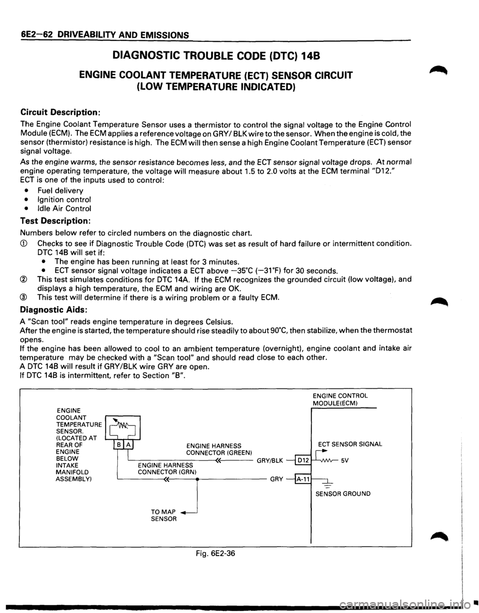
DIAGNOSTIC TROUBLE CODE (DTC) 148
ENGINE COOLANT TEMPERATURE (ECT) SENSOR CIRCUIT
(LOW TEMPERATURE INDICATED)
Circuit Description:
The Engine Coolant Temperature Sensor uses a thermistor to control the signal voltage to the Engine Control
Module (ECM). The ECM applies a reference voltage on GRY I 8LK wire to the sensor. When the engine is cold, the
sensor (thermistor) resistance
is high. The ECM will then sense a high Engine Coolant Temperature (ECT) sensor
signal
voltage.
As the engine warms, the sensor resistance becomes less, and the ECT sensor signal voltage drops. At normal
engine operating temperature, the voltage will measure about 1.5 to 2.0 volts at the ECM terminal "012."
ECT is one of the inputs used to control:
• Fuel delivery
• Ignition control
• Idle
Air Control
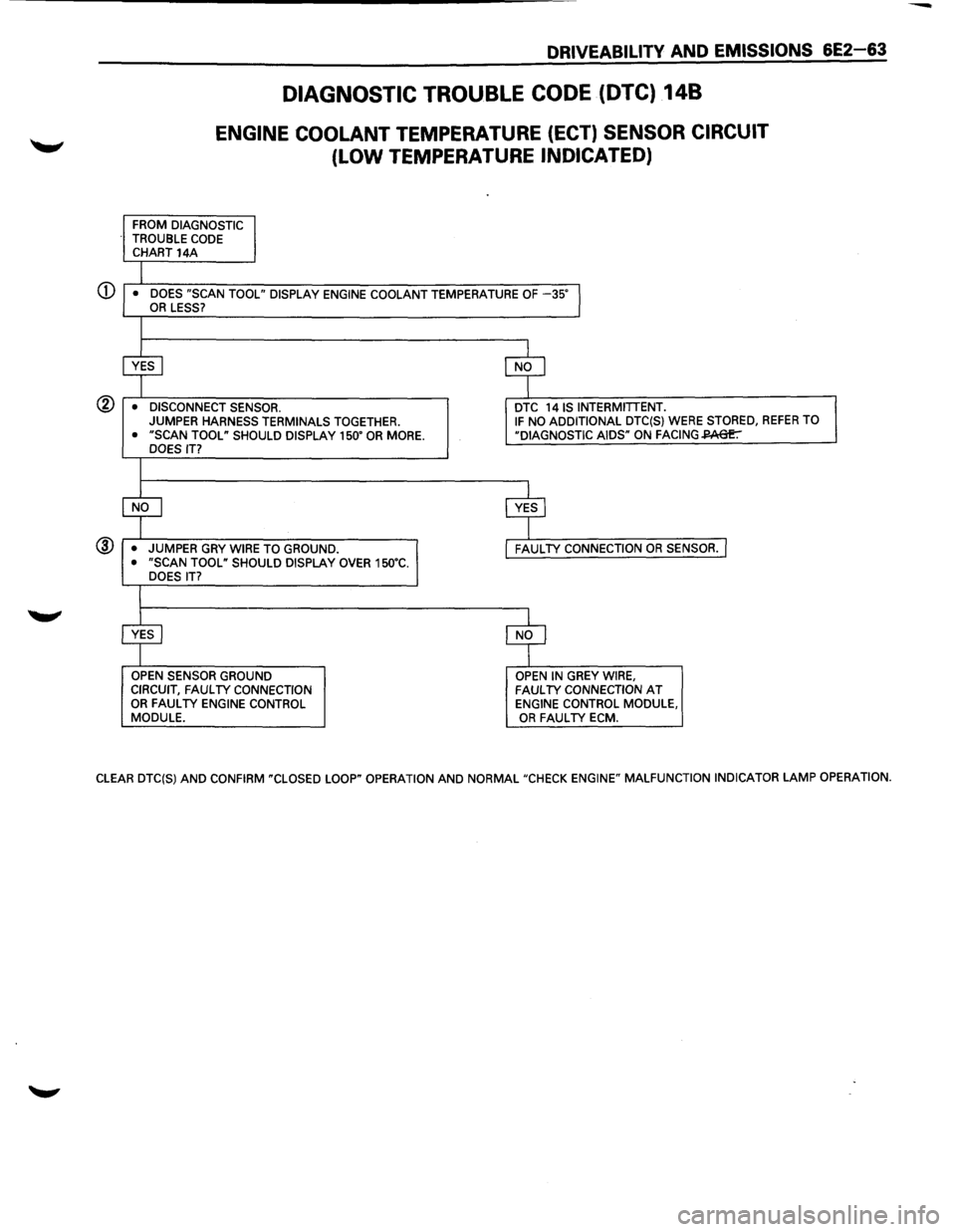
Test Description:
Numbers below refer to circled numbers on the diagnostic chart.
CD Checks to see if Diagnostic Trouble Code (DTC) was set as result of hard failure or intermittent condition.
DTC 148 will set if:
• The engine has been running at least for 3 minutes.
• ECT sensor signal voltage indicates a ECT above -35°C (-31 OF) for 30 seconds.
® This test simulates conditions for DTC 14A. If the ECM recognizes the grounded circuit (low voltage), and
displays a high temperature, the ECM and wiring are OK.
@ This test will determine if there is a wiring problem or a faulty ECM.
Diagnostic Aids:
A "Scan tool" reads engine temperature in degrees Celsius.
After the engine is started, the temperature should rise steadily to about 90°C, then stabilize, when the thermostat
opens.
If the engine has been allowed to cool to an ambient temperature (overnight), engine coolant and intake air
temperature may be checked
with a "Scan tool" and should read close to each other.
A
DTC 148 will result if GRY/8LK wire GRY are open.
If DTC 148 is intermittent, refer to Section "8".
ENGINE
COOLANT
TEMPERATURE SENSOR.
(LOCATED AT REAR OF ENGINE
BELOW
INTAKE
MANIFOLD
ASSEMBLY) ENGINE
HARNESS
CONNECTOR (GREEN) c__---------<~'----GRY/BLK ENGINE HARNESS
CONNECTOR (GRN)
~---T-0--<'M<(--A-P_J ___________ GRY
SENSOR
Fig. 6E2-36
ENGINE CONTROL MODULE(ECM)
ECT
SENSOR SIGNAL
SENSOR GROUND
•
Page 759 of 1928
DRIVEABILITV AND EMISSIONS 6E2-63
DIAGNOSTIC TROUBLE CODE (DTC) 148
ENGINE COOLANT TEMPERATURE (ECT) SENSOR CIRCUIT
(LOW TEMPERATURE INDICATED)
FROM DIAGNOSTIC
TROUBLE CODE CHART 14A
I • DOES "SCAN TOOL" DISPLAY ENGINE COOLANT TEMPERATURE OF -35"l OR LESS?
I
~ $
• DISCONNECT SENSOR. DTC 14 IS INTERMITTENT. JUMPER
HARNESS TERMINALS TOGETHER. IF NO ADDITIONAL DTC(S) WERE STORED, REFER TO
• "SCAN TOOL" SHOULD DISPLAY 150" OR MORE. "DIAGNOSTIC AIDS" ON FACING~ DOES IT?
I
$ c$
• JUMPER
GRY WIRE TO GROUND. FAUL TV CONNECTION OR SENSOR. I • "SCAN TOOL" SHOULD DISPLAY OVER 150"C.
DOES IT?
I
~ $
OPEN SENSOR GROUND OPEN IN GREY WIRE,
CIRCUIT, FAUL TV CONNECTION FAUL TV CONNECTION AT OR FAUL TV ENGINE CONTROL ENGINE CONTROL MODULE,
MODULE. OR FAUL TV ECM.
CLEAR DTC(S)
AND CONFIRM "CLOSED LOOP" OPERATION AND NORMAL "CHECK ENGINE" MALFUNCTION INDICATOR LAMP OPERATION.
Page 760 of 1928
/
6E2-64 DRIVEABILITY AND EMISSIONS
Circuit Description:
DIAGNOSTIC TROUBLE CODE (DTC) 21A
THROTTLE POSITION (TP) SENSOR CIRCUIT
(SIGNAL
VOLTAGE HIGH)
The Throttle Position (TP) Sensor provides a voltage signal that changes relative to the throttle body position.
Signal voltage
will vary from less than 1.25 volts at idle to about 5 volts at wide open throttle.
The
TP sensor signal is one of the most important inputs used by the Engine Control Module (ECM) for fuel control
and
for many of the ECM controlled outputs.
Test Description:
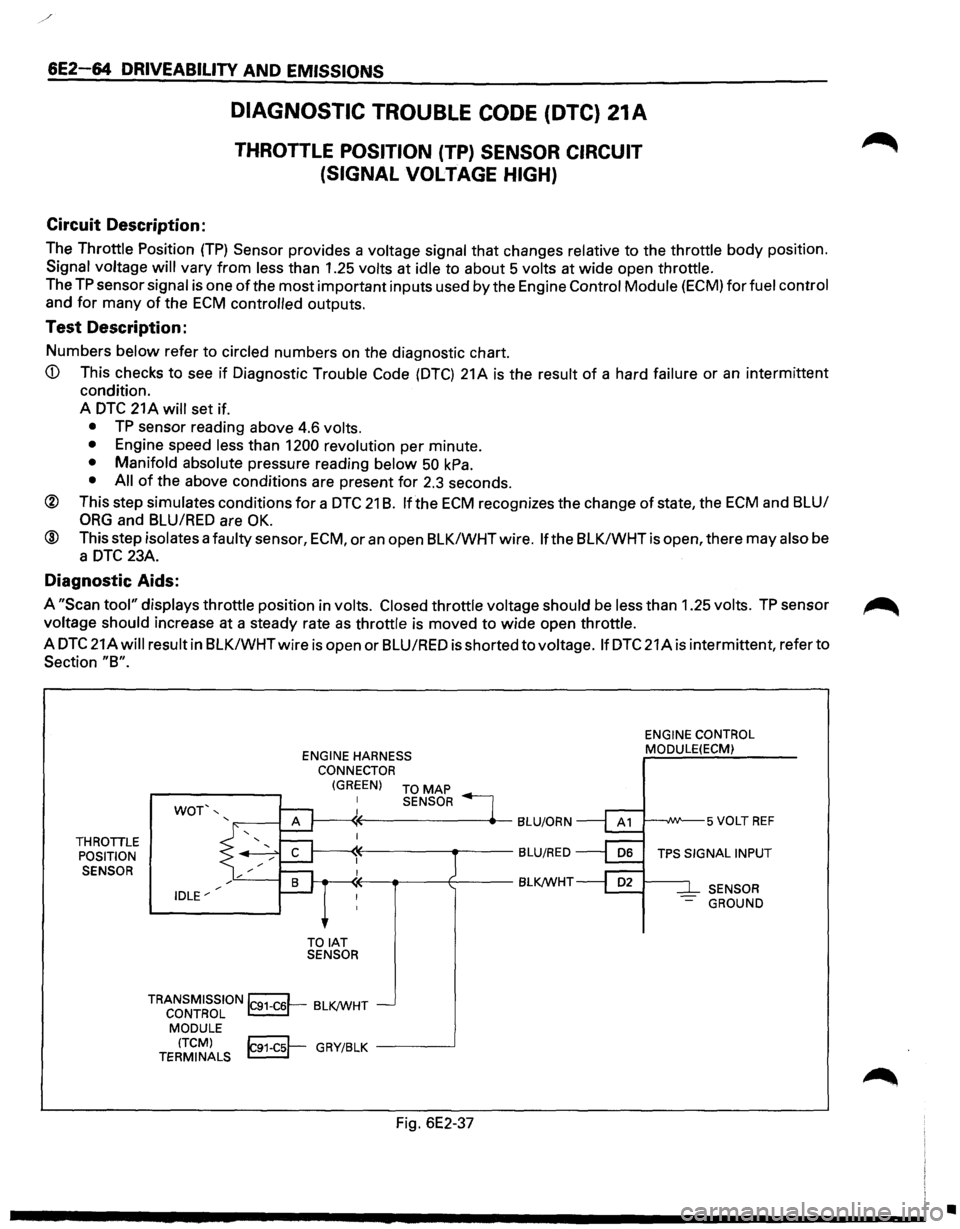
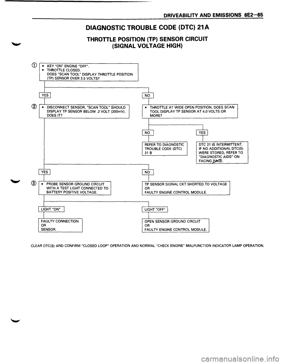
Numbers below refer to circled numbers on the diagnostic chart.
A
DTC 21 A will set if.
• TP sensor reading above 4.6 volts.
• Engine speed less than 1200 revolution per minute.
• Manifold absolute pressure reading below 50 kPa.
• All of the above conditions are present for 2.3 seconds.
® This step simulates conditions for a DTC 21 B. If the ECM recognizes the change of state, the ECM and BLU/
ORG and BLU/RED are OK.
® This step isolates a faulty sensor, ECM, or an open BLK/WHTwire. If the BLK/WHTis open, there may also be
a
DTC 23A.
Diagnostic Aids:
A "Scan tool" displays throttle position in volts. Closed throttle voltage should be less than 1.25 volts. TP sensor ~
voltage should increase at a steady rate as throttle is moved to wide open throttle.
A
DTC 21Awill result in BLK/WHTwire is open or BLU/RED is shorted to voltage. If DTC 21A is intermittent, refer to
Section "8".
THROTILE
POSITION
SENSOR
WOT',
IDLE"' ENGINE
HARNESS
CONNECTOR
(GREEN) TO MAP
TOIAT SENSOR SENSOR
TRANSMISSION~ BLK/WHT CONTROL ~-
MODULE
(TCM)
~ GRY/BLK -----.J TERMINALS ~
Fig. 6E2-37
ENGINE CONTROL
MODULE(ECM)
SENSOR
-GROUND
•
Page 761 of 1928
®
DRIVEABILITY AND EMISSIONS 6E2-65
DIAGNOSTIC TROUBLE CODE (DTC) 21A
THROTILE POSITION (TP) SENSOR CIRCUIT
(SIGNAL
VOLTAGE HIGH)
• KEY "ON" ENGINE "OFF". • THROTTLE CLOSED.
DOES "SCAN TOOL" DISPLAY THROTTLE POSITION
(TP) SENSOR OVER 2.5 VOLTS?
$ $
• DISCONNECT SENSOR, "SCAN TOOL" SHOULD • THROTTLE AT WIDE OPEN POSITION. DOES SCAN
DISPLAY TP SENSOR BELOW .2 VOLT (200mV}. TOOL DISPLAY TP SENSOR AT 4.0 VOLTS OR
DOES IT? MORE?
I
$ cvr
REFER TO DIAGNOSTIC DTC 21 IS
INTERMITTENT.
TROUBLE CODE (DTC} IF NO ADDITIONAL DTC(S} 21 B WERE STORED, REFER TO
"DIAGNOSTIC AIDS" ON FACING~.
~ $
• PROBE SENSOR GROUND CIRCUIT TP SENSOR SIGNAL CKT SHORTED TO VOLTAGE
WITH A TEST LIGHT CONNECTED TO OR BATTERY POSITIVE VOLTAGE. FAULTY ENGINE CONTROL MODULE.
I LIGHT "ON" I LIGHT "OFF" I
I FAULTY CONNECTION
OPEN SENSOR GROUND CIRCUIT OR
OR SENSOR. FAULTY ENGINE CONTROL MODULE.
CLEAR DTC(S}
AND CONFIRM "CLOSED LOOP" OPERATION AND NORMAL "CHECK ENGINE" MALFUNCTION INDICATOR LAMP OPERATION.