engine overheat ISUZU TROOPER 1995 Workshop Manual
[x] Cancel search | Manufacturer: ISUZU, Model Year: 1995, Model line: TROOPER, Model: ISUZU TROOPER 1995Pages: 1928
Page 21 of 1928
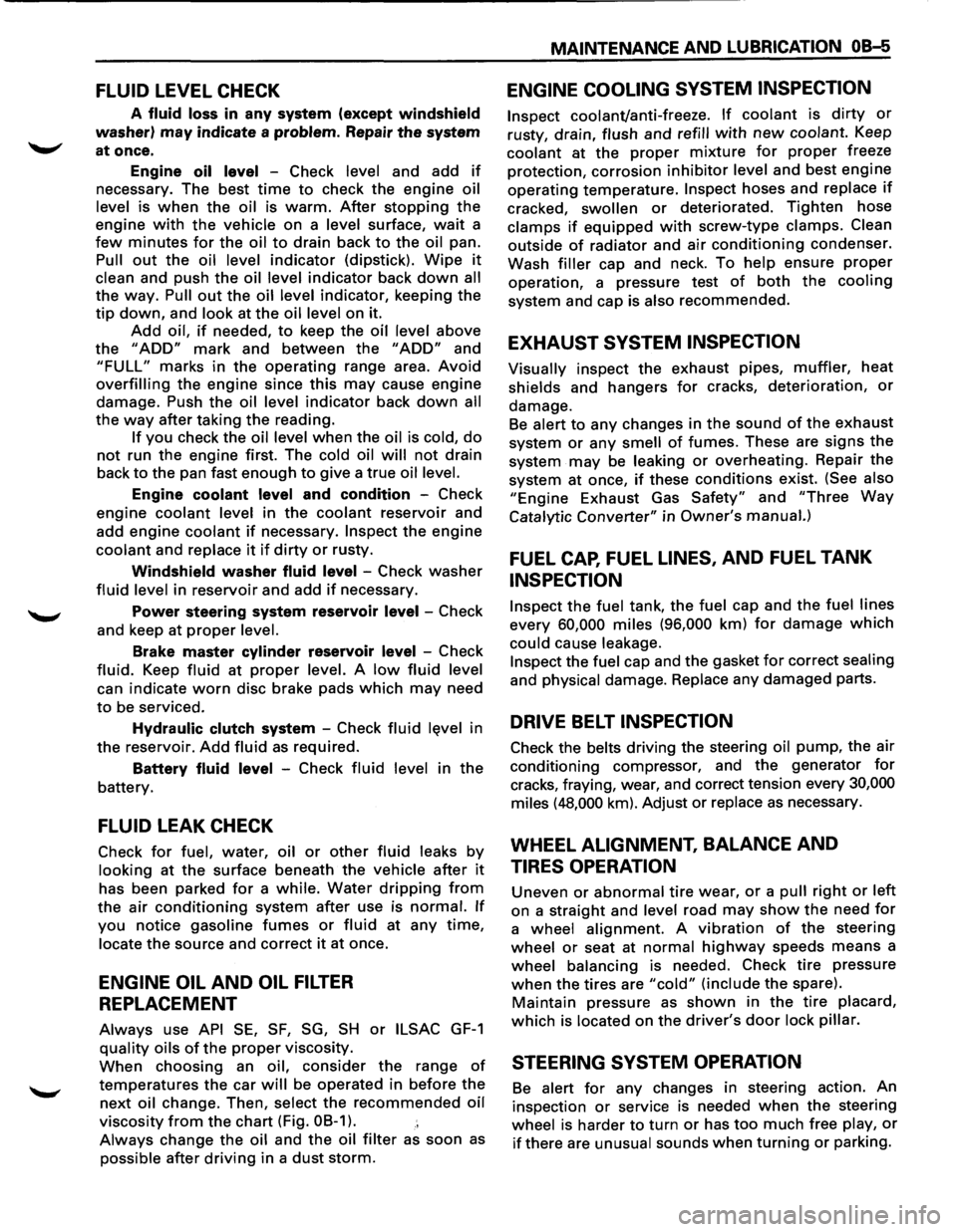
FLUID LEVEL CHECK
A fluid loss in any system (except windshield
washer) may indicate a problem. Repair the system
at once.
Engine
oil level -Check level and add if
necessary. The best time to check the engine oil
level is
when the oil is warm. After stopping the
engine with the vehicle on a level surface, wait a
few minutes for the oil to drain back to the oil pan.
Pull
out the oil level indicator (dipstick). Wipe it
clean and push the oil level indicator back down all
the
way. Pull out the oil level indicator, keeping the
tip down, and look at the oil level on it.
Add oil, if needed, to keep the oil level above
the
"ADD" mark and between the "ADD" and
"FULL" marks in the operating range area. Avoid
overfilling the engine since this may cause engine
damage. Push
the oil level indicator back down all
the
way after taking the reading.
If you check the oil level when the oil is cold, do
not run the engine first. The cold oil will not drain
back
to the pan fast enough to give a true oil level.
Engine coolant level and condition -Check
engine coolant level in the coolant reservoir and
add engine
coolant if necessary. Inspect the engine
coolant and replace it if dirty or rusty.
Windshield washer fluid level -Check washer
fluid level in reservoir and add if necessary.
Power steering system reservoir level-Check
and keep at
proper level.
Brake master cylinder reservoir level -Check
fluid. Keep fluid at proper level. A low fluid level
can indicate
worn disc brake pads which may need
to be serviced.
Hydraulic clutch system -Check fluid l~vel in
the reservoir.
Add fluid as required.
Battery fluid level -Check fluid level in the
battery.
FLUID LEAK CHECK
Check for fuel, water, oil or other fluid leaks by
looking at the surface beneath the vehicle after it
has been parked for a while. Water dripping from
the air conditioning system after use is normal. If
you notice gasoline fumes or fluid at any time,
locate the source and correct it at once.
ENGINE OIL AND OIL FILTER
REPLACEMENT
Always use API SE, SF, SG, SH or ILSAC GF-1
quality oils of the proper viscosity.
When choosing an oil, consider the range of
temperatures the car will be operated in before the
next oil change. Then, select the recommended oil
viscosity
from the chart (Fig. OB-1).
Always change the oil and the oil filter as soon as
possible after driving in a dust storm.
MAINTENANCE AND LUBRICATION OB-5
ENGINE COOLING SYSTEM INSPECTION
Inspect coolant/anti-freeze. If coolant is dirty or
rusty, drain, flush and refill with new coolant. Keep
coolant at the proper mixture for proper freeze
protection,
corrosion inhibitor level and best engine
operating temperature.
Inspect hoses and replace if
cracked, swollen or deteriorated. Tighten hose
clamps if equipped with screw-type clamps. Clean
outside of radiator and air conditioning condenser.
Wash
filler cap and neck. To help ensure proper
operation, a pressure test of both the cooling
system and cap is also recommended.
EXHAUST SYSTEM INSPECTION
Visually inspect the exhaust pipes, muffler, heat
shields and hangers
for cracks, deterioration, or
damage.
Be alert to any changes in the sound of the exhaust
system
or any smell of fumes. These are signs the
system may be leaking or overheating. Repair the
system at once,
if these conditions exist. (See also
"Engine Exhaust Gas Safety" and "Three Way
Catalytic Converter" in Owner's manual.)
FUEL CAP, FUEL LINES, AND FUEL TANK
INSPECTION
Inspect the fuel tank, the fuel cap and the fuel lines
every
60,000 miles (96,000 km) for damage which
could cause leakage.
Inspect the fuel cap and the gasket for correct sealing
and physical damage. Replace any damaged parts.
DRIVE BELT INSPECTION
Check the belts driving the steering oil pump, the air
conditioning compressor, and the generator
for
cracks, fraying, wear, and correct tension every 30,000
miles (48,000 km). Adjust or replace as necessary.
WHEEL ALIGNMENT, BALANCE AND
TIRES OPERATION
Uneven or abnormal tire wear, or a pull right or left
on a straight and level road may show the need for
a wheel alignment. A vibration of the steering
wheel or seat at normal highway speeds means a
wheel balancing is needed. Check tire pressure
when the tires are "cold" (include the spare).
Maintain pressure as shown in the tire placard,
which is located on the driver's door lock pillar.
STEERING SYSTEM OPERATION
Be alert for any changes in steering action. An
inspection
or service is needed when the steering
wheel is harder
to turn or has too much free play, or
if there are unusual sounds when turning or parking.
Page 507 of 1928
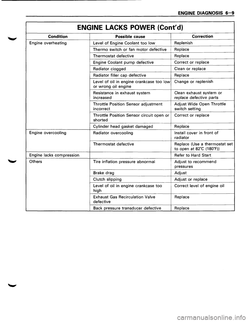
ENGINE DIAGNOSIS 6-9
ENGINE LACKS POWER (Cont'd)
Condition Possible cause Correction
Engine overheating
Level of Engine Coolant too low Replenish
Thermo switch or fan motor defective Replace
Thermostat defective Replace
Engine
Coolant pump defective Correct or replace
Radiator clogged
Clean or replace
Radiator
filler cap defective Replace
Level
of oil in engine crankcase too low Change or replenish
or
wrong oil engine
Resistance in exhaust system
Clean exhaust system or
increased replace
defective parts
Throttle Position Sensor adjustment Adjust
Wide Open Throttle
incorrect switch setting
Throttle Position Sensor circuit open
or Correct or replace
shorted
Cylinder head gasket damaged Replace
Engine overcooling
Radiator
overcooling Install cover
in front of
radiator
Thermostat defective Replace
(Use a thermostat set
to open at a2·c (180.F))
Engine
lacks compression Refer to Hard Start
Others Tire inflation pressure
abnormal Adjust to recommend
pressures
Brake drag Adjust
Clutch slipping Adjust or replace
Level
of oil in engine crankcase too Correct level of engine oil
high
Exhaust Gas
Recirculation Valve Replace
defective
Back pressure transducer defective
Replace
Page 509 of 1928
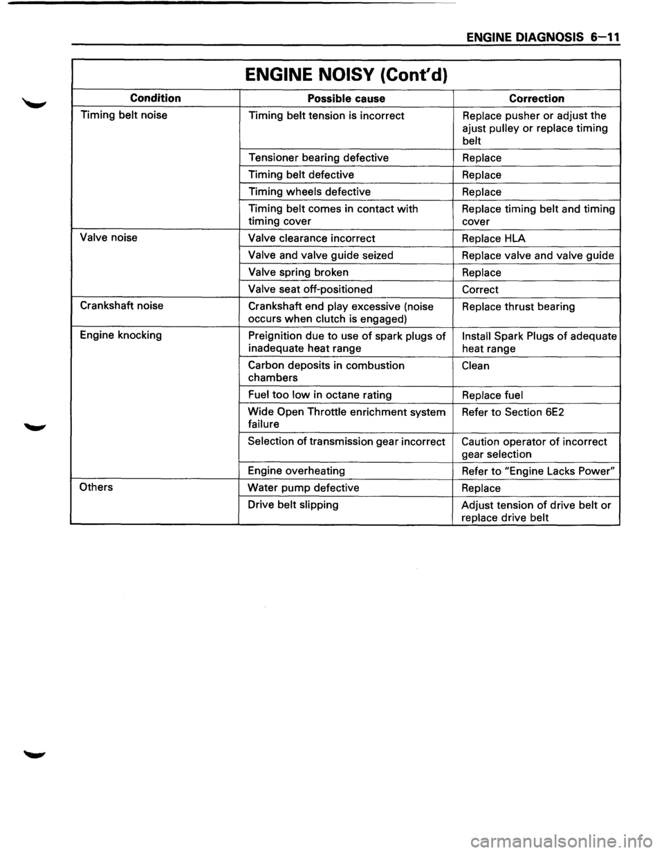
ENGINE DIAGNOSIS 6-11
ENGINE NOISY (Cont'd)
Condition Possible cause Correction
Timing belt noise
Timing belt tension is incorrect Replace pusher or adjust the
ajust
pulley or replace timing
belt
Tensioner bearing defective Replace
Timing belt defective Replace
Timing wheels defective Replace
Timing belt comes in contact with Replace timing belt and timing
timing cover
cover
Valve noise Valve clearance incorrect Replace HLA
Valve and valve guide seized Replace valve and valve guide
Valve spring broken Replace
Valve
seat off-positioned
Correct
Crankshaft noise
Crankshaft end
play excessive (noise Replace thrust bearing
occurs
when clutch is engaged)
Engine knocking
Preignition due
to use of spark plugs of Install Spark Plugs of adequate
inadequate heat range
heat range
Carbon deposits in combustion
Clean
chambers
Fuel too low in octane rating Replace fuel
Wide Open Throttle enrichment system
Refer to Section 6E2
failure
Selection
of transmission gear incorrect Caution operator of incorrect
gear
selection
Engine overheating
Refer to "Engine Lacks Power"
Others Water
pump defective Replace
Drive belt slipping Adjust tension of drive belt or
replace drive belt
Page 631 of 1928
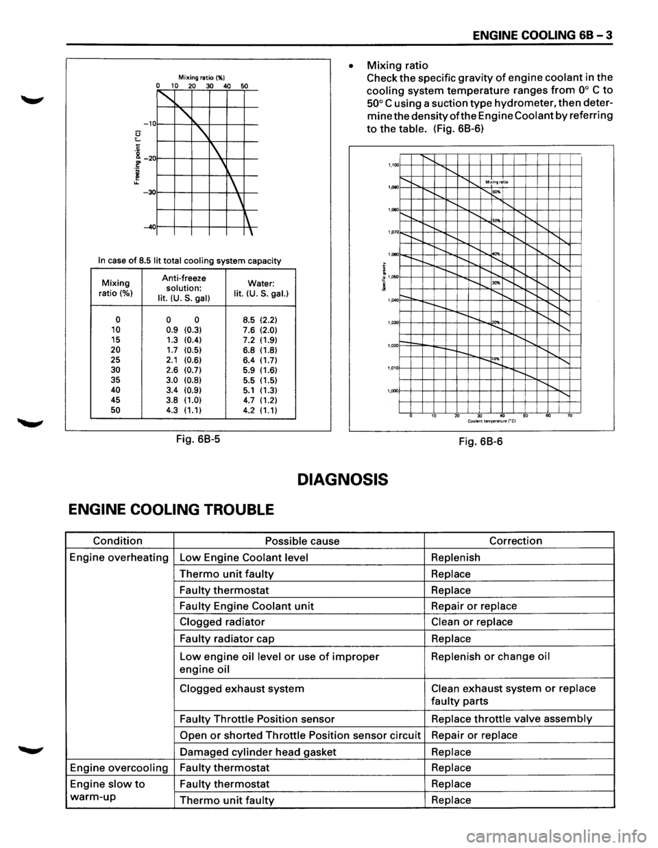
Mixing ratio(%) 0 10 20 30 40 50
~
' -10
'
1
' -30
~ -40
In case of 8.5 lit total cooling system capacity
Mixing Anti-freeze
Water: solution: ratio (%) lit. (U.S. gal) lit. (U.S. gal.)
0 0 0
8.5 (2.2) 10 0.9 (0.3) 7.6 (2.0) 15
1.3 (0.4) 7.2 (1.9) 20 1.7 (0.5) 6.8 (1.8)
25 2.1 (0.6) 6.4 (1.7) 30 2.6 (0.7) 5.9 (1.6)
35 3.0 (0.8) 5.5
(1.5) 40 3.4 (0.9) 5.1 (1.3)
45 3.8 (1.0) 4.7 (1.2) 50 4.3 (1.1)
4.2 (1.1)
Fig. 68-5
ENGINE COOLING 68-3
• Mixing ratio
Check
the specific gravity of engine coolant in the
cooling system temperature ranges from oo C to
50° C using a suction type hydrometer, then deter
mine the densityofthe Engine Coolant by referring
to the table. (Fig. 68-6)
1,100 1'-........ ........ ...... .............. Mixing ratio
~"""--r-... 1'-""' 1,1)90
........ ...... ........ ........ .......... '
1,000
'"" 1,07 o......_ 1'-........ I'-.......... I"-........ .......
I"-........ ..........
................. I"-........
'
1,080
....... I"-........ ~ ........ ......
........ "'" ~"""--r--..... 1,050
r-. ........ ~ .......... ......
---
........ ........ 1,040
r-.... !'--.. 1'-0 '"" ~"""--1'-.... ........ 1,03
1--....... ........ r--~ ........
'
1,020
....... ~ 1'-0 ~"""---.... 1,01
...... ,
'
1,000
10 20 30 40 50 60 70 Coolant temperature ("C)
Fig. 68-6
DIAGNOSIS
ENGINE COOLING TROUBLE
Condition Possible cause Correction
Engine
overheating Low Engine Coolant level Replenish
Thermo unit faulty Replace
Faulty
thermostat Replace
Faulty
Engine Coolant unit Repair or replace
Clogged
radiator Clean or replace
Faulty
radiator cap Replace
Low engine oil level or use of improper Replenish or change oil
engine oil
Clogged exhaust system Clean exhaust system or replace
faulty parts
Faulty Throttle Position sensor Replace throttle valve assembly
Open or shorted Throttle Position sensor circuit Repair or replace
Damaged cylinder head gasket Replace
Engine overcooling Faulty thermostat Replace
Engine slow to Faulty thermostat Replace
warm-up Thermo unit faulty Replace
Page 636 of 1928
'.,~-' r.
68-8 ENGINE COOLING
2. Radiator hose
• Disconnect inlet hose and outlet hose from the
engine.
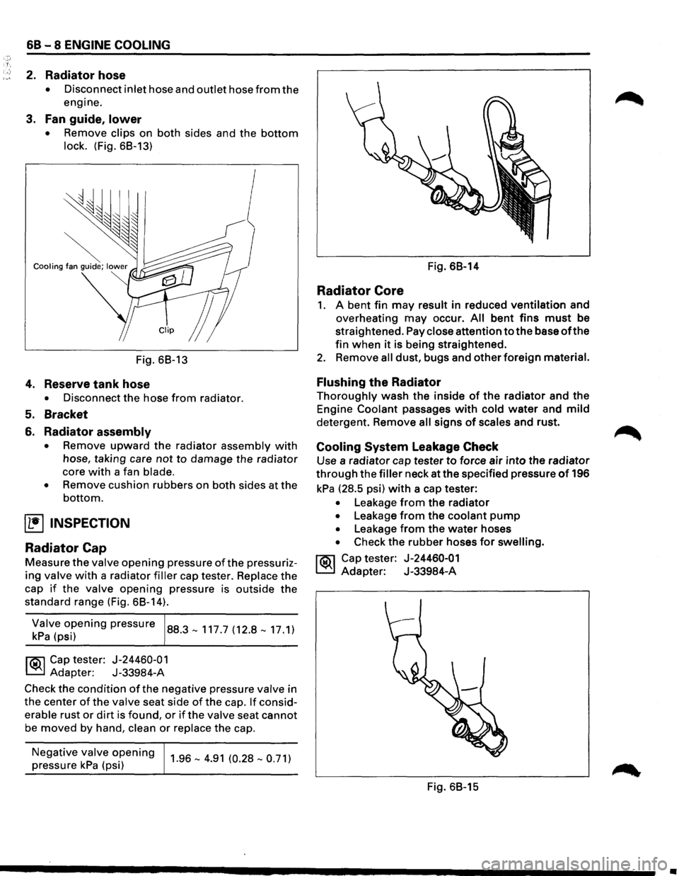
3. Fan guide, lower
• Remove clips on both sides and the bottom
lock. (Fig. 68-13)
~ Cooling fan guide; lower
~
Clip
Fig. 68-13
4. Reserve tank hose
• Disconnect the hose from radiator.
5. Bracket
6. Radiator assembly
• Remove upward the radiator assembly with
hose, taking care not to damage the radiator
core
with a fan blade.
• Remove cushion rubbers on both sides at the
bottom.
~ INSPECTION
Radiator Cap
Measure the valve opening pressure of the pressuriz
ing valve with a radiator filler cap tester. Replace the
cap
if the valve opening pressure is outside the
standard range (Fig. 68-14).
~;!v(~~i~ening pressure 88.3-117.7 (12.8-17.1)
l'i':'il Cap tester: J-24460-01
~ Adapter: J-33984-A
Check the
condition of the negative pressure valve in
the center
of the valve seat side of the cap. If consid
erable rust
or dirt is found, or if the valve seat cannot
be
moved by hand, clean or replace the cap.
Negative
valve opening
pressure kPa (psi) 1.96-4.91 (0.28-0.71)
Fig. 68-14
Radiator Core
1. A bent fin may result in reduced ventilation and
overheating
may occur. All bent fins must be
straightened. Pay
close attention to the base of the
fin when it is being straightened.
2. Remove all dust, bugs and other foreign material.
Flushing the Radiator
Thoroughly wash the inside of the radiator and the
Engine
Coolant passages with cold water and mild
detergent. Remove all signs of scales and rust.
Cooling System Leakage Check
Use a radiator cap tester to force air into the radiator
through the filler neck at the specified pressure of 196
kPa (28.5 psi) with a cap tester:
• Leakage from the radiator
• Leakage from the coolant pump
• Leakage from the water hoses
• Check the rubber hoses for swelling.
rt:\1 Cap tester: J-24460-01
~ Adapter: J-33984-A
Fig. 68-15
•
Page 788 of 1928
6E2-92 DRIVEABILITY AND EMISSIONS
LACK OF POWER, SLUGGISH OR SPONGY
Definition: Engine delivers less than expected power.
Little or no increase in speed when
accelerator
pedal is pushed down part
way.
PRELIMINARY CHECKS
• Perform the careful visual/physical checks as
described at start of "Symptoms," Section "6E2-
B."
•
Compare customer's car to similar unit. Make sure
the
vehicle has an actual problem.
• Remove air filter and check air filter for dirt, or for
being plugged. Replace as necessary.
FUEL SYSTEM
• CHECK: Rescricted fuel filter.
• CHECK: Fuel pressure, use CHART A-7.
• CHECK: Contaminated fuel.
• CHECK: Fuel injectors are correct for the vehicle.
IGNITION SYSTEM
• CHECK: Ignition timing, using "Scan tool".
• CHECK: Knock sensor system for excessive spark
retard activity. Refer to CHART
C-5. Use
"Scan tool".
• CHECK: Secondary voltage using an oscilloscope
or a spark tester J 26792 (ST-125), or
equivalent, to check for a weak coil.
ADDITIONAL CHECKS
• CHECK: Engine control module grounds for being
clean,
tight and in their proper locations.
See engine control module wiring
diagrams.
• CHECK: Exhaust gas recirculation operation for
being open or partly open all the time.
- Refer to CHART
C-7.
• CHECK: Generator output voltage. Repair if less
than 9
or more than 16 volts.
• CHECK: Exhaust system for possible restriction.
Refer
to CHART B-1.
-Inspect exhaust system for damaged
or collapsed pipes.
-
Inspect muffler for heat damage or
possible internal failure.
• CHECK: Torque converter clutch for proper
operation. Refer
to AUTOMATIC
TRANSMISSION
(SECTION 7A).
ENGINE MECHANICAL
• CHECK: Engine valve timing and compression.
• CHECK: Engine for correct or worn camshaft.
Refer
to ENGINE MECHANICAL
DIAGNOSIS
(SECTION 6A).
DETONATION/SPARK KNOCK
Definition: A mild to severe ping, usually worse under
acceleration. The engine makes sharp
metallic knocks that change with throttle
opening.
Sounds like popcorn popping.
PRELIMINARY CHECKS
• Perform the careful visual/physical checks as
Low engine coolant.
Restricted air
flow to radiator, or restricted
water flow through radiator.
Correct engine
coolant solution should be a 50/
50 mix of anti-freeze engine coolant (or
equivalent) and water.
described at start
of "Symptoms," Section "6E2-FUEL SYSTEM
B."
•
Park/Neutral position switch. Be sure "Scan tool"
indicates drive with gear selector in drive or
overdrive. Use
CHART C-1A.
• If "Scan tool" readings are normal (see facing page
of on-board diagnostic system check) and there
are no engine mechanical faults,
fill fuel tank with a
gasoline
that has a minimum octane reading of 87
and revaluate vehicle performance.
• CHECK: Exhaust gas recirculation system for not
opening. Use CHART C-7.
COOLING SYSTEM
• Check for obvious overheating problems:
• NOTICE: To determine if the condition is caused by
a rich
or lean system, the car should be
driven at the speed
of the complaint.
Monitoring
LT. Fuel Trim will help
identify problem.
Lean-
LT. Fuel Trim above 142. Refer to
"Diagnostic Aids" on facing page of
diagnostic trouble code 44.
Rich-LT. Fuel Trim below 118. Refer to
"Diagnostic Aids" on facing page of
diagnostic trouble code 45.
• CHECK: Fuel pressure, use CHART A-7.
..
Page 858 of 1928
6E2-162 DRIVEABILITY AND EMISSIONS
CHART C-10
AIR CONDITIONING (A/C) SYSTEM FUNCTIONAL CHECK
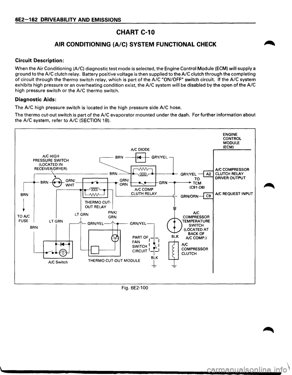
Circuit Description:
When the Air Conditioning (A/C) diagnostic test mode is selected, the Engine Control Module (ECM) will supply a
ground to the
A/C clutch relay. Battery positive voltage is then supplied to the A/C clutch through the completing
of circuit through the thermo switch relay, which is part of the A/C "ON/OFF" switch circuit. If the A/C system
exhibits high pressure or
an overheating condition exist, the A/C system will be disabled by the open of the A/C
high pressure switch or the A/C thermo switch.
Diagnostic Aids:
The A/C high pressure switch is located in the high pressure side A/C hose.
The
thermo cut-out switch is part of the A/C evaporator mounted under the dash. For further information about
the
A/C system, refer to A/C (SECTION 1 8).
BRN
TONC FUSE
NC HIGH
PRESSURE SWITCH
(LOCATED IN
RECEIVER/DRYER)
LTGRN
BRN
NC Switch
NC DIODE
BRN a GRY!YEL
THERMO CUTOUT RELAY
LTGRN PNK/ GRN
NCCOMP CLUTH RELAY
PARTOF1-FAN I SWITCH I I CIRCUIT I __ I
BLK THERMO CUT-OUT MODULE j_
Fig. 6E2-100
ENGINE
CONTROL
MODULE (ECM)
NC COMPRESSOR CLUTCH RELAY DRIVER OUTPUT
NC REQUEST INPUT
Page 863 of 1928
ENGINE EXHAUST (V6 3.2L) 6F-1
SECTION 6F
ENGINE EXHAUST (V6 3.2L)
\fl CAUTION:
VI Exhaust system components must have enough clearance from the upderbody to prevent overheating the
floor pan and damaging the passenger compartment, insulation
and trim materials.
CONTENTS
General Description . . . . . . . . . . . . . . . . . . . . 6F,....1
Hangers ........................... , ... ..-6f-2
Three Way Catalytic Converter ....• ·; ~. 6F-2
Gasket . . . . . . . . . . . . . . . . . . . . . . . . . . . . . 6F-2
On-Vehicle Service ........ , . . . . . . . . . . . 6F-3
Front Exhaust Pipe ... , " ;< . . . . . . . . . . . . 6F-3
Center Exhaust Pipe.. .. : -. . . . . . . . . . . . . . . . 6F-4
.. .r·
Three Way Catalytic Converter . . . . . . . . . 6F-5
Pre Catalytic Converter . . . . . . . . . . . . . . . 6F-6
Exhaust Silencer . . . . . . . . . . . . . . . . . . . . . 6F-7
Rear Exhaust Pipe . . . . . . . . . . . . . . . . . . . . 6F-8
Exhaust Pipe Mounting Rubber . . . . . . . . 6F-9
Main Data and Specifications ........... 6F-10
Torque Specifications ............... 6F-10
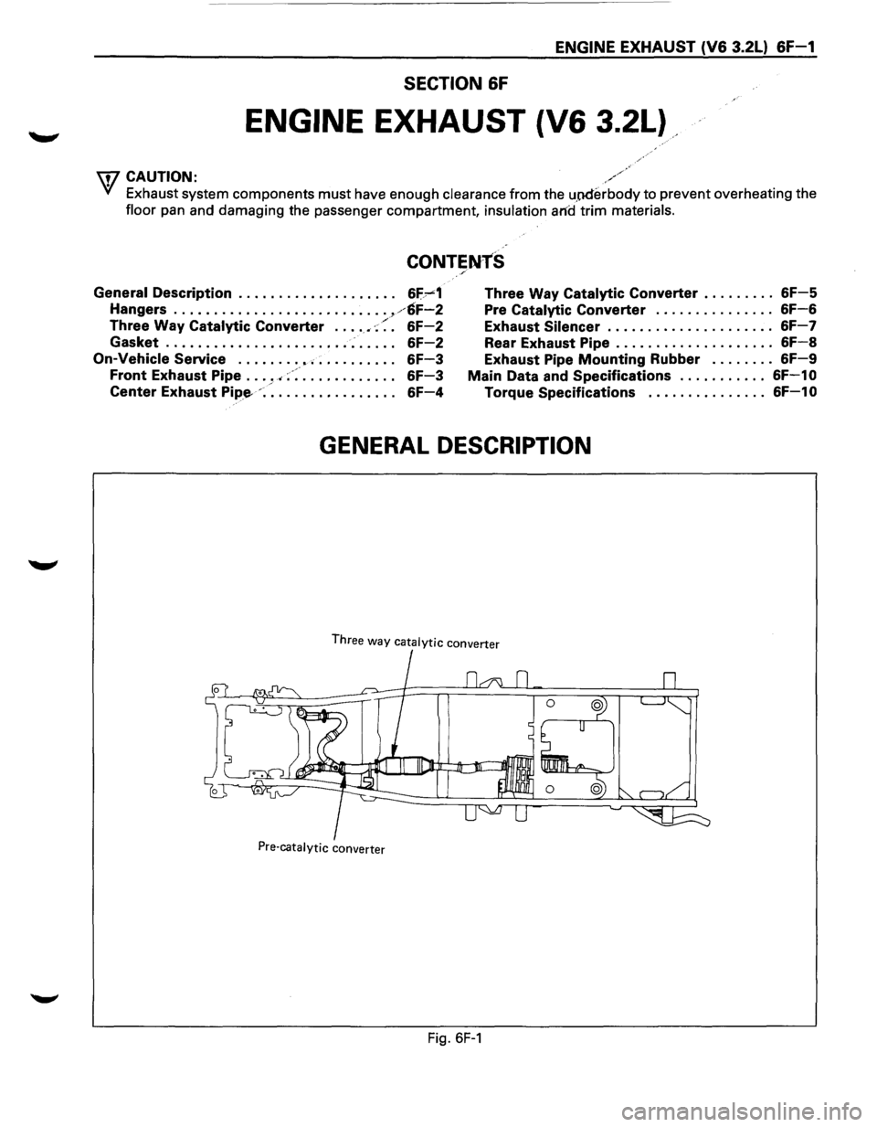
GENERAL DESCRIPTION
Three way catalytic converter
Pre-catalytic converter
Fig. 6F-1