reset ISUZU TROOPER 1995 User Guide
[x] Cancel search | Manufacturer: ISUZU, Model Year: 1995, Model line: TROOPER, Model: ISUZU TROOPER 1995Pages: 1928
Page 769 of 1928
DRIVEABILITY AND EMISSIONS 6E2-73
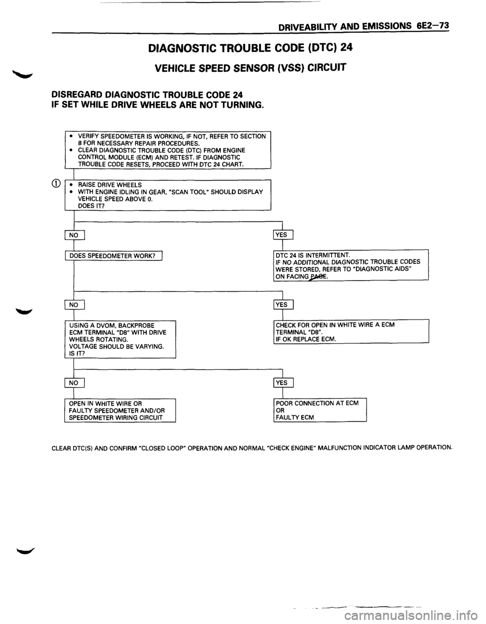
DIAGNOSTIC TROUBLE CODE (DTC) 24
VEHICLE SPEED SENSOR (VSS) CIRCUIT
DISREGARD DIAGNOSTIC TROUBLE CODE 24
IF SET WHILE DRIVE WHEELS ARE NOT TURNING.
• VERIFY SPEEDOMETER IS WORKING, IF NOT, REFER TO SECTION 8 FOR NECESSARY REPAIR PROCEDURES. • CLEAR DIAGNOSTIC TROUBLE CODE (DTC) FROM ENGINE CONTROL MODULE (ECM) AND RETEST. IF DIAGNOSTIC TROUBLE CODE RESETS, PROCEED WITH DTC 24 CHART.
CD • RAISE DRIVE WHEELS • WITH ENGINE IDLING IN GEAR, "SCAN TOOL" SHOULD DISPLAY VEHICLE SPEED ABOVE 0. DOES IT?
$ ~
DOES SPEEDOMETER WORK? I DTC 24 IS INTERMITIENT. IF NO ADDITIONAL DIAGNOSTIC TROUBLE CODES WERE STORED, REFER TO "DIAGNOSTIC AIDS" ON FACING~.
CfJ ~ USING A DVOM, BACKPROBE CHECK FOR OPEN IN WHITE WIRE A ECM
ECM TERMINAL "D8" WITH DRIVE TERMINAL "D8". WHEELS ROTATING. IF OK REPLACE ECM. VOLTAGE SHOULD BE VARYING. IS IT?
$ ~ OPEN IN WHITE WIRE OR POOR CONNECTION AT ECM FAULTY SPEEDOMETER AND/OR OR SPEEDOMETER WIRING CIRCUIT FAULTY ECM
CLEAR DTC(S) AND CONFIRM "CLOSED LOOP" OPERATION AND NORMAL "CHECK ENGINE" MALFUNCTION INDICATOR LAMP OPERATION.
-~---
Page 816 of 1928
6E2 120 DRIVEABILITY AND EMISSIONS
THROTTLE BODY (TB) ASSEMBLY
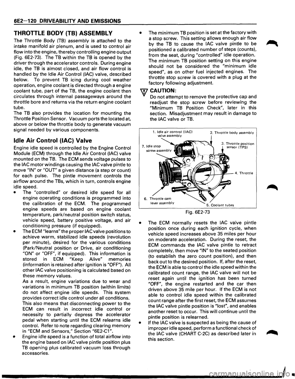
The Throttle Body (TB) assembly is attached to the
intake manifold air
plenum, and is used to control air
flow into the engine, thereby controlling engine output
(Fig. 6E2-73). The TB within the TB is opened by the
driver through the accelerator controls. During engine
idle, the
TB is almost closed, and air flow control is
handled by the Idle Air Control (lAC) valve, described
below. To prevent
TB icing during cool weather
operation, engine
coolant is directed through a engine
coolant tube, part
of the TB, the engine coolant then
circulates through internal passageways around the
throttle bore and returns via the return engine coolant
tube.
The
TB also provides the location for mounting the
Throttle Position
Sensor. Vacuum ports the located at,
above or
below the throttle body to generate vacuum
signal needed
by various components.
Idle Air Control (lAC) Valve
Engine idle speed is controlled by the Engine Control
Module (ECM) through the Idle Air Control (lAC) valve
mounted on the
TB. The ECM sends voltage pulses to
the lAC motor windings causing the lAC valve pintle to
move "IN" or "OUT" a given distance (a step or count)
for each pulse. The pintle movement controls the
airflow around the TBs, which in turn, controls engine
idle speed.
• The "controlled" or desired idle speed for all
engine operating conditions is programmed into
the
calibration of the ECM. The programmed
engine speeds are based on engine coolant
temperature, park/neutral position switch status,
vehicle speed, battery positive voltage, and air
conditioning pressure (if equipped).
• The ECM "learns" the proper lAC valve positions to
achieve warm, stabilized idle speeds (revolution
per minute), desired
for the various conditions
(Park/Neutral position
or Drive, air conditioning
"ON" or "OFF", if equipped). This information is
stored in
ECM "Keep Alive" memories
(information
is retained after ignition is "OFF"). All
other lAC valve positioning is calculated based on
these
memory values.
As a
result, engine variations due to wear and
variations in
minimum TB position (within limits)
do not affect engine idle speeds. This system
provides correct idle control under
all conditions.
This also means
that disconnecting power to the
ECM can result in incorrect idle control or
necessity to partially depress the accelerator
pedal
when starting until the ECM relearns idle
control. Refer to note regarding clearing
memory
in "ECM and Sensors," Section "6E2-C1 ".
•
Engine idle speed is a function of total airflow into
the engine based on
lAC valve pintle position plus
TB opening plus calibrated vacuum loss through
accessories.
• The minimum TB position is set at the factory with
a stop screw. This setting allows enough air flow
by the TB to cause the lAC valve pintle to be
positioned a calibrated
number of steps (counts),
from the seat, during "controlled" idle operation.
The
minimum TB position setting on this engine
should not be considered the
"minimum idle
speed", as on other fuel injected engines. The
throttle stop
screw is covered with a plug at the
factory
following adjustment.
U7 CAUTION:
VI Do not attempt to remove the protective cap and
readjust the stop screw before
reviewi~g t~e
"Minimum TB Position Check", later m th1s
section. Misadjustment may result in damage to
the lAC valve or TB.
Fig. 6E2-73
2. Throttle body assembly
3. Throttle position sensor (TPS)
• The ECM normally resets the lAC valve pintle
position once during each ignition cycle,
when
vehicle speed increases above 35 miles per hour
on moderate acceleration. During the reset, the
ECM commands the lAC valve pintle to retract
completely, then move
"IN" to the seated position
(to establish the zero
count position), and then
back
out to the desired position. If, after the reset,
the
ECM is able to control the idle speed within the
calibrated count range, the
lAC valve will not be
reset again until the ignition has been turned
"OFF", the engine restarted and the car then
driven above 35 mile per hour.
If the ECM is not
able to control idle speed within the calibrated
count range after the first reset, the
ECM assumes
the
lAC valve pintle position is "lost", and enables
another reset
to occur. This will continue until the
pintle position is relearned.
• If the lAC valve is suspected as being the cause of
improper idle speed, perform a functional check of
the lAC valve (CHART C-2C) as described later in
this section.
-----------------------------'
•
Page 823 of 1928
1~1 Measure (If Installing a New Idle Air
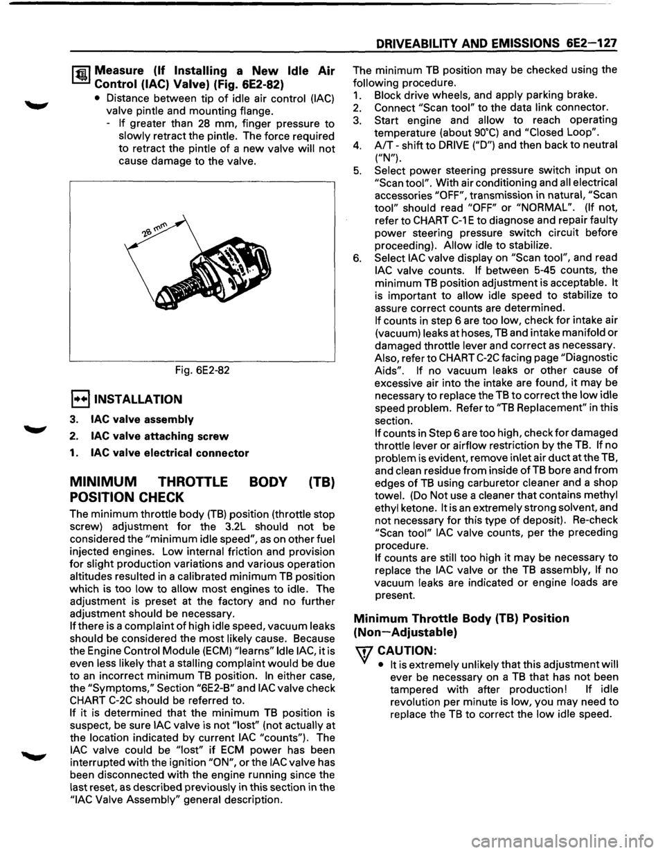
Control (lAC) Valve) (Fig. 6E2-82)
• Distance between tip of idle air control (lAC)
valve pintle and mounting flange.
-
If greater than 28 mm, finger pressure to
slowly retract the pintle. The force required
to retract the pintle
of a new valve will not
cause damage to the valve.
Fig. 6E2-82
E) INSTALLATION
3. lAC valve assembly
2. lAC valve attaching screw
1. lAC valve electrical connector
MINIMUM THROTTLE BODY (TB)
POSITION CHECK
The minimum throttle body (TB) position (throttle stop
screw) adjustment
for the 3.2L should not be
considered the
"minimum idle speed", as on other fuel
injected engines. Low internal friction and provision
for slight production variations and various operation
altitudes resulted in a calibrated
minimum TB position
which is too
low to allow most engines to idle. The
adjustment is preset at the factory and no further
adjustment should be necessary.
If there is a complaint of high idle speed, vacuum leaks
should be considered the
most likely cause. Because
the Engine
Control Module (ECM) "learns" Idle lAC, it is
even less likely
that a stalling complaint would be due
to
an incorrect minimum TB position. In either case,
the
"Symptoms," Section "6E2-B" and lAC valve check
CHART C-2C should be referred to.
If it is determined that the minimum TB position is
suspect,
be sure lAC valve is not "lost'' (not actually at
the location indicated by current
lAC "counts"). The
lAC valve could be "lost" if ECM power has been
interrupted
with the ignition "ON", or the lAC valve has
been disconnected
with the engine running since the
last reset,
as described previously in this section in the
"lAC Valve Assembly" general description.
DRIVEABILITY AND EMISSIONS 6E2-127
The minimum TB position may be checked using the
following procedure.
1. Block drive wheels, and apply parking brake.
2. Connect "Scan tool" to the data link connector.
3. Start engine and allow to reach operating
temperature (about
go•q and "Closed Loop".
4. A/T-shift to DRIVE ("D") and then back to neutral
("N").
5. Select power steering pressure switch input on
"Scan tool". With air conditioning and all electrical
accessories
"OFF", transmission in natural, "Scan
tool" should read "OFF" or "NORMAL". (If not,
refer to
CHART C-1 E to diagnose and repair faulty
power steering pressure switch circuit before
proceeding).
Allow idle to stabilize.
6. Select lAC valve display on "Scan tool", and read
lAC valve counts. If between 5-45 counts, the
minimum
TB position adjustment is acceptable. It
is important to allow idle speed to stabilize to
assure correct counts are determined.
If counts in step 6 are too low, check for intake air
(vacuum) leaks at hoses,
TB and intake manifold or
damaged throttle lever and correct as necessary.
Also, refer to
CHART C-2C facing page "Diagnostic
Aids". If no vacuum leaks or other cause of
excessive air into the intake are found, it may be
necessary
to replace the TB to correct the low idle
speed problem. Refer to
"TB Replacement" in this
section.
If counts in Step 6 are too high, check for damaged
throttle lever or airflow restriction by the
TB. If no
problem is evident, remove inlet air
duct at the TB,
and
clean residue from inside of TB bore and from
edges of TB using carburetor cleaner and a shop
towel. (Do Not use a cleaner that contains methyl
ethyl ketone.
It is an extremely strong solvent, and
not necessary for this type of deposit). Re-check
"Scan tool" lAC valve counts, per the preceding
procedure.
If counts are still too high it may be necessary to
replace the
lAC valve or the TB assembly, If no
vacuum leaks are indicated
or engine loads are
present.
Minimum Throttle Body (TB) Position
(Non-Adjustable)
\fl CAUTION:
VI • It is extremely unlikely that this adjustment will
ever be necessary on a TB that has not been
tampered
with after production! If idle
revolution per minute is low, you may need
to
replace the TB to correct the low idle speed.
Page 917 of 1928
ELECTRONIC DIAGNOSIS
HOW TO DIAGNOSE THE PROBLEM
~ 1. To avoid incorrect diagnostics: this book needs
to be followed accurately. Unless stated: do
not jump
directly to a section that could
contain the solution: some important
information may be missed.
2. The sections in CAPITALS and bold are the
main sections that can be found in the
contents.
3. The GOTO "SECTION" means to continue to
check going to the "section".
4. The GOTHROUGH "SECTION" means to go
through the "section" and then to go back to
the place the GOTHROUGH was written.
5. BASIC ELECTRIC CIRCUITS:
You should understand the basic theory of
electricity. This will include the meaning of
voltage, amps, ohms, and what happens in a
circuit with an open or shorted wire. You
should also be able to read and understand
wiring diagrams.
6. IGNITION CYCLE:
When the car is driven a malfunction can occur
due to a car wiring harness problem, in this
case the driver can reset the system (as on a
personal computer). To reset the computer he
must: (
1) Stop the car and the engine.
(2) Turn the key ignition OFF.
(3) Turn the key ignition ON.
AUTOMATIC TRANSMISSION (4L30·E) 7 A-45
Page 1202 of 1928
8-12 CHASSIS ELECTRICAL
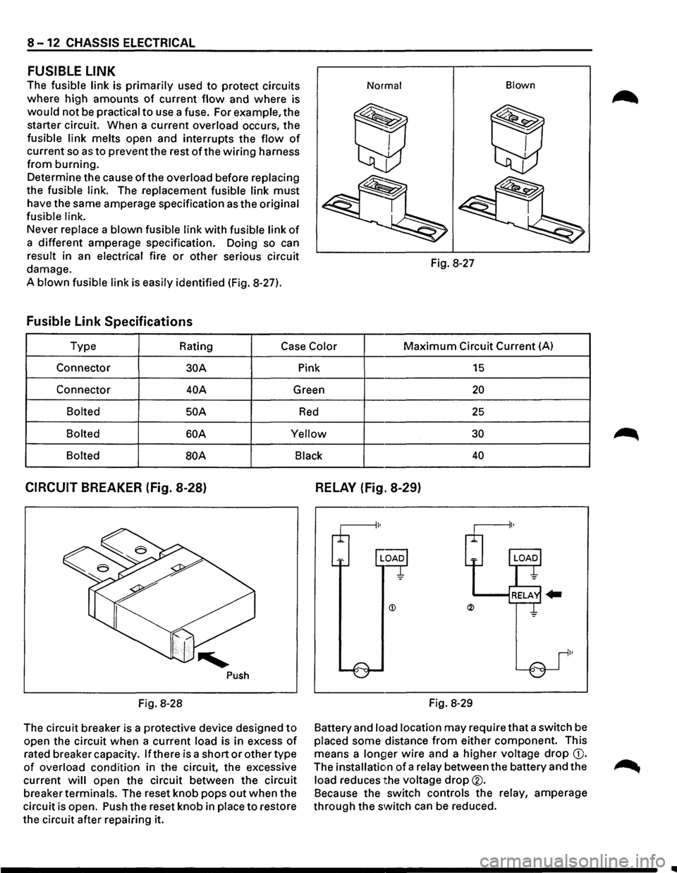
FUSIBLE LINK
The fusible link is primarily used to protect circuits
where high amounts
of current flow and where is
would not be practical to use a fuse. For example, the
starter circuit. When a current
overload occurs, the
fusible link melts open and interrupts the flow of
current so as to prevent the rest of the wiring harness
from burning.
Determine the cause
ofthe overload before replacing
the fusible link. The replacement fusible link must
have the same amperage specification as the original
fusible link.
Never replace a blown fusible link with fusible link of
a different amperage specification. Doing so can
result in an electrical fire or other serious circuit
damage.
A
blown fusible link is easily identified (Fig. 8-27).
Fusible Link Specifications
Normal Blown
Fig.
8-27
Type Rating
Case Color Maximum Circuit Current (A)
Connector
30A Pink 15
Connector 40A Green 20
Bolted 50 A Red 25
Bolted 60A Yellow 30
Bolted
BOA Black 40
CIRCUIT BREAKER (Fig. 8-28)
Push
Fig. 8-28
The circuit breaker is a protective device designed
to
open the circuit when a current load is in excess of
rated breaker capacity. If there is a short or other type
of overload condition in the circuit, the excessive
current
will open the circuit between the circuit
breaker
terminals. The reset knob pops out when the
circuit is open. Push the reset knob in
place to restore
the circuit after repairing it.
RELAY (Fig. 8-29)
Fig. 8-29
Battery and
load location may require that a switch be
placed some distance from either component. This
means a
longer wire and a higher voltage drop G).
The installation of a relay between the battery and the
load reduces the voltage drop®.
Because the switch controls the relay, amperage
through the switch can be reduced.
..
Page 1543 of 1928
CHASSIS ELECTRICAL 8-353
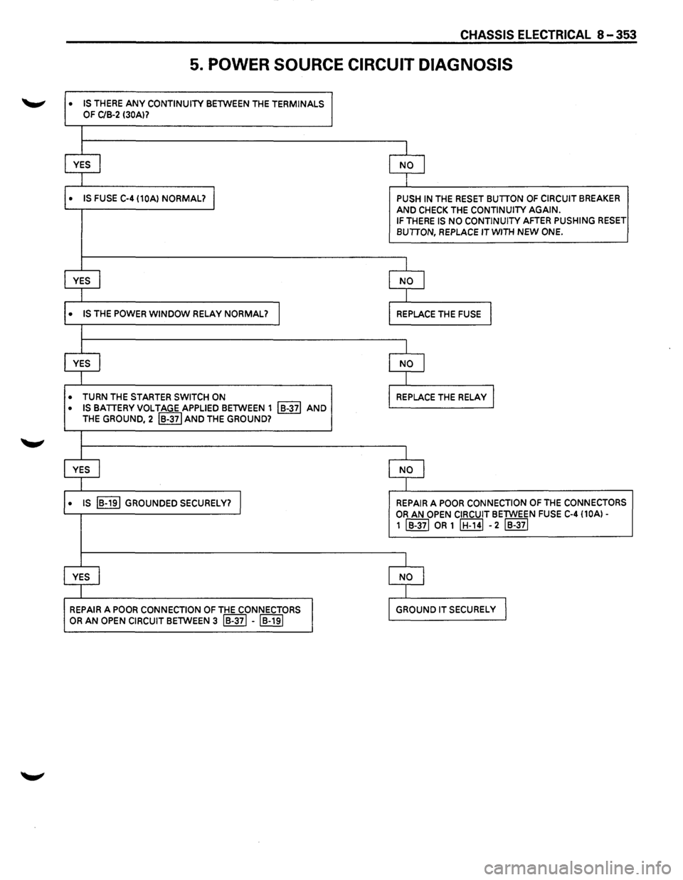
5. POWER SOURCE CIRCUIT DIAGNOSIS
• IS THERE ANY CONTINUITY BETWEEN THE TERMINALS
OF C/B-2 130Al?
I
YES I NO I
I
• IS FUSE C-4 (10Al NORMAL? I PUSH IN THE RESET BUTION OF CIRCUIT BREAKER
AND CHECK THE CONTINUITY AGAIN. IF THERE IS NO CONTINUITY AFTER PUSHING RESET BUTION, REPLACE IT WITH NEW ONE.
I
YES I NO I
I
• IS THE POWER WINDOW RELAY NORMAL? I REPLACE THE FUSE I
I
YES I NO I
I
• TURN THE STARTER SWITCH ON REPLACE THE RELAY I
• IS BATIERY VOLTAGE APPLIED BETWEEN 1 I B-371 AND THE GROUND, 2 IB-371 AND THE GROUND?
1
YES I NO I
I
• IS IB-191 GROUNDED SECURELY? I REPAIR A POOR CONNECTION OF THE CONNECTORS
OR AN OPEN CIRCUIT BETWEEN FUSE C-4 (10A)-
1 IB-371 OR 1 IH-141 -2 IB-371
I
YES I NO I
I
REPAIR A POOR CONNECTION OF THE CONNECTORS GROUND IT SECURELy I
OR AN OPEN CIRCUIT BETWEEN 3 IB-371 -IB-191
Page 1591 of 1928
CRUISE CONTROL 98-7
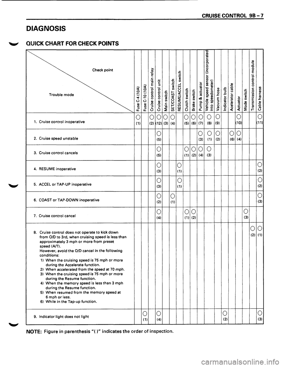
DIAGNOSIS
~ QUICK CHART FOR CHECK POINTS
"0 !!:! 0 0
CD 0 <( ::I ;: w ... Cl) Qi :0 0 <( Cl) 0 0 g Cl) u .r: .r: CD 0. 0 Cl) ::I
CD CD .!!! .!!! c: i==" 0 ""'" E :c 0 ::I 0 Qi :::1 "0 c: :0 en ... 0 '6 Cl) Cl) ::I ::I ·;a ::I
:::1 ... u w w .... ::I CD .,. ·= > .s <( ~ 1-u
0
0 0
0
0 0
0 0
0 0
0 0 1. Cruise control inoperative (
1) (2) (12) (3)
(4) (51 (6) (7) (8) (9) (10) (11)
0 0
0
0 0 0 2. Cruise
speed unstable (5) (3) ( 1) (2) (6) (4)
3. Cruise control cancels 0 0 0
0 0
(51 (
1) (2) (4) (3)
0 0 0 4. RESUME
inoperative (3) ( 1) (2)
0
0 0 5. ACCEL or TAP-UP
inoperative (3) ( 1) (2)
0
0 0 6. COAST or TAP-DOWN
inoperative (2) ( 1) (3)
0 0 0 0 7. Cruise control
cancel (4) ( 1) (2) (3)
0
0 8. Cruise control does not operate to kick down (2) (
1) from 0/D to 3rd, when cruising speed is less than approximately 3 mph or more from preset
speed (A/T). However, avoid the 0/D cancel in the following conditions:
1) When the cruising speed is 75 mph or more
during the
Accelerate function. 21 When accelerated from the speed at 70 mph. 3) When the cruising speed is 75 mph or more
during the Resume function.
4) When the memory speed is less than 3 mph
during the Resume function.
51 When resumed from the memory speed at
6 mph or less. 61 While in the Tap-up function.
9. Indicator light does not light 0 0 0
0 (
1) (4) (2) (3)
NOTE: Figure in parenthesis"()" indicates the order of inspection.
Page 1594 of 1928
98-10 CRUISE CONTROL
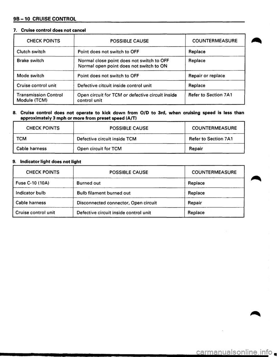
7. Cruise control does not cancel
CHECK POINTS POSSIBLE CAUSE COUNTERMEASURE
Clutch switch Point does not switch to OFF Replace
Brake switch
Normal close point does not switch to OFF Replace
Normal open point does not switch to ON
Mode switch Point does not switch to OFF Repair or replace
Cruise control unit
Defective citcuit inside control unit Replace
Transmission Control Open circuit for TCM or defective circuit inside Refer to Section
7 A 1
Module (TCM) control unit
8. Cruise control does not operate to kick down from 0/D to 3rd, when cruising speed is less than
approximately 3 mph or more from preset speed (A/T)
CHECK POINTS POSSIBLE CAUSE COUNTERMEASURE
TCM Defective circuit inside TCM Refer
to Section 7 A 1
Cable harness Open circuit for TCM
Repair
9. Indicator light does not light
CHECK POINTS POSSIBLE CAUSE COUNTERMEASURE
Fuse
C-10 (10A) Burned out Replace
Indicator
bulb Bulb filament burned out Replace
Cable
harness Disconnected connector, Open circuit Repair
Cruise
control unit Defective circuit inside control unit Replace
..
Page 1724 of 1928
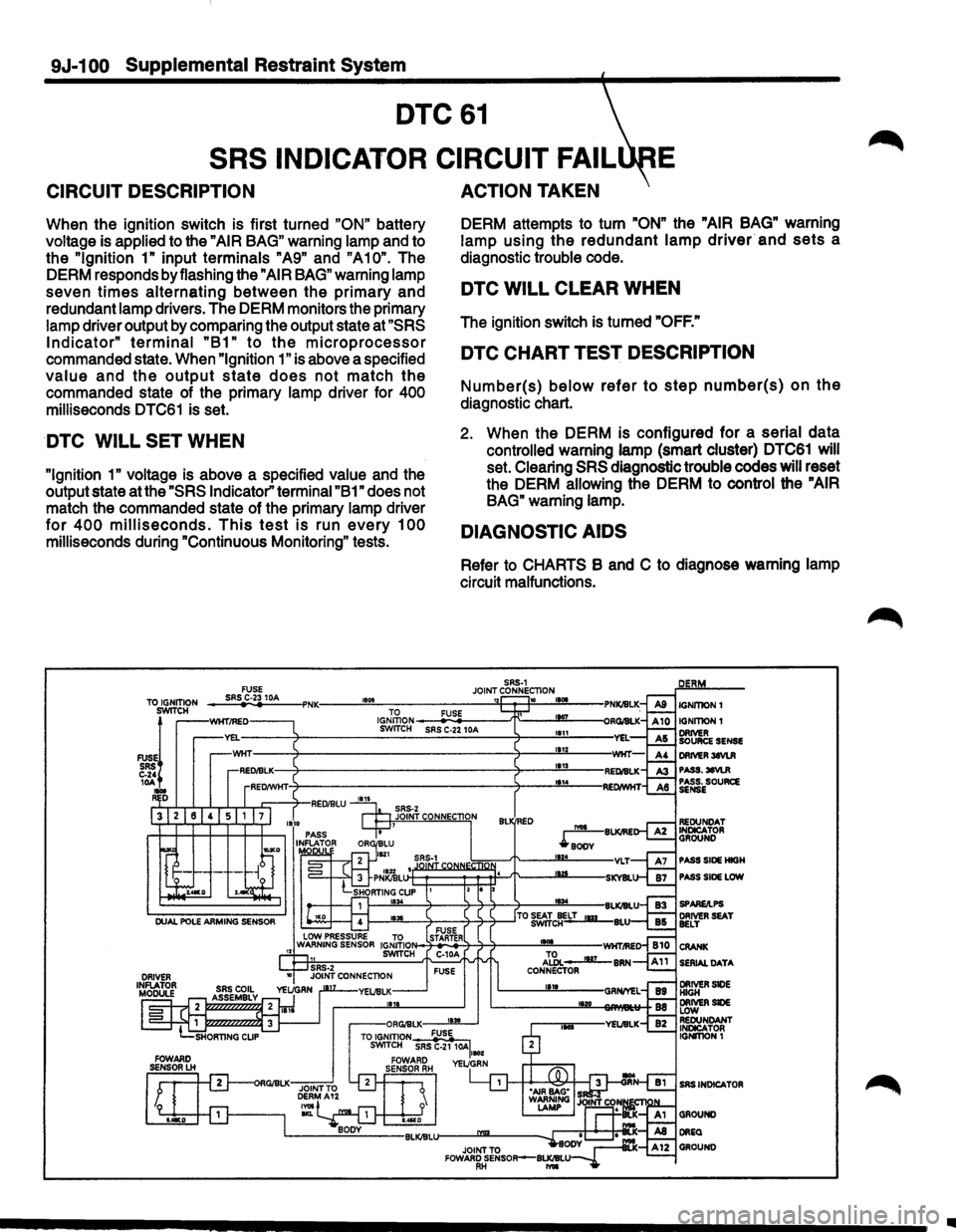
9J-1 00 Supplemental Restraint System
DTC61
SRS
INDICATOR CIRCUIT FAIL E
CIRCUIT DESCRIPTION
When the ignition switch is first turned "ON" battery
voltage is applied to the
"AIR BAG" warning lamp and to
the
"Ignition 1" input terminals "A9" and "A10". The
DERM responds by flashing the
"AIR BAG" warning lamp
seven
times alternating between the primary and
redundant lamp drivers. The DERM monitors the primary
lamp driver output by comparing the output state at
"SRS
Indicator" terminal "B1" to the microprocessor
commanded state. When "Ignition 1" is above a specified
value and the output state does not match the
commanded state of the primary lamp driver for 400
milliseconds DTC61 is set.
DTC WILL SET WHEN
"Ignition 1" voltage is above a specified value and the
output state at the
"SRS Indicator" terminal "B1" does not
match the commanded state of the primary lamp driver
for 400 milliseconds. This test is run every 100
milliseconds during "Continuous Monitoring" tests.
ACTION TAKEN
DERM attempts to turn "ON" the "AIR BAG" warning
lamp using
the redundant lamp driver and sets a
diagnostic trouble code.
DTC WILL CLEAR WHEN
The ignition switch is turned "OFF."
DTC CHART TEST DESCRIPTION
Number(s) below refer to step number(s) on the
diagnostic chart.
2. When the DERM is configured for a serial data
controlled warning lamp (smart cluster) DTC61 will
set. Clearing
SRS diagnostic trouble codes will reset
the DERM allowing the DERM to control the
"AIR
BAG"
warning lamp.
DIAGNOSTIC AIDS
Refer to CHARTS B and C to diagnose warning lamp
circuit malfunctions.
Ill