tailgate ISUZU TROOPER 1995 Workshop Manual
[x] Cancel search | Manufacturer: ISUZU, Model Year: 1995, Model line: TROOPER, Model: ISUZU TROOPER 1995Pages: 1928
Page 1192 of 1928
-·*; ~---
8-2 CHASSIS ELECTRICAL
GENERAL INFORMATION
The chassis electrical system is of 12-volt specifications with a negative ground polarity.
Wire sizes are appropriate
to respective circuits, and classified by color. (The classification of harnesses by
color is shown on the circuit diagram for ease of harness identification.)
The
wire size is determined by load capacity and the length of wire required.
The
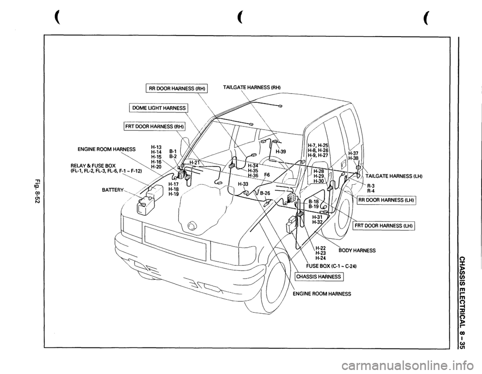
vehicle harnesses are: body harness, chassis harness, engine room harness, instrument harness,
transmission harness, engine
ECGI harness, dome light harness, door harness, rear body harness, tailgate
harness,
SRS harness and battery cables.
The harnesses are protected either
by tape or corrugated tube, depending on harness location.
The circuit
for each system consists of the power source, wire, fuse, relay, switch, load parts and ground, all of
which are shown on the circuit diagram.
In this manual, each electrical device is classified by system. For major parts shown on the circuit based on
the circuit diagram
for each system, a summary, diagnosis oftroubles, inspection and removal and installation
procedures are detailed.
NOTES FOR WORKING ON ELECTRICAL ITEMS
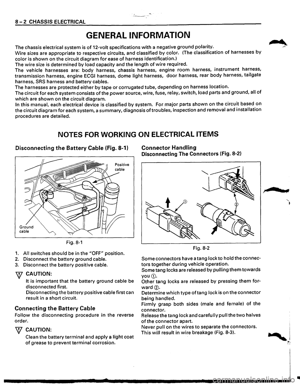
Disconnecting the Battery Cable (Fig. 8-1)
Ground cable
Fig. 8-1
1. All switches should be in the "OFF" position.
2. Disconnect the battery ground cable.
3. Disconnect the battery positive cable.
W CAUTION:
It is important that the battery ground cable be
disconnected first.
Disconnecting the battery positive cable first can
result in a short circuit.
Connecting the Battery Cable
Follow the disconnecting procedure in the reverse
order.
\V CAUTION:
Clean the battery terminal and apply a light coat
of grease to prevent terminal corrosion.
Connector Handling
Disconnecting The Connectors (Fig. 8-2)
Fig. 8-2
Some connectors have a tang lock to hold the connec
tors together during vehicle operation.
Some tang locks are released by pulling them towards
you
G).
Other tang locks are released by pressing them for
ward®.
Determine which type oftang lock is on the connector
being handled.
Firmly grasp both sides (male and female)
of the
connector. Release the tang lock and carefully pull the
two halves
of the connector apart.
Never pull on the wires
to separate the connectors.
This
will result in wire breakage (Fig. 8-3).
.,
..
Page 1220 of 1928
8-30 CHASSIS ELECTRICAL
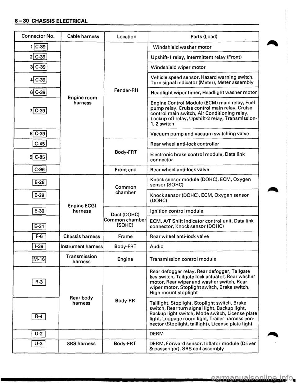
Connector No.
Cable harness
Location Parts (load)
1jC-39I Windshield washer motor
21 C-391 Upshift-1 relay, Intermittent relay (Front)
31 C-391 Windshield wiper motor
41 C-39j Vehicle speed
sensor, Hazard warning switch,
Turn
signal indicator (Meter), Meter assembly
sl C-391 Fender-RH Headlight wiper timer, Headlight washer motor
Engine room
harness Engine Control Module (ECM)
main relay, Fuel
71 C-391 pump relay, Cruise control main relay, Cruise
control main switch, Air Conditioning relay,
Lockup off relay, Upshift-2 relay, Transmission-
1, 2 switch
al C-391 Vacuum pump and vacuum switching valve
I C-451 Rear wheel anti-lock controller
sl c-asl
Body-FRT Electronic brake control module, Data link
connector
I C-961 Front end Rear wheel
anti-lock valve
I E-281 Knock sEmsor module (DOHC), ECM, Oxygen
Common sensor (SOHC)
I E-291 chamber Knock sensor (DOHC), ECM, Oxygen sensor
(DOHC)
Engine
ECGI
I E-30 I harness Duct (DOHC) Ignition control
module
Common chamber
ECM, AfT Shift indicator control unit, Data link
I
E-311 (SOHC) connector, Knock sensor (DOHC)
~ Chassis harness Frame
Rear wheel anti-lock valve
11-391 Instrument
harness
Body-FRT Audio
IM-161 Transmission
Engine Transmission control module harness
Rear defogger
relay, Rear defogger, Tailgate
~
key switch, Tailgate lock actuator, Rear washer
motor, A:ear wiper and washer switch, Rear
wiper motor, Stoplight switch, Brake switch,
High
mount stoplight
Rear body Body-RR
harness Taillight, Stoplight, Stoplight switch, Brake
switch,
near turn signal light, Backup light,
~
Backup light switch, Mode switch, License plate
light, Lu!;)gage room light, Trailer harness con-
nector
(Stoplight, taillight), License plate light
~ DERM
00 SRS harness Body-FRT
DERM, Forward sensor, Inflator module (Driver
& passenger),
SRS coil assembly
•
Page 1225 of 1928
::!! cc 00 I U1 N
(
I RR
DOOR
HARNESS
(RH)
I
I DOMEUGHTHARNESSJ
.--------------
I FRT
DOOR
HARNESS
(RH)
I
ENGINE
ROOM
HAR~NESS
~:~i 16
RELAY
& FUSE
BOX
20
(FL-1,
FL-2,
FL-3,
FL-6,
F ) -------------"-
~/ /
BATTERY"------,//
"
\_
(
TAILGATE
HARNESS
(RH)
\,
TAILGATE
HARNESS
(LH)
R-3 R-4
RR
DOOR
HARNESS
ILHl
FRT
DOOR
HARNESS
(LH)
H-22 H-23 H-24
BODY
HARNESS
FUSE
BOX
(C-1
-C-241
ENGINE
ROOM
HARNESS
(
0 :1: )> fJ)
fJ) Ci) m rm 0 -4 ::0 n )> r-eo I w (J1
Page 1318 of 1928
8-128 CHASSIS ELECTRICAL
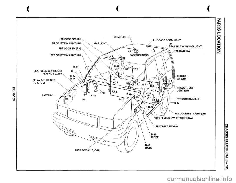
DOME LIGHT, LUGGAGE ROOM LIGHT, COURTESY LIGHT,
MAP LIGHT, SEAT BELT SWITCH AND WARNING BUZZER
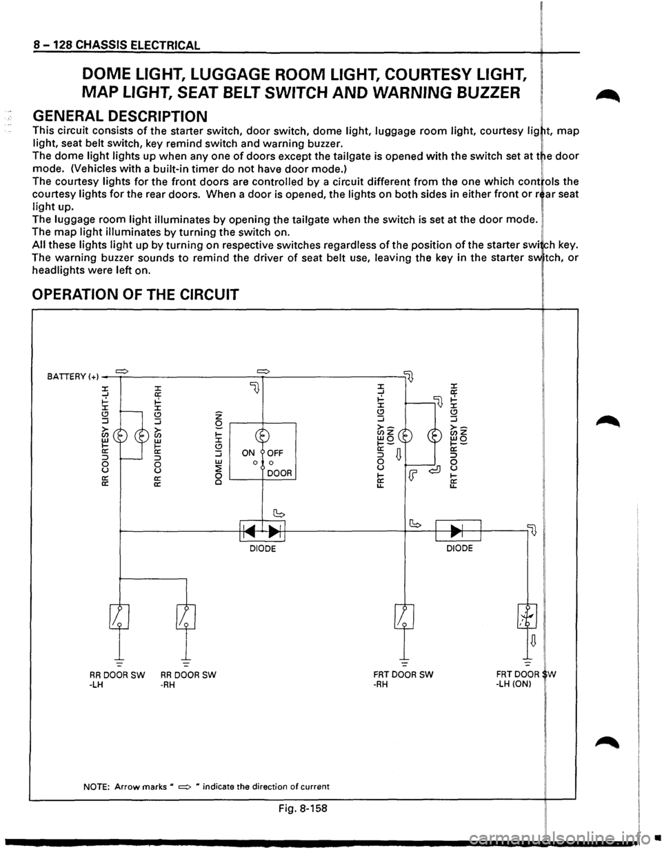
GENERAL DESCRIPTION
This circuit consists of the starter switch, door switch, dome light, luggage room light, courtesy lig t, map
light, seat belt switch, key remind switch and warning buzzer.
The dome
light lights up when any one of doors except the tailgate is opened with the switch set at t e door
mode. (Vehicles with a built-in timer do not have door mode.) !
The courtesy lights for the front doors are controlled by a circuit different from the one which cont ols the
courtesy
lights for the rear doors. When a door is opened, the lights on both sides in either front or r ar seat
light up.
The
luggage room light illuminates by opening the tailgate when the switch is set at the door mode.
The
map light illuminates by turning the switch on.
All these lights light up by turning on respective switches regardless of the position of the starter swi ch key.
The
warning buzzer sounds to remind the driver of seat belt use, leaving the key in the starter sv.. tch, or
headlights were left on.
OPERATION OF THE CIRCUIT
BATIERY (+) _....,.=>..:.__ _________ =>~---------lij
l} :X: :X: ...J a: ~ ~ :X: :X: Q .....__ (.!) ...J :J
~~ ®~ II: li: :::> r----:::> 0 0 u u a: a:
a: a:
z Q r---t----,
~ Go (.!) :J w ON OFF 0 0
~ DOOR 0 '-----+------'
~----------~~~~~~~~lr-l ____________ ,_b __ +-~~~-'--~'---,~ II...... 111"""11 Ill"""' J
-:..._ -=-
RRDOORSW RRDOORSW -LH -RH
DIODE DIODE
-=
FRTDOOR SW -RH
NOTE: Arrow marks u =:> H indicate the direction of current
Fig. 8-158
FRTDOOR W -LH (ON)
•
Page 1319 of 1928
, ce· co I .... U1 co
(
RR
DOOR
SW
(RH)
, '-..__
RR
COURTESY LIGHT
(RH)
, ,
~
MAP
LIGHT~
FRT
DOOR
SW
(RH)
,
~,
~
,·
"·,.
FRT
COURTESY LIGHT (RH),
\\,
:~~ /,
' ;. >,I
H-21
(\
/~~
\,
SEAT
BELT,
KEY
&LIGHT
B-1,
REMIND BUZZER
~
""
~
H-12,""
RELAY & FUSE
BOX,
~
14
',,
(FL-1, FL-2)
'~
'
BATIERY
FUSE
BOX IC-10, C-16)
( DOME
LIGHT
/ 1 LUGGAGE
ROOM
LIGHT
1-9 SEATBELTWARNING
LIGHT
, TAILGATE
SW
/
RR
DOOR
SW(LH)
I(Y.£!
= /
I RR
COURTESY
LIGHT(LH)
~11
) I
FRT
DOOR
sw.
(LH)
-
I.
B-22
FRT
COURTESY LIGHT
(LH)
KEY
REMIND SW,
(STARTER
SW)
SEAT BELT
SW
(LH)
(
~ :lJ ~ r-0 0 ~ 0 2
0 :c 1:i en 0 m I""' m 0 -t ::0 cs )> I""' co I ...a N CD
Page 1324 of 1928
![ISUZU TROOPER 1995 Workshop Manual 8-134 CHASSIS ELECTRICAL
STARTER SWITCH
Refer to "START AND CHARGING" of this section.
DOOR SWITCH
(1!] INSPECTION
Push o
[]:!]
Connector No. IR-11IIB-22IIB-35l Switch
operation Terminal 1 B](/img/61/57183/w960_57183-1323.png "ISUZU TROOPER 1995 Workshop Manual 8-134 CHASSIS ELECTRICAL
STARTER SWITCH
Refer to \"START AND CHARGING\" of this section.
DOOR SWITCH
(1!] INSPECTION
Push o
[]:!]
Connector No. IR-11IIB-22IIB-35l Switch
operation Terminal 1 B")
8-134 CHASSIS ELECTRICAL
STARTER SWITCH
Refer to "START AND CHARGING" of this section.
DOOR SWITCH
(1!] INSPECTION
Push o
[]:!]
Connector No. IR-11IIB-22IIB-35l Switch
operation Terminal 1 Body
Push
Release
Fig. 8-164
I t!ll Check to see if there is any continuity between
the
terminals and the body while operating the
door switch. (Fig. 8-164)
Repair
or replace the switch, when the result of
inspection is found abnormal.
B REMOVAL (FIG. 8-165)
Preparation: Disconnect the battery ground cable.
1. Door switch
Fig. 8-165
1.
Door switch
• Remove the screw.
• Disconnect the connector of the switch.
B INSTALLATION
To install, follow the removal steps in the averse
order.
TAILGATE SWITCH
(b!] INSPECTION
Release
Fig. 8-166
I til Check to see if there is any continuity b tween
the
terminals and the body while operati g the
tailgate switch. (Fig. 8-166)
Repair
or replace the tailgate switch wh n the
result of inspection is found abnormal.
B REMOVAL (FIG. 8-167)
Preparation: Disconnect the battery ground cable.
Fig. 8-167
1.
Tailgate switch
• Remove the screws.
• Disconnect the connector of the switch.
•
Page 1332 of 1928
8-142 CHASSIS ELECTRICAL
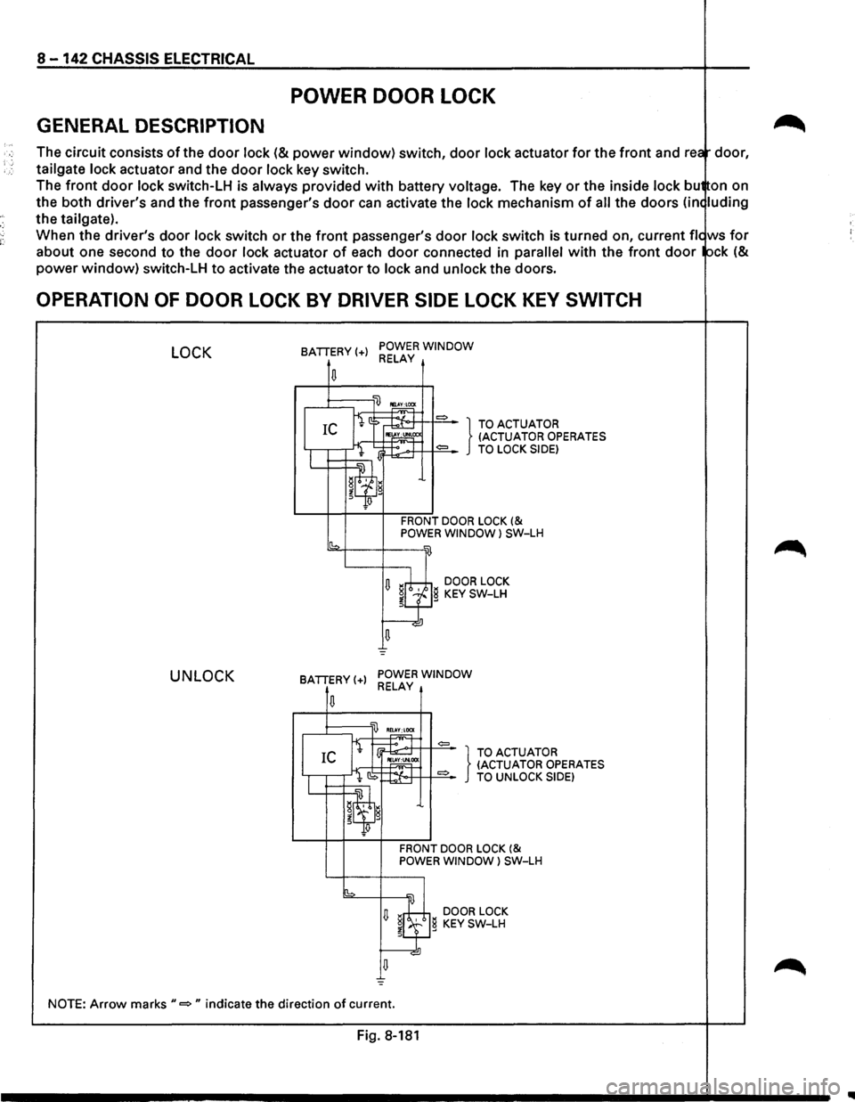
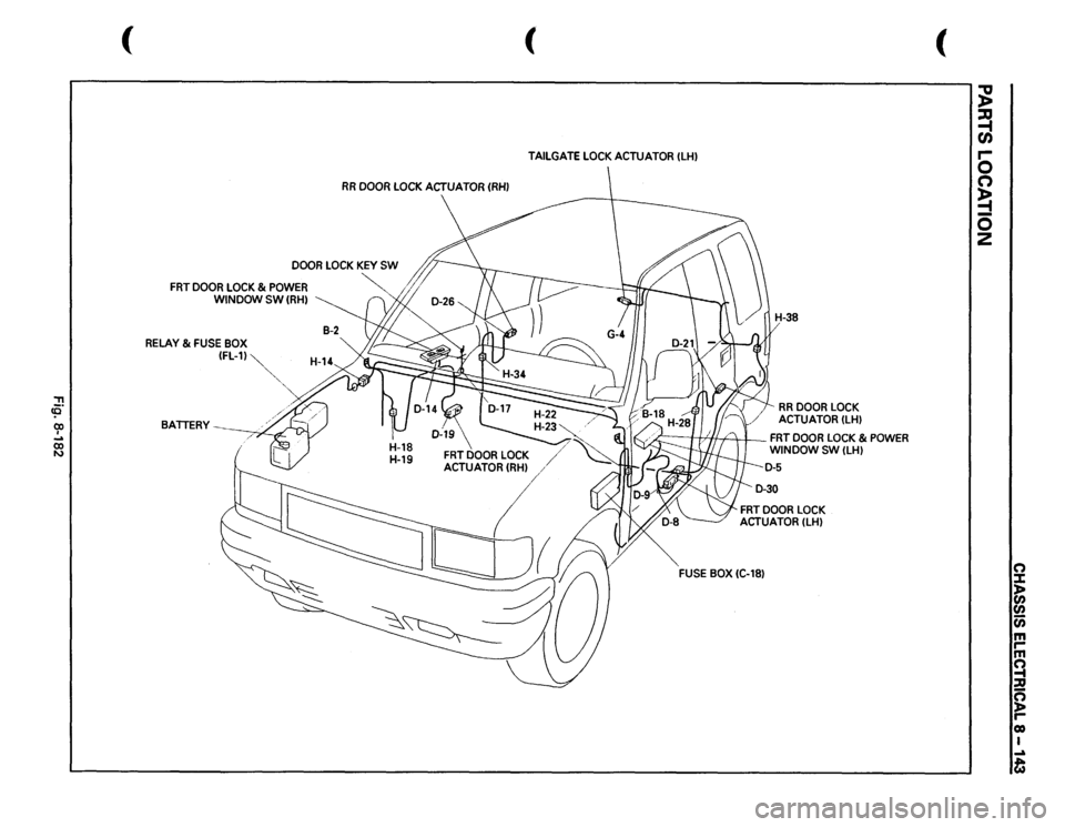
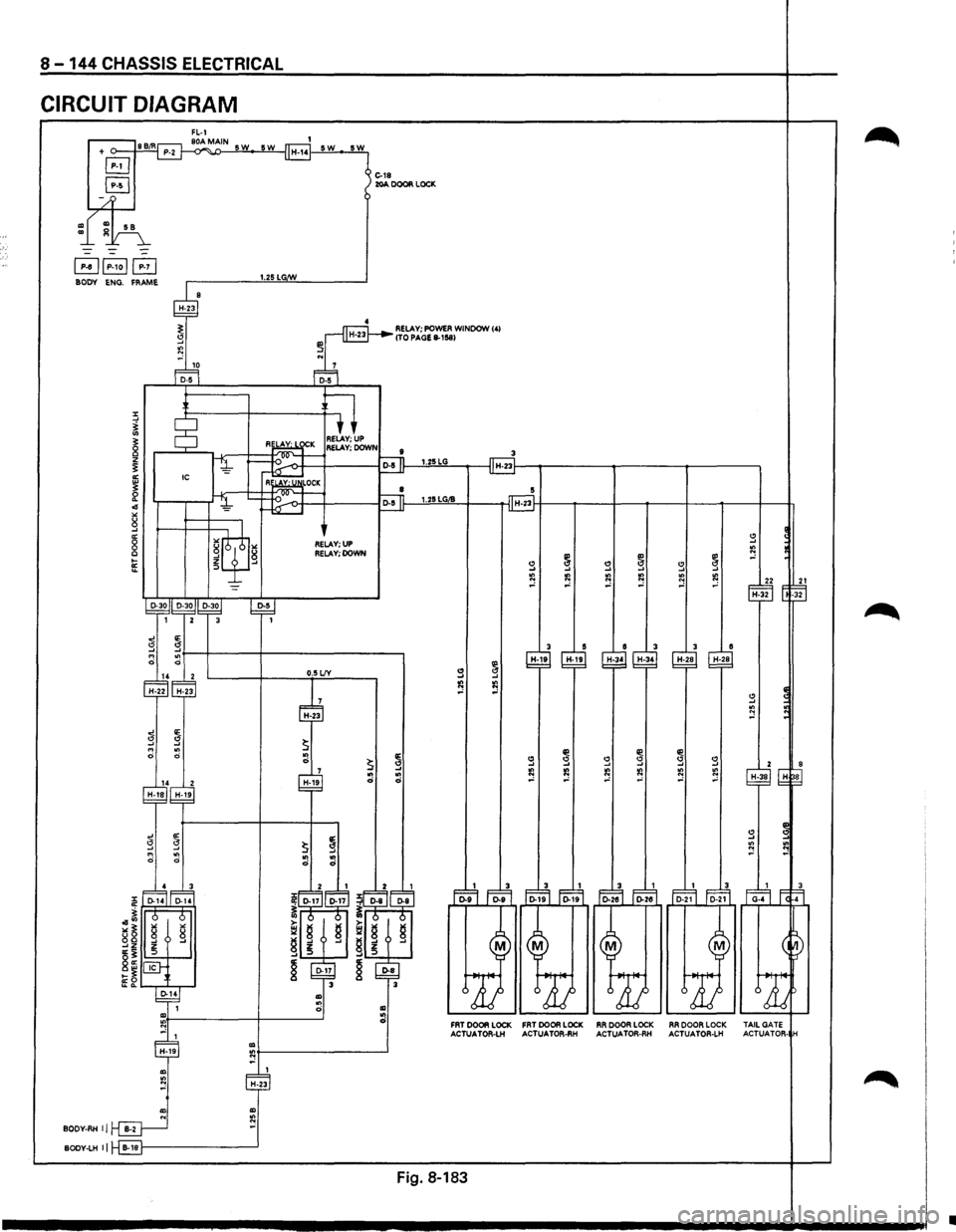
POWER DOOR LOCK
GENERAL DESCRIPTION
The circuit consists of the door lock (& power window) switch, door lock actuator for the front and rea door,
tailgate
lock actuator and the door lock key switch.
The
front door lock switch-LH is always provided with battery voltage. The key or the inside lock bu on on
the both driver's and the
front passenger's door can activate the lock mechanism of all the doors (in< luding
the tailgate).
When the driver's
door lock switch or the front passenger's door lock switch is turned on, current fie ws for
about one second to the door lock actuator of each door connected in parallel with the front door ock (&
power window) switch-LH to activate the actuator to lock and unlock the doors.
OPERATION OF DOOR LOCK BY DRIVER SIDE LOCK KEY SWITCH
LOCK
UNLOCK
BATTERY(+) POWER WINDOW RELAY
.....-1::::::;---'li) ~
fi ::> ~ = } TO ACTUATOR IC IE~CC (ACTUATOR OPERATES
I l lj~:.-.>+T++==-TO LOCK SIDE)
W=~~~~'l g
Jlf!
FRONT DOOR LOCK (& POWER WINDOW l SW-LH
sb2-f---+---w
U ~rh;±,i DOOR LOCK ~LfJg KEY SW-LH
u =
BATTERY(+) POWER WINDOW RELAY
,..,~T =
I IEl.
CS ~:t-o·++ 1+==-TO UNLOCK SIDE)
IL...t=:t=~~w.~ g
~q;J
FRONT DOOR LOCK (& POWER WINDOW) SW-LH
[b =
U ~8 DOOR LOCK
~l.f} KEY SW-LH
NOTE: Arrow marks"=" indicate the direction of current.
Fig. 8-181
IIIII
Page 1333 of 1928
"T1 !0 (X) I ... (X) N
(
RR
DOOR
LOCK
ACTUATOR
(RHI
DOOR
LOCK
KEY
SW
"-
FRT
DOOR
LOCK
& POWER
WINDOW SW
(RHI
RELAY
& FUSE
BOX (FL-11~
BATTERY
' ,,
( TAILGATE
LOCK
ACTUATOR
(LHI
RR
DOOR
LOCK
ACTUATOR
(LHI
h.=
I //If/:
I
FRT
DOOR
LOCK
& POWER
WINDOW
SW
(LHI
FRT
DOOR
LOCK
ACTUATOR
(LHI
FUSE
BOX
(C-181
(
~ ~ r-0 n ~ 0
2
(") J: )> en
en (i) m rm ~ :a g reo I ...a t
Page 1334 of 1928
8 -144 CHASSIS ELECTRICAL
CIRCUIT DIAGRAM
FL-1 86/R 80AMAIN SW 5W + o---+=-=-4 P-2 ~
GJ
GJ
/
1 H-14 SW
~~P-1ol~ BODY ENG. FRAME 1.25 LG/W
5W
1 C-18 J 20A DOOR LOCK
4 RELAY; POWER WINDOW 141 ITO PAGE 8-1!58)
...
r---D~D~~~1o~------------~~5~7-----,
§*f-----+------+--.51
RE' AY· I I'V'K RELAY; UP 1__;;=.l...v----J--·m~;:;:::::I--·~RELAY; DOWN I ~ ~ ~ 1.25LG IC H-23f----.----------------t--------~
R~LOCK 8 5 ~--r-_)~~i_~t~~~~l~~o~t~--~----~ID-si~~~1-~25~LG~~~~--H~~--~----+---~---4----~--~--~
~!
-
RELAY; UP RELAY; DOWN
D-30JI D-30/1 D-30j ~ 1 2
0 14 2 H-22 H-23
14 2
H-18 H-19
"' BODY-RHij~
3 1
0.5 L!Y
H-19
"' tQ~------------~
"' H-23
"' "' N "' BODY-LH II B-181---------------_J
22 21 H-32 0 -32
3 5 e 3 3 e H-19 H-19
H-34 H-34 H-28 H-28
" .... IQ ~ -' s "' ~ ::!
~ ~ II! s s g s 2
~ IQ
IQ ~ ~ "' IQ H-38 ~ N -' -' -' -'
s ~
"' ;, N ::! "'
Fo.~ Fo-~ Fo-i'f1 Fo-~ ~~ Fo-~ Fo-~ ~2~ Faf1 f. r.1
M M
FAT DOOR LOCK FAT DOOR LOCK ACTUATOA-LH ACTUA TOR-AH
Fig. 8-183
M
ARDOORLOCK ACTUATOR-RH
M
RADOOALOCK ACTUATOA-LH TAILGATE
ACTUATOR· H
•
Page 1336 of 1928
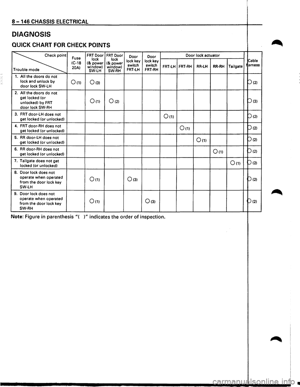
8 -146 CHASSIS ELECTRICAL
DIAGNOSIS
QUICK CHART FOR CHECK POINTS ~
~
Fuse FRT Door FRT Door
Door Door Door
lock actuator
lock lock
lock key lock key
Cable IC-18 I& power I& power 20AI window)
window) switch switch FRT-LH FRT-RH RR-LH RR-RH Tailgate
arness
T SW-LH SW-RH FRT-LH FRT-RH
1. All the doors do not
lock and unlock by
door lock SW-LH 0(1) 0131
P121
2. All the doors do not
get locked (or
0(1) 0121 Pl31 unlocked) by FRT door lock SW-RH
3. FRT door-LH does not 0(1) P121 get locked {or unlocked)
4. FRT door-RH does not 0111 P121 get
locked (or unlocked)
5. RR door-LH does not 0(1) P121 get locked (or unlocked)
6. RR door-RH does not 0111 P121 get
locked (or unlocked)
7. Tailgate does
not get 0111 P121 locked (or unlocked)
8. Door lock does not
operate when operated 0111 0131 p(2) from the door lock key SW-LH
9. Door lock does not ~ operate when operated Om 0131 P121 from the door lock key SW-RH
Note: Figure in parenthesis "( )" indicates the order of inspection.
~
•